
Abstract:To develop modal macro-strain (MMS) identification techniques and improve their applicability in a continuous health monitoring system for civil infrastructures, the concept of operational macro-strain shape (OMSS) and the corresponding identification method are proposed under unknown ever-changing loading conditions, and the MMS is then obtained. The core of the proposed technique is mainly based on the specific property that the macro-strain transmissibility tends to be independent of external excitations at the poles of the system and converges to a unique value. The proposed method is verified using the experimental data from a three-span continuous beam excited by an impact hammer at different locations. The identified results are also compared with the commonly used methods, such as the peak-picking (PP) method, the stochastic subspace identification (SSI) method, and numerical results, in the case of unknown input forces. Results show that the proposed technique has unique merits in accuracy and robustness due to its combining multiple tests under changing loading conditions, which also reveal the promising application of the distributed strain sensing system in identifying MMS of operational structures, as well as in the structural health monitoring (SHM) field.
Key words:macro-stain/distributed strain; fiber Bragg grating (FBG); operational modal analysis (OMA); operational deflection shape (ODS); transmissibility
In recent decades, many research endeavors have focused on the use of modal parameters involving frequency, mode shape, and modal strain energy to detect damage in civil infrastructures. These modal-related damage detection methods were proved to be effective and reasonable[1-4]. Therefore, the acquisition of reliable and robust modal parameters is the first and foremost concern to be settled. In terms of modal analysis, one of the major drawbacks when using frequency response function (FRF) in the frequency-domain methods is the necessity of knowing the external excitations being applied to the structures, which is impossible for large scaled structures, such as bridges or buildings in operation. Therefore, some time-domain methods, such as stochastic subspace identification (SSI) and peak-picking (PP) methods which do not need the specific knowledge of applied forces in many cases, are more appropriate for operational mode identification[5]. However, different loading conditions may lead to unacceptable errors in results between different tests. Furthermore, a different choice in fitted model ranks may result in various outcomes in the SSI method, which needs to be determined by combining the finite element model (FEM), and the PP technique seems incapable of pinpointing high-order modes within the noisy environment. Thus, results based on these methods usually cannot meet expectations.
Ambient excitations applied to structures always vary in locations and magnitudes under different operational conditions, e.g., moving vehicles, wind loads applied to a bridge. Due to the lack of input information, mode shapes cannot be normalized by mass matrices. Hence, it is reasonable to expect that mode shapes will undergo noticeable changes under different operational conditions[6]. Consequently, it may not be helpful to make use of mode-based methods for structural health monitoring (SHM).
Developments over the years on the distributed strain measurement techniques are considered to be effective for data acquisition measures, which can easily capture both the global and local information of the structure[7-9]. Hence, this technique and the corresponding macro-strain modal identification strategies have been developed rapidly[7-12]. This paper aims to extend the previous research concerning the macro-strain modal identification and its application, which will enlarge our knowledge in SHM for employing distributed optical fiber sensing techniques. The specific property that the macro-strain transmissibility tends to be independent from the excitation force at the poles of the system and converges to a unique value will act as the basis of the proposed technique. Numerical analysis and experimental verification are also provided in this paper.
1.1 Establishment of operational macro-strain shape
The macro-strain frequency response function (SFRF) can be expressed as[9]

(1)
where ![]() denotes the macro-strain response measured by the h-th sensor with the force p applied at the coordinate k; Φmr, Φlr are the r-th mode shape values of the m and l nodes, respectively; L is the strain transformation matrix linking displacements to macro-strains; Mr, Kr and Cr are the generalized modal mass, stiffness, and damping, respectively; Ω={ω1, ω2, …, ωr} is the resonance frequency matrix. G is the load effect matrix. Let
denotes the macro-strain response measured by the h-th sensor with the force p applied at the coordinate k; Φmr, Φlr are the r-th mode shape values of the m and l nodes, respectively; L is the strain transformation matrix linking displacements to macro-strains; Mr, Kr and Cr are the generalized modal mass, stiffness, and damping, respectively; Ω={ω1, ω2, …, ωr} is the resonance frequency matrix. G is the load effect matrix. Let ![]() LhmΦmr be the r-th macro-strain mode value in a length of gauge, and then, the SFRF can be written in a partial fraction form as
LhmΦmr be the r-th macro-strain mode value in a length of gauge, and then, the SFRF can be written in a partial fraction form as

(2)
where J denotes the number of modes. From poles λr, ![]() and residuals LhmΦmr,
and residuals LhmΦmr, ![]() , the resonance frequencies and macro-strain mode shapes corresponding to various orders of macro-strain modes can be obtained by using the singular value decomposition (SVD) algorithm[13], respectively. The macro-strain mode shapes can be also obtained by linking peak values at the same frequency of the SFRFs.
, the resonance frequencies and macro-strain mode shapes corresponding to various orders of macro-strain modes can be obtained by using the singular value decomposition (SVD) algorithm[13], respectively. The macro-strain mode shapes can be also obtained by linking peak values at the same frequency of the SFRFs.
For a long-gauge measured element in a linear structure with stationary stochastic processes from the auto and cross spectral densities, the following two equations are given:

(3)


(4)
Here, we define ![]() (Ω) as the macro-strain transmissibility between coordinates i and j when force p is applied on coordinate k. The operational deflection shape (ODS) is the deflection shape of a structure subjected to a single frequency harmonic excitation[14]. Similarly, the concept of the operational macro-strain shape (OMSS) herein is proposed to obtain a good knowledge of the authentic macro-strain state for the structure at the given frequency. Usually, the OMSS can be obtained from SVD or linked values of SFRFs at the arbitrary selected frequency, and from which modal macro-stain shapes can be obtained at the poles of the system (resonance frequencies) corresponding to predominant peaks. Unfortunately, the OMSS cannot be directly extracted from SFRFs due to an unknown input force. However, inspired by Ref.[15], the macro-strain transmissibilities can be used instead to express the OMSS, which can be described with transmissibilities of macro-strain responses by choosing a fixed reference sensor i, and consequently the objective can be achieved.
(Ω) as the macro-strain transmissibility between coordinates i and j when force p is applied on coordinate k. The operational deflection shape (ODS) is the deflection shape of a structure subjected to a single frequency harmonic excitation[14]. Similarly, the concept of the operational macro-strain shape (OMSS) herein is proposed to obtain a good knowledge of the authentic macro-strain state for the structure at the given frequency. Usually, the OMSS can be obtained from SVD or linked values of SFRFs at the arbitrary selected frequency, and from which modal macro-stain shapes can be obtained at the poles of the system (resonance frequencies) corresponding to predominant peaks. Unfortunately, the OMSS cannot be directly extracted from SFRFs due to an unknown input force. However, inspired by Ref.[15], the macro-strain transmissibilities can be used instead to express the OMSS, which can be described with transmissibilities of macro-strain responses by choosing a fixed reference sensor i, and consequently the objective can be achieved.
OMSS(ωr)=[![]() ,
,

(5)
The referred sensor i can be set arbitrarily except for the modal node with zero value. The subscript k denotes the k-th test. However, it should be noted that frequencies corresponding to predominant peaks can only be regarded as pseudo resonance frequencies since they are the spurious poles of the system, which are quite different from those obtained from SFRFs; thus, OMSSs at these extrusive frequencies cannot be deemed as MMS. Only if the OMSS is at the authentic pole of the system, can it be interpreted as MMS. Hence, the issue of the MMS identification is adjusted to find the poles of the system.
1.2 MMS identification from OMSS
In the previous section, the OMSS is defined as the macro-strain state of an operational structure at a given frequency and the modal macro-strain shape can be obtained by the OMSS at the poles of the system (resonance frequencies). The resonance frequencies in general are obtained from the values corresponding to the predominant peaks in SFRFs. However, note the fact that transmissibilities can vary with the location of input forces[16]. As a result, the correct poles from strain transmissibility response function (STRFs) are still need to be determined due to the inconsistence between STRFs and SFRFs. There is an identification algorithm by using macro-strain transimissibilities, which will facilitate obtaining the poles of the system.
Considering Eq.(2) and taking the limit value of Eq.(4) yields


(6)
Here, we have

(7)

(8)
Substituting Eqs.(7) and (8) into Eq.(6), the following expression can be obtained:

(9)
Similarly, Eq.(10) can be also obtained when the force p is applied at coordinate g.

(10)
When the limit value of the transmissibility function for s approaches to the system’s pole λr, it converges to Φir/Φjr, which implies that macro-strain transmissibility functions in this case are excluded from the role of the force location of k or g.
It is not difficult to observe that the limit values of the subtraction between the two transmissibility functions with respect to different input locations satisfies the following equation:

(11)
Eq.(11) means that there are several intersection points to be revealed in the same figure by using different transmissibilities in different loading cases, which can be realized by using the proposed method of combining multiple test data. To illustrate the determination of the identified results, the reciprocal value of the subtraction in different transmissibilities, named as RDT, is defined. This contributes more to illustrate the results since it shows the dominant peaks in the same manner of the power density spectrum.

(12)
To clarify the proposed MMS identification technique using only output data under the changing loading conditions, a flow chart is given as shown in Fig.1.
2.1 Specimen details
The experiments were carried out on a three-span continuous simple supported steel beam (1.1 m+1.4 m+1.1 m, 3.6 m in total) in the following physical characteristics: Young’s modulus of 200 GN/m2; the mass density of 7 850 kg/m3; the dimensions of 3.400 m×0.500 m×0.008 m (see Fig.2). Four elaborate piers with hinges are installed to support the beam. Small gaps between the bolt and bolt hole are reserved to release motion in a longitudinal direction. Degrees of freedom in transverse and vertical directions are restricted, as well as the rotation around transverse direction.

Fig.1 Flow chart of proposed MMS identification technique

Fig.2 The experimental specimen and data acquisition system
2.2 Measurement Scheme
A set of commercial fiber Bragg grating (FBG) strain sensors are attached at the bottom of the girder to show their high precision performance in the test. The gauge of each sensor is set to be 0.2 m. Hence, there are 17 sensors in total, as illustrated in Fig.3. The demodulating system (Sm130, Micron Optics, Inc.) is used for the macro-strain data acquisition at a sampling rate of 100 Hz.

Fig.3 Scheme of FBG sensors placement attached at the bottom of the girder (unit:m)
2.3 Experimental procedures
Impact testing is generally a common way to excite a structure with equal energy distribution within a band of interest, which will result in a multi-mode excitation. In this experiment, the impact force is first applied at the position of 0.4 m (the second sensor) by using an impact hammer, and then the repetition is performed at the location of 1.4 m (the seventh sensor) along the beam. Two sets of time-history macro-strain data are collected and stored in the database, and then they are transferred to a Matlab (Version 2012b) environment for advanced processing.
Figs.4(a) and (b) reveal the waterfalls of the SFRFs and STRFs in all FBG sensors, respectively. Four peaks in each SFRF can be observed, as well as three peaks in each STRF. Clearly, the frequencies at the peaks in SFRFs are the various orders of the MMS. However, the frequencies corresponding to the prominent peaks can only be regarded as pseudo poles in STRFs. Moreover, the maximum and minimum values of STRFs do not coincide with those of SFRFs.

(a)

(b)
Fig.4 Comparison of SFRFs and STRFs from all FBG sensors.(a) Waterfall of normalized SFRFs; (b) Waterfall of normalized STRFs
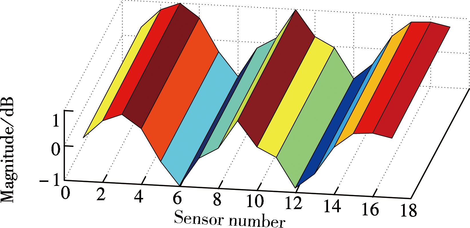
By picking and jointing the peaks of the STRF of each FBG sensor in waterfall figures, the OMSSs are obtained as presented in the first section. Figs.5(a), (b), (c) and (d) illustrate the un-normalized MMSs corresponding to the first four order modes, respectively. Figs.5(e), (f) and (g) show some un-normalized OMSSs at selected outlier frequencies; however, they do not represent any order of the MMS. These OMSSs comprise not only the structural information but also excitations. Therefore, thepoles of the system (resonance frequencies) should be determined by Eqs.(4) to (12) first to eliminate the influence of the input force and then to obtain MMSs.

(a)

(b)
(c)

(d)

(e)

(f)

(g)
Fig.5 Comparisons of MMS and OMSS at outlier frequencies.(a) The 1st MMS at 12.16 Hz; (b) The 2nd MMS at 21.20 Hz; (c) The 3rd MMS at 24.88 Hz; (d) The 4th MMS at 46.12 Hz; (e) The 1st OMSS at 13.42 Hz; (f) The 2nd OMSS at 23.45 Hz; (g) The 3rd OMSS at 41.32 Hz
To verify the accuracy of the proposed method, a three-dimensional finite element model (FEM) of the experimental specimen is established (see Fig.6) and will further be used to perform the modal analysis by the FE software of ANSYS (Version 12.0). The result will act as the baseline for comparison.

Fig.6 FEM corresponding to experimental specimen
The resonance frequencies identified from the proposed RDT procedure are compared with those from the widely used SSI and PP methods as well as numerical results as shown in Tab.1 and Fig.7. It can be seen that the resonance frequencies identified by the proposed technique agree well with other independent methods. However, the proposed method is of much higher accuracy, while the PP method has low capacity to recognize higher modes and the stabilized dots for the SSI method appear at non-resonance frequencies.
Tab.1 Comparisons of identified resonance frequencies from different methods Hz

ModefrequencyFEmethodPPmethodSSImethodRDTmethodThe1stmode12.1611.7211.6512.30The2ndmode21.0721.0921.6120.95The3rdmode24.9524.0824.90The4thmode45.9645.8645.95

Fig.7 Comparisons of identified resonance frequencies from different methods
Fig.8 shows the comparisons of the maximum-value-normalized MMS between experimental identified results from the proposed technique and numerical results from the FE method at the first four resonance frequencies. It can be easily seen that these two results differ little in bothmagnitude and phase, particularly for the first two MMSs, which is promising for our goals.

(a)

(b)

(c)

(d)
Fig.8 Numerical and experimental comparisons at the first four resonance frequencies for MMSs.(a) The 1st order; (b) The 2nd order; (c) The 3rd order; (d) The 4th order
The concept of OMSS and the associated MMS identification technique are proposed to estimate modal macro-strain parameters including resonance frequencies and macro-strain mode shapes of a structure. It is more close to the reality for employing OMSS at the poles of the system to express MMS for operational structures. Compared with the previous MMS identification methods under changing ambient excitations, the proposed method has several unique merits: First, it is applicable for huge structures of which the external excitations are unknown; secondly, it is capable of pinpointing high-order macro-strain modes compared with the PP method; and it has good robust results due to the reason that it allows for the combination of multiple tests.
The proposed method is independent with the input forces applied to structures at the poles of the system. The unknown operational forces can be arbitrary, such as colored noise, swept sine, impact, etc., as long as they are persistently exciting within the frequency bands of interest, which implies a potential capacity for use in real operational structures.
References:
[1]Shi Z Y, Law S S, Zhang L M. Improved damage quantification from elemental modal strain energy change [J]. Journal of Mechanical Engineering, 2008, 128(5): 521-529. DOI:10.1061/(asce)0733-9399(2002)128:5(521). (in Chinese)
[2]Yan W J, Huang T L, Ren W X. Damage detection method based on element modal strain energy sensitivity advances in structural engineering [J]. Advances in Structural Engineering, 2010, 13(6): 1075-1088. DOI:10.1260/1369-4332.13.6.1075.
[3]Seyedpoor S M. A two stage method for structural damage detection using a modal strain energy based index and particle swarm optimization [J]. International Journal of Non-Linear Mechanics, 2012, 47(1): 1-8. DOI:10.1016/j.ijnonlinmec.2011.07.011.
[4]Xu Z D, Wu K Y. Damage detection for space truss structures based on strain mode under ambient excitation [J]. Journal of Engineering Mechanics, ASCE, 2012, 138(10): 1215-1223. DOI:10.1061/(asce)em.1943-7889.0000426.
[5]Zong Z H, Ruan Y, Ren W X. Experimental modal analysis of a large-span cable stayed concrete bridge with single tower under ambient excitation [J]. Journal of Vibration Engineering, 2004, 17(5): 684-687. (in Chinese)
[6]Parloo E, Verboven P, Guillaume P, et al. Sensitivity-based operational mode shape normalization [J]. Mechanical Systems and Signal Processing, 2002, 16(5): 757-767. DOI:10.1006/mssp.2002.1498.
[7]Zhang J, Guo S L, Wu Z S, et al. Structural identification and damage detection through long-gauge strain measurements [J]. Engineering Structures, 2015, 99(15): 173-183. DOI:10.1016/j.engstruct.2015.04.024.
[8]Adewuyi A P, Wu Z S, Serker N H M K. Assessment of vibration-based damage identification methods using displacement and distributed strain measurements [J]. Structural Health Monitoring, 2009, 8(6): 443-461. DOI:10.1177/1475921709340964.
[9]Xu Z D, Zeng X, Li S. Damage detection strategy using strain-mode residual trends for long-span bridges [J]. Journal of Computing in Civil Engineering, 2015, 29(5): 04014064-1-04014064-11. DOI:10.1061/(asce)cp.1943-5487.0000371.
[10]Hong W, Wu Z S, Yang C Q, et al. Investigation on the damage identification of bridges using distributed long-gauge dynamic macro-strain response under ambient excitation [J]. Journal of Intelligent Material Systems and Structures, 2012, 23(1): 85-103. DOI:10.1177/1045389x11430743.
[11]Wan C F,Hong W, Wu Z S, et al. Testing and monitoring for a large scale truss bridge using long-gauge fiber optic sensors [J]. Key Engineering Materials, 2013, 569: 223-229. DOI:10.4028/www.scientific.net/kem.569-570.223.
[12]Wan C F,Liu J X, Hong W, et al. Bridge assessment and health monitoring with distributed long-gauge FBG sensors [J]. International Journal of Distributed Sensor Networks, 2013, 2013(6): 494260-1-494260-10. DOI:10.1155/2013/494260.
[13]Yao Z Y, Wang F Q, Liu Y. Stochastic subspace identification method based on continuous model for modal parameters of engineering structures [J]. Journal of Southeast University (Natural Science Edition), 2004, 34(3): 382-385. (in Chinese)
[14]Brincker R, Kirkegaard P H. Special issue on operational modal analysis[J]. Mechanical Systems and Signal Processing, 2010, 24(5):1209-1212. DOI:10.1016/j.ymssp.2010.03.005.
[15]Vold H, Schwarz B, Richardson M H, et al. Measuring operating deflection shapes under non-stationary conditions [C]//Proceedings of SPIE—The International Society for Optical Engineering. San Antonio, USA, 2000: 239-244.
[16]Devriendt C, Guillaume P. Identification of modal parameters from transmissibility measurements [J]. Journal of Sound and Vibration, 2008, 314(1/2):343-356. DOI:10.1016/j.jsv.2007.12.0227.
摘要:为了发展宏应变模态识别技术并提高其在土木结构健康监测中的适用能力,提出了运行宏应变形状的概念及相应的获取方法,并进一步识别了宏应变模态,以适用结构处于不断变化的未知激励环境.所提新技术的核心是基于宏应变传递率函数在系统极值点独立于激励源并收敛的独特性质.通过对一个三跨连续梁结构模型进行力锤激励,对所提方法进行了试验验证,同时将识别结果与未知激励条件下最常用的峰值拾取法(PP)和随机子空间法(SSI)以及数值结果进行了对比分析.结果表明,该方法联合了多次测试数据,在不同加载工况下,其识别结果在精度和稳定性方面具有独特优势,同时也表明分布式应变传感系统在运行结构宏应变模态识别及结构健康监测领域应用前景好.
关键词:宏应变/分布式应变;光纤布拉格光栅;运行模态分析;工作变形分析;传递率
中图分类号:TP317
Received:2015-10-19.
Biographies:Li Shu (1984—), male, graduate; Xu Zhaodong (corresponding author), male, doctor, professor, zhdxu@163.com.
Foundation item:s:The National Natural Science Foudation of China (No.51578140), the Natural Science Foundation of Jiangsu Province (No.BK20151092), Scientific Innovation Research of College Graduates in Jiangsu Province (No.CXZZ12_0108).
Citation:Li Shu, Xu Zhaodong, Wang Shaojie, et al. Modal macro-strain identification from operational macro-strain shape under changing loading conditions[J].Journal of Southeast University (English Edition),2016,32(2):219-225.doi:10.3969/j.issn.1003-7985.2016.02.015.
doi:10.3969/j.issn.1003-7985.2016.02.015