Design of a novel modular self-reconfigurable robotcapable of self-turning
Design of a novel modular self-reconfigurable robotcapable of self-turning
Qiao Guifang Song Guangming Zhang Ying Sun Huiyu Wei Zhong
(School of Instrument Science and Engineering, Southeast University, Nanjing 210096, China)
Abstract:To solve the problem of inaccurate angle adjustment in the self-assembly process, a new homogenous hybrid modular self-reconfigurable robot—Xmobot is designed. Each module has four rotary joints and a self-turning mechanism. With the proposed self-turning mechanism, the angle adjusting accuracy of the module is increased to 2°, and the relative position adjusting efficiency of the module in the self-assembly process is also improved. The measured maximum moving distance of the proposed module in a gait cycle is 11.0 cm. Aiming at the multiple degree of freedom (MDOF) feature of the proposed module, a motion controller based on the central pattern generator (CPG) is proposed. The control of five joints of the module only requires two CPG oscillators. The CPG-based motion controller has three basic output modes, i.e. the oscillation, the rotation, and the fixed modes. The serpentine and the wheeled movements of the H-shaped robot are simulated, respectively. The results show that the average velocities of the two movements are 15.2 and 20.1 m/min, respectively. The proposed CPG-based motion controller is evaluated to be effective.
Mobile robots with specific capabilities and fixed morphology are applied in well-defined environments for the given tasks. The applications of the wheeled and tracked mobile robots have achieved notable success. However, uncertain environments and various tasks require robotic systems capable of flexible locomotion. However, the more versatile the mobile robots, the more they cost.
In 1980s, Fukuda et al.[1] proposed a modular self-reconfigurable robotic system named CEBOT, which can reconfigure itself to adapt to various tasks and uncertain environments. In general, the modular self-reconfigurable robot (MSR) is a robotic system which contains a collection of simple modules. It can change its configuration by rearranging the connectivity of each module, in order to adapt to new circumstances, perform new tasks, or recover from damage. Compared with the conventional mobile robots, the MSRs have advantages such as self-adaptability, self-repair, scalability, and low-cost[2]. In this paper, a five-DOF homogeneous hybrid MSR with a self-turning mechanism is designed. For the MDOF module, a novel CPG-based controller which can generate multiple output modes is also proposed.
1 Related Work
Remarkable progress has been made in the MSR module design, reconstruction planning, and docking methods during the last three decades. Some typical MSRs are shown in Tab.1. Based on the geometric arrangement of modules, the MSRs are divided into three categories, i.e. chain, lattice, and hybrid types. The robots can also be classified by the structure of the modules[3], i.e. homogeneous and heterogeneous systems. PolyBot[4] and CONRO[5] are chain systems. The movement of the chain systems is performed by the locomotion of the assembled robot. M-Cube[7] is a lattice system which has six rotational faceplates for connecting. The movement of lattice systems is implemented by reconstruction planning. Hybrid systems combine both the advantages of the chain and the lattice systems, i.e. MTRAN[9], SuperBot[10], and Roombot[11].
Self-assembly is one of the remarkable capabilities of the MSRs. In the self-assembly process, the active modules adjust the position and angle deviations with respect to the passive modules. In order to promote the efficiency of the self-assembly, the mobility of the modules must be enhanced. Three assembled chain modules[14-15] can perform rectilinear, lateral shift and turning motion. The four-DOF ModRED[6] can perform rectilinear and turning motion. Based on the structure of MTRAN, SuperBot[10] added a rotary joint to make the module more flexible. iMobot[13] added two chip-shaped wheels at the two ends of the module. The angle adjustment is the most significant step in the self-assembly process. The chain systems can adjust the angle deviation by bending the middle joint[15]. SuperBot[6], iMobot[10], and ModRED[13] can perform the turning motion by spinning the rotary joint. However, the accuracy of the angle adjustment is low. Sambot[8] and SMORES[12] with differential wheels can easily perform the angle deviation adjustment.
Owing to the characteristics of MSRs, the motion controller of the MSRs should be adaptive. The controllers are subdivided into high-level and low-level controllers. The high-level controller includes the hormone-based controller[5], the ESL controller[8], the role-based controller[16], and the constraint-based controller[17]. However, the joint motors of the MSRs are directly controlled by the low-level controller, i.e. gait table[4], harmonic oscillator based controller[14], and phase automata[18]. Gait table and phase automata are easy to implement. However, the gait transition of the robots is abrupt. Both controllers are off-line preplanned and lack sensory feedback. Therefore, the MSRs cannot adapt to complex environments. The harmonic oscillator-based controller has less control parameters and can be integrated with simple sensory feedback. However, the gait transition is also abrupt. The central pattern generator (CPG) is a neural network, which describes how the vertebrate motor control system works[19]. The CPG-based controller has fewer control parameters, and it can be integrated with various sensory feedback. The topology of the CPG network can be changed with the reconstruction of the MSRs. The CPG-based controllers have already been applied for controlling the MSRs[8-9,20].
2 Mechanical Design
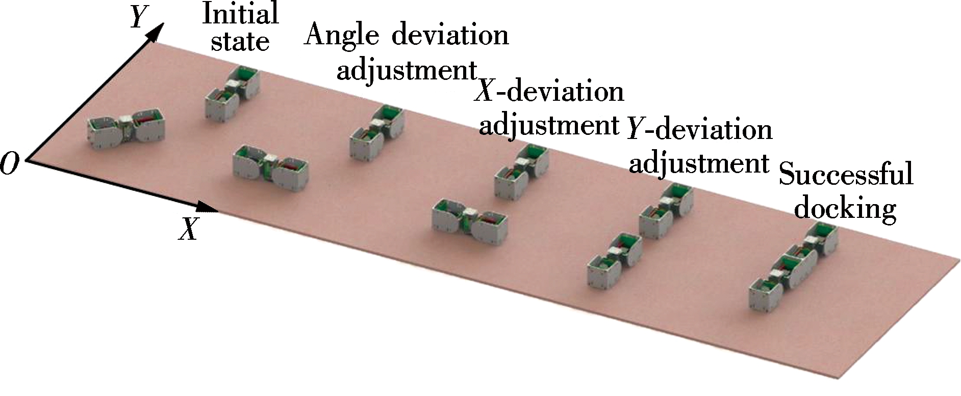
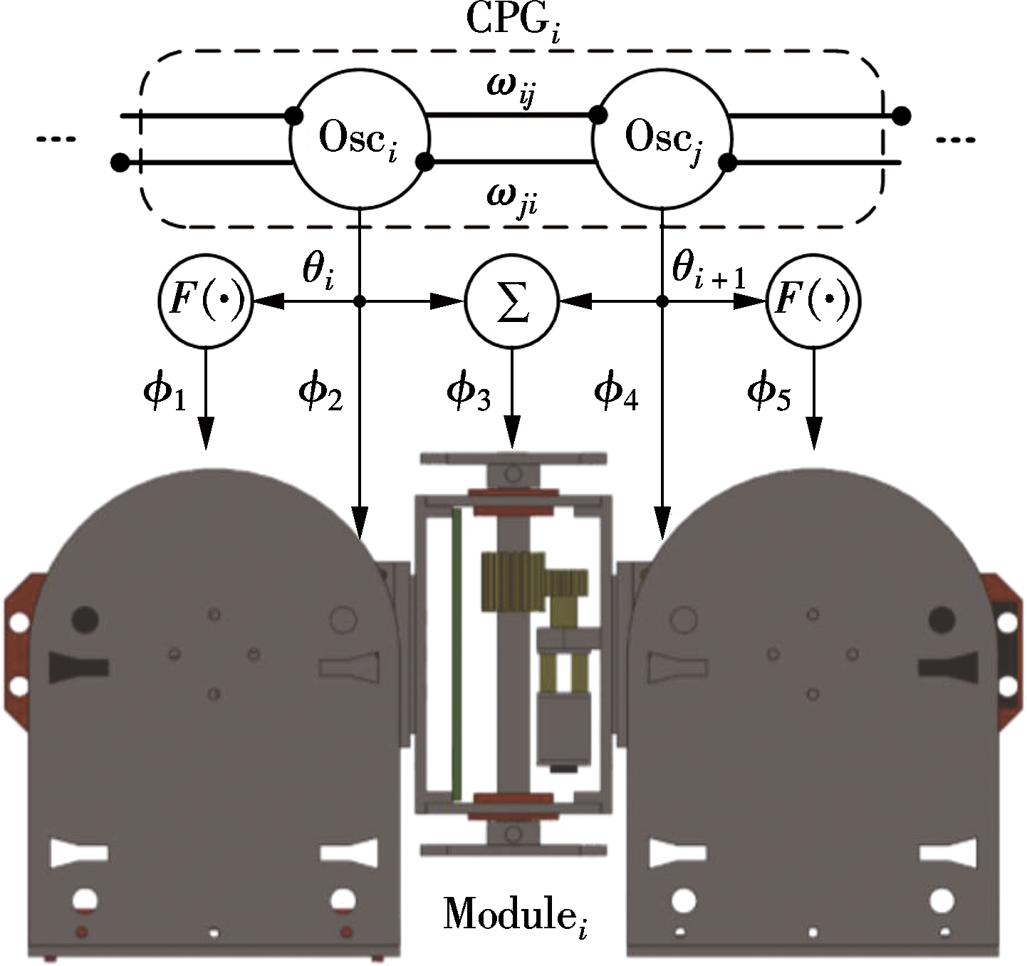
Xmobot, which belongs to the homogenous and hybrid type, is shown in Fig.1(a). Fig.1(b) shows the prototype of the Xmobot module. The module has a symmetrical mechanical structure. The dimension of the module is 70 mm×70 mm×227 mm. The module consists of a front part, a middle part, and a rear part. Two pitch joints and three rotary joints make the module flexible. The middle part is a self-turning mechanism which is designed to adjust the direction precisely. As shown in Fig.1(c), the module has two modes when the self-turning mechanism is in different states. The module can switch the modes by synchronously rotating the first and third rotary joints. The two pitch joints rotate downward to raise the middle part. In order to avoid being obstructed by the ground, the rotating angle of the two pitch joints must be greater than 7.2°. The self-turning mechanism is composed of a cuboid frame and two supporting disks. When the module is in mode B, the center of gravity of the module focuses on the bottom support disk. The front and the rear parts of the module are lifted off the ground. The module can perform precise turning motion through the proposed self-turning mechanism. The detailed self-assembly procedure of two modules is presented in Fig.2. The static module is called the passive module. The moving module called the active module adjusts its position and angle deviation to dock with the passive module. The X-axis deviation, Y-axis deviation, and angle deviation are adjusted in turn.
Fig.1 The proposed Xmobot module with five independent DOFs. (a) CAD model; (b) The prototype; (c) The switching procedures of mode A and mode B
Fig.2 The self-assembly process of two Xmobot modules
3 Kinematic Analysis
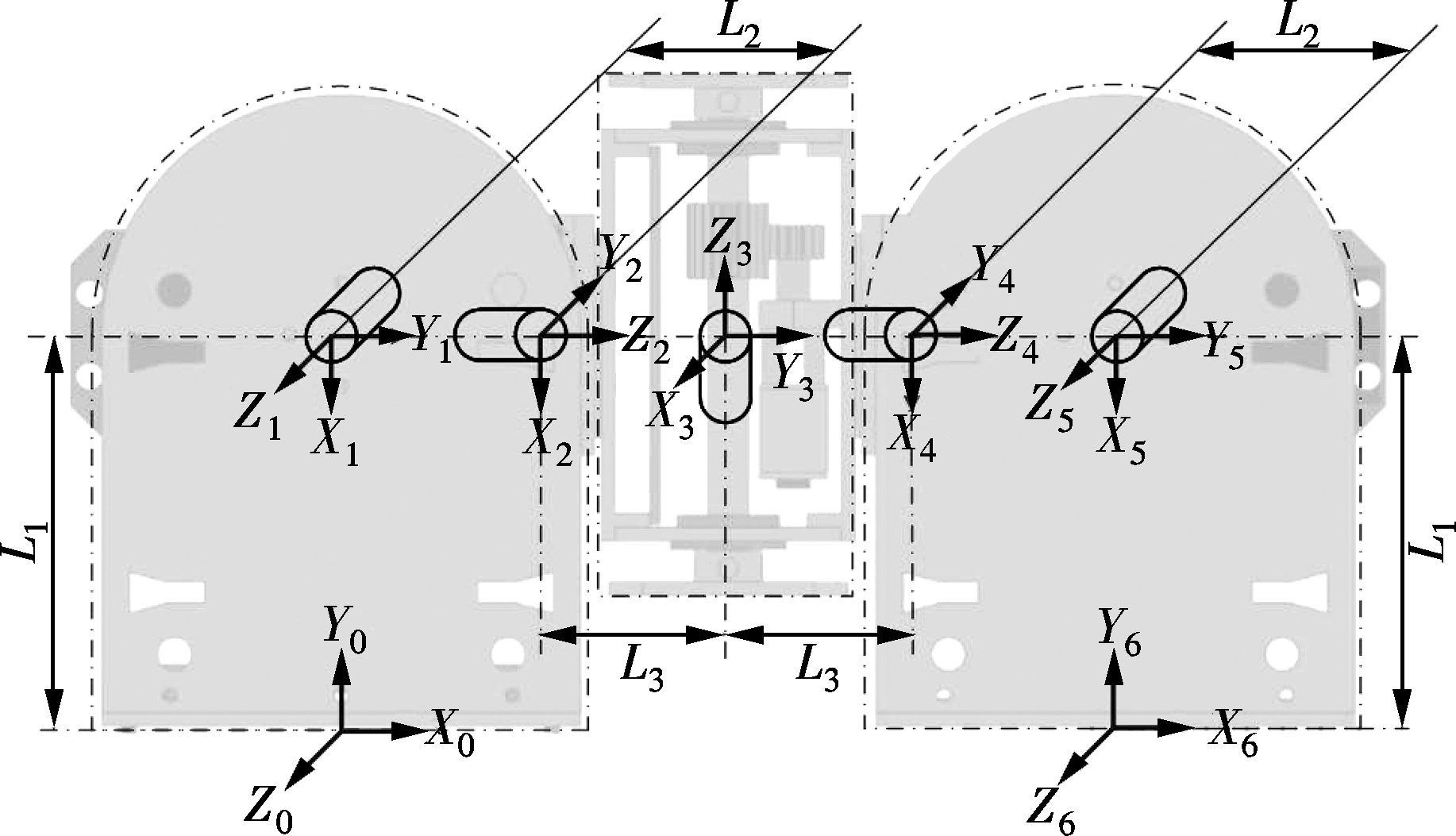
In order to analyze the workspace of the proposed Xmobot module, the kinematic schematic of the single module is illustrated in Fig.3, where the corresponding coordinates are attached to each joint and the two endpoints. The mechanical dimensions are indicated in the figure. The joint variables are represented by θi. Based on the kinematic schematic in Fig.3, the transformation matrices i+1Ti for each joint are calculated as
(1)
(2)
(3)
(4)
(5)
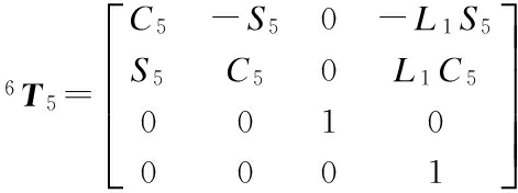
6T0=1T02T14T25T46T5
(6)
where cosθi and sinθi are abbreviated to Ci and Si, respectively.
Fig.3 The kinematic schematic of the single module
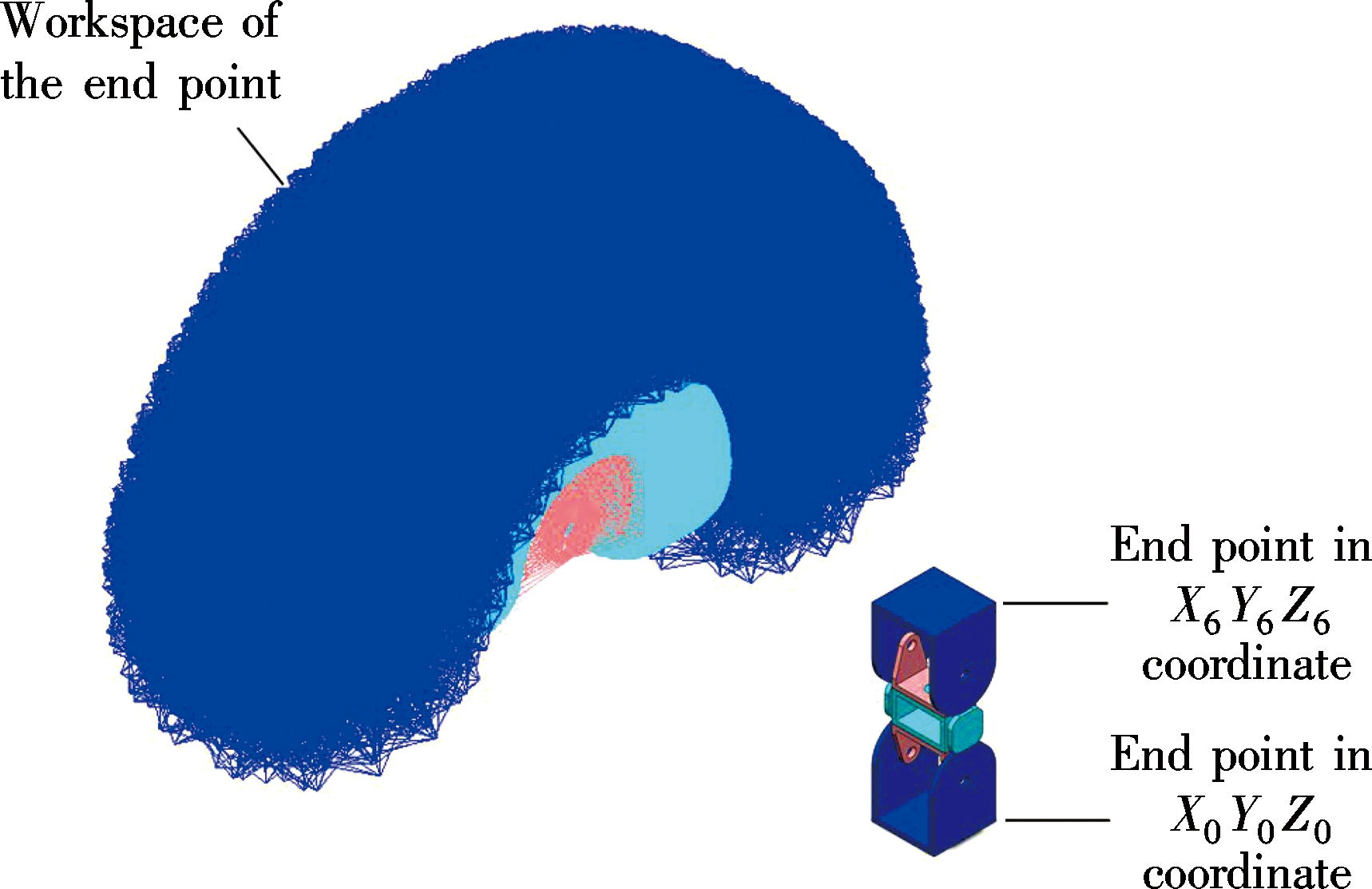
One endpoint of the module in X0Y0Z0 coordinate is fixed on the ground. The workspace of the Xmobot module is shown in Fig.4.
4 Central Pattern Generator for Modules
A CPG-based controller proposed for Roombot has three output modes, i.e. the oscillation, the rotation, and the fixed modes[21]. However, the controller is so complex that each joint is controlled by an oscillator. In this case, the proposed Xmobot module with five DOFs
Fig.4 The workspace of the single module simulated in the MSC.Adams
must be controlled by five mutually coupled oscillators. The equations of each oscillator are expressed as
(7)
where ri, xi, and θi are the state variables which stand for the amplitude, the offset, and the phase, respectively; ωij and φij are the coupling weight and phase bias between the i-th and the j-th oscillators, respectively; ai and bi are the positive constants which determine the rise times of the amplitude and the offset to the desired values Ri and Xi; Ri, Xi, and wi are the intrinsic control parameters for the desired amplitude, offset, and frequency of the oscillators.
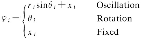
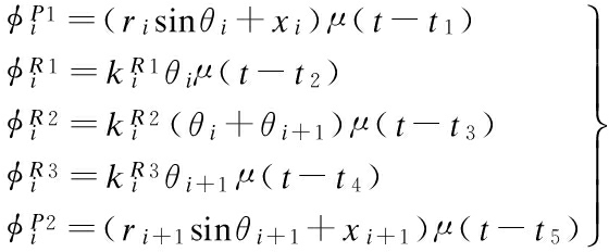
The two pitch joints of the Xmobot module perform an oscillatory motion. The three rotary joints perform a rotatory motion. To maintain the posture of the assembled robots, the certain joints should be fixed at the target position. Therefore, the control signal must be derived with different functions corresponding to the desired movements. The output φi of the CPG-based controller is given by
(8)
The output function is used to control the oscillation, the rotation, and the fixed motion. The output exhibits limit cycle behavior in the oscillation mode. For the rotation mode, a constant-speed profile is generated. The third mode allows the controller to lock a joint at the fixed position. The frequency of each oscillator is typically set to be equal. The rotation joint is controlled by the output θi of each oscillator which largely depends on the frequency wi. Therefore, the oscillation and the rotation modes can be controlled by the same oscillator. The scale and the complexity of the CPG network are reduced. The CPG-based controller proposed in this paper merely uses two oscillators to control the module with five joints. The schematics of the CPG-based controller for the single module are presented in Fig.5. Two oscillators mutually coupled are applied to produce the basic synchronous signal. The first pitch joint and the first rotary joint of the single module are controlled by the i-th oscillator. The second pitch joint and the third rotary joint are controlled by the (i+1)-th oscillator. The second rotary joint is controlled by the sum of the two oscillators. The output functions are given as
(9)
where the step function u(t-ti) is used to determine when the control signal is applied to the corresponding joint. The parameter is used to control the angular velocity ratio of the rotary joints.
Fig.5 The schematics of the CPG-based controller proposed for the Xmobot module
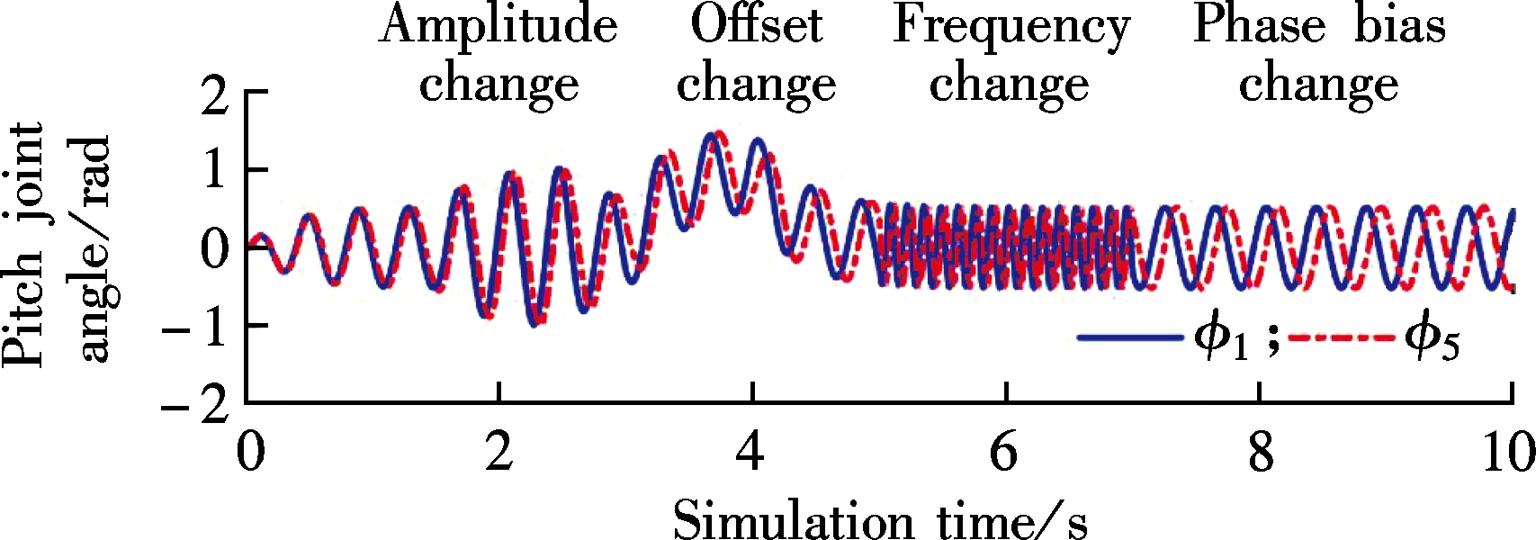
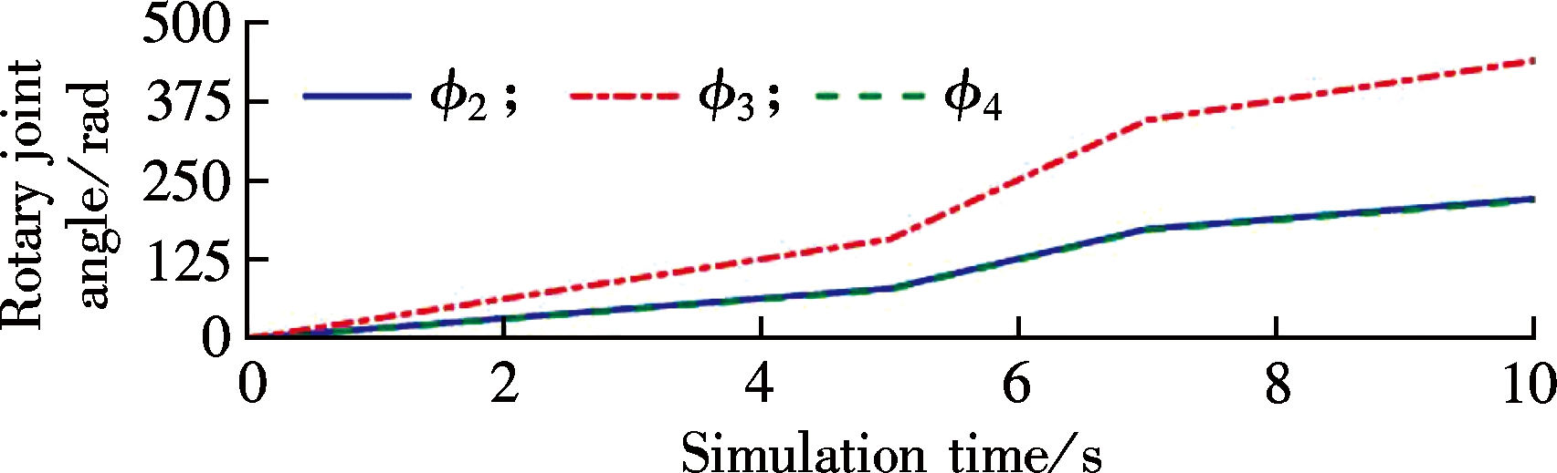
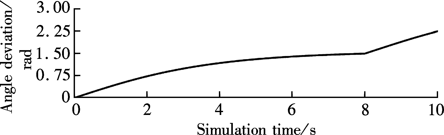
The proposed CPG-based controller is analyzed through the Simulink. The impacts of the amplitude, the offset, the phase bias, and the frequency on the output of the CPG-based controller are calculated. The results are presented in Fig.6. The angle deviation of the two oscillators converges to a stable value which is determined by the phase bias φij. The period of the oscillators is determined by the frequency wi. The amplitude and the offset determine the oscillation range and the equilibrium position.
5 Locomotion Experiments and Simulation
5.1 Motion of single module
The Xmobot module in both modes can perform two types of inchworm-like movements. The mobility of the single module in both modes A and B has been evaluated. The results demonstrate that the maximum moving distance of the module in mode A is 11.0 cm. The maximum moving distance of the module in mode B is 8.8 cm. As shown in Fig.7, the module in both modes performs two different gaits.
(a)
(b)
(c)Fig.6 Synchronization behavior of two coupled oscillators for the single Xmobot module. (a) Two pitch joints in the oscillatory mode; (b) Three rotary joints in rotational mode; (c) The angle deviation of the two oscillators
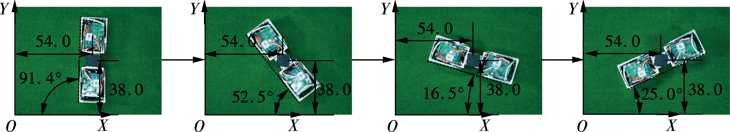
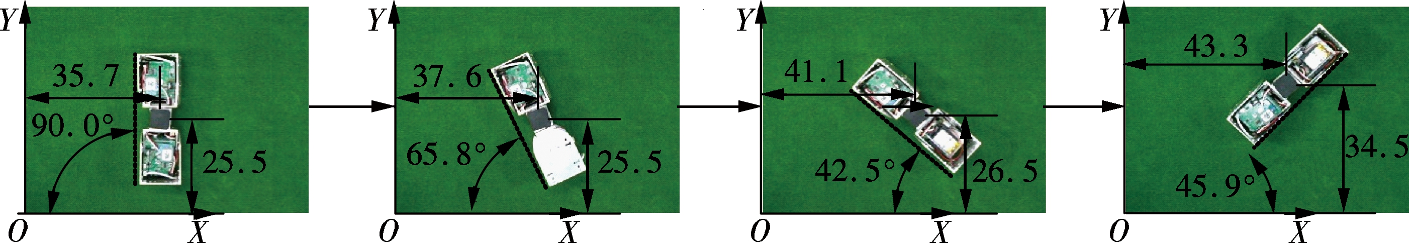
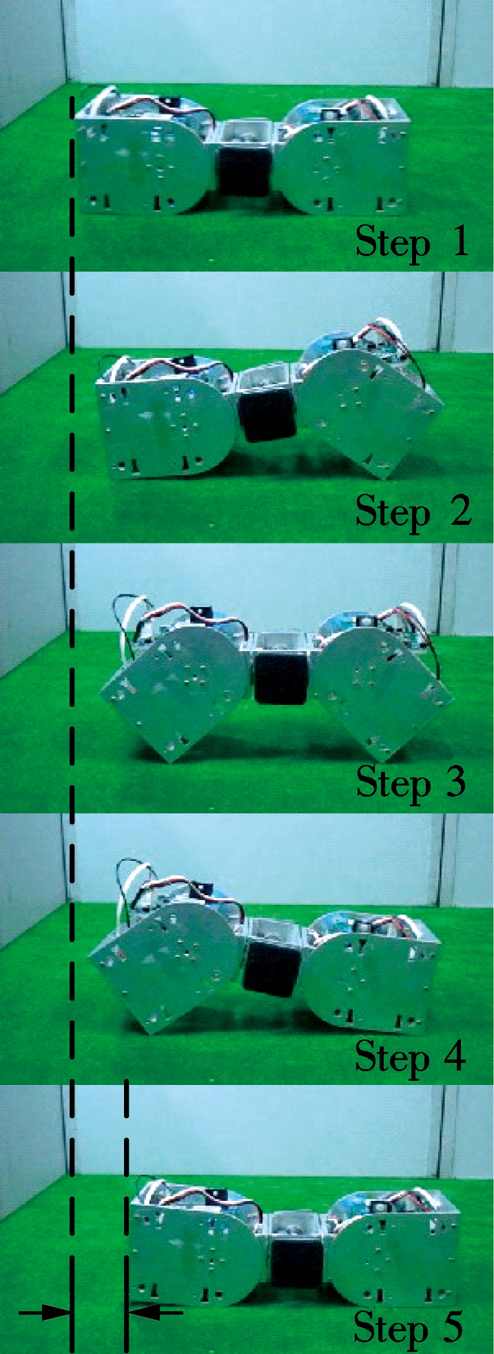
The performance of the proposed self-turning mechanism was tested. The module can perform two types of turning motion. The first one is the same as the SuperBot[10] which rotates the first or the third rotary joints independently. The experimental result of the turning motion performed by the module in mode B is shown in Fig.8. The average angle per rotation step in the experiments is 22.5°. The accuracy of this motion is affected by the mechanical dimensions and the friction. In addition, the rotation center of the module is not fixed. This will result in the changes of the previous calculation of the horizontal and the vertical deviations. Overall, this type of turning motion has drawbacks of unfixed rotatory center and low adjusting accuracy. As shown in Fig.9, the module performs the turning motion by the self-turning mechanism. It can be seen that the module in mode B turns at a fixed center. Due to the mechanical error of the gears, the accuracy of the angular adjustment is nearly 2°. The Transmote[15] performs the turning motion by bending its joints. However, the accuracy of the turning motion performed by Transmote is heavily influenced by the friction. The adjustment accuracy of the Transmote module is 3.1°. Therefore, the proposed self-turning mechanism for Xmobot module is evaluated to be effective.
5.2 Locomotion simulation of H-shaped robot
The performances of the proposed CPG-based controller were evaluated through the co-simulation of Matlab/Simulink and MSC.Adams. The topology of the CPG network and the H-shaped configuration assembled by 9 modules are shown in Fig.10. The H-shaped robot can perform the flexible locomotion of quadruped, snake, and wheeled vehicle. When the H-shape robot performs the snake-like locomotion, the joints of the ninth module are fixed at the initial position, and the other joints perform sinusoidal motion. Therefore, the outputs of the 17th and the 18th oscillators are set as 0. The output modes of the other oscillators are oscillation. Both the left and the right sides perform the same serpentine locomotion which is presented in Ref.[22]. The parameters of the oscillators are determined by
(a) (b) (c) (d)
Fig.7 Rectilinear motion experiments in which the module performs the two gaits in different modes. (a) Gait 1 in mode A; (b) Gait 2 in mode A; (c) Gait 1 in mode B; (d) Gait 2 in mode B
Fig.8 The turning motion of the module in mode B when the module rotates its first rotary joints (unit: mm)
Fig.9 The turning motion of the module in mode B with the proposed self-turning mechanism (unit: mm)
(10)
where α is the winding angle of the serpenoid curve; Kn is the number of periods in the serpenoid curve; N is the number of the joints; L is the total length of the snake-like robot.
Matlab/SimulinkMSC. Adams/A ViewFig.10 The simulation of the H-shaped robot assembled by the Xmobot module performed by the Matlab/Simulink and MSC.Adams
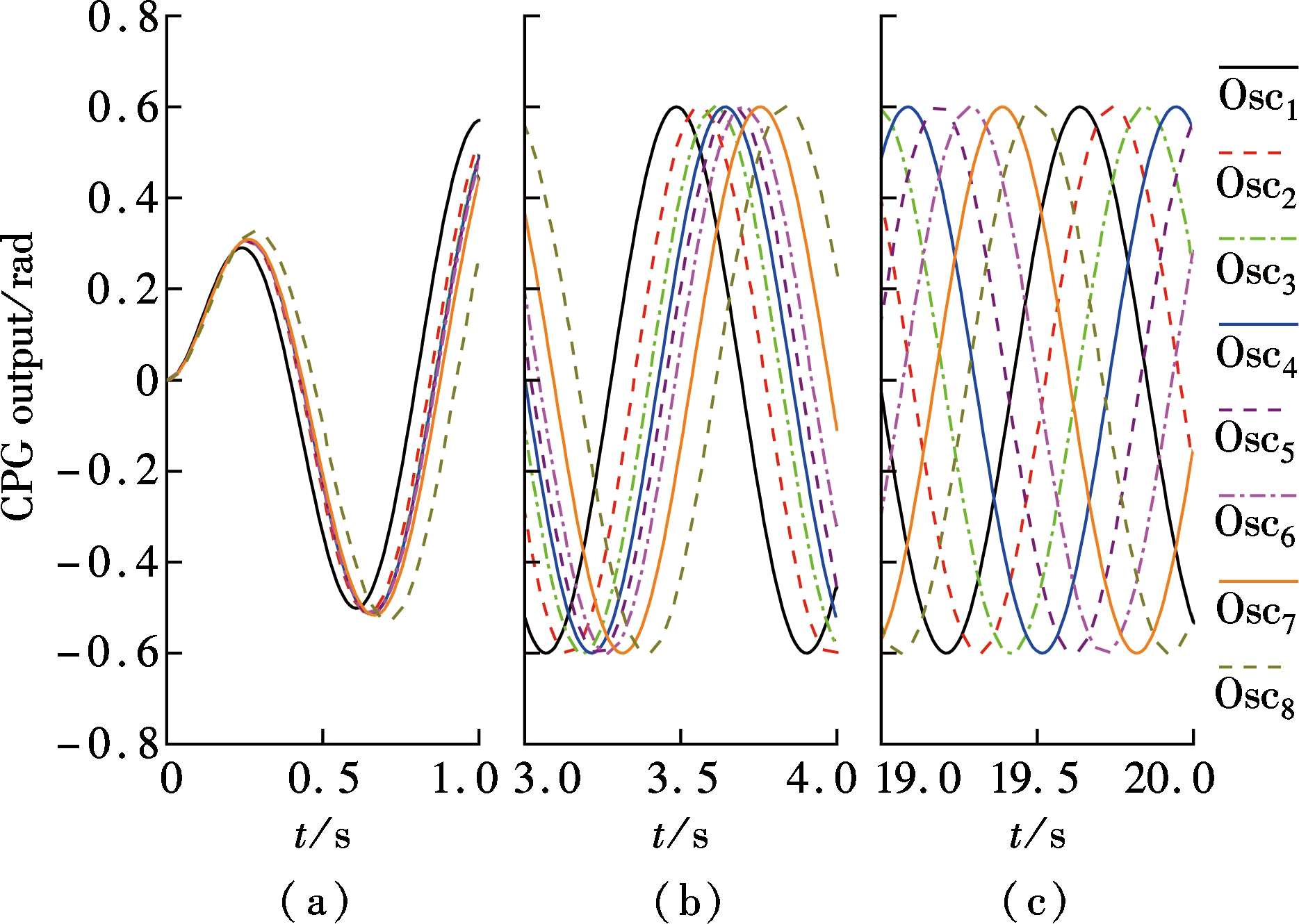
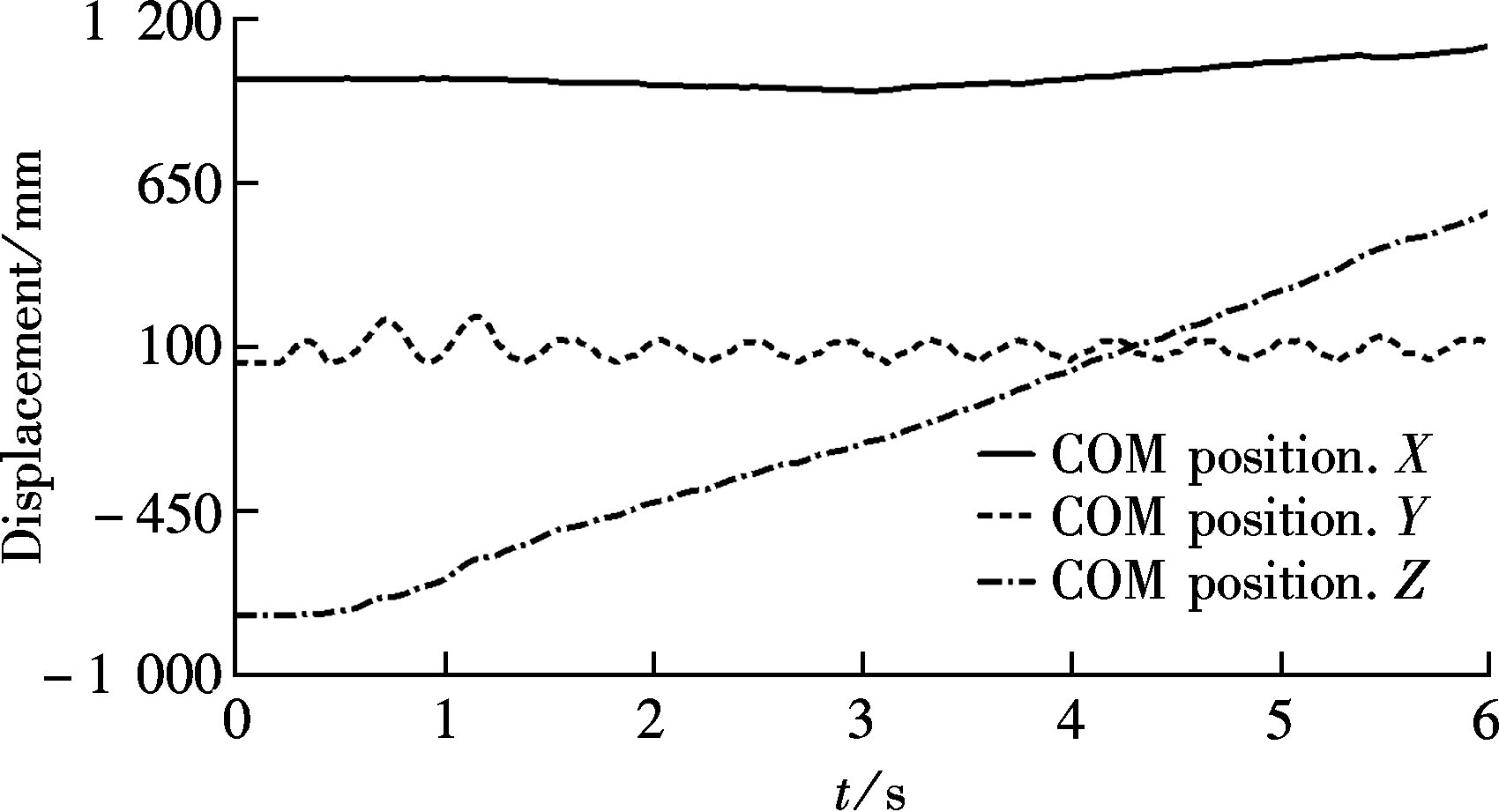
After determining the parameters, the outputs of each oscillator are presented in Fig.11. The oscillators start from the initial state, and synchronize gradually. The simulation animation of the snake-like locomotion in MSC.Adams is shown in Fig.12. The H-shaped robot performs a snake-like locomotion. The simulation results are presented in Fig.13. The H-shaped robot moves along the Z-axis. The average velocity of the H-shaped robot is about 15.2 m/min. Owing to the influence of the friction, the H-shaped robot has direction deviation.
Fig.11 The outputs of each oscillator when the H-shaped robot performs snake-like locomotion. (a) 0 s≤t≤1 s; (b) 3 s≤t≤4 s; (c) 19 s≤t≤20 s
Fig.13 The simulation results of the COM position when the H-shaped robot performs the snake-like locomotion
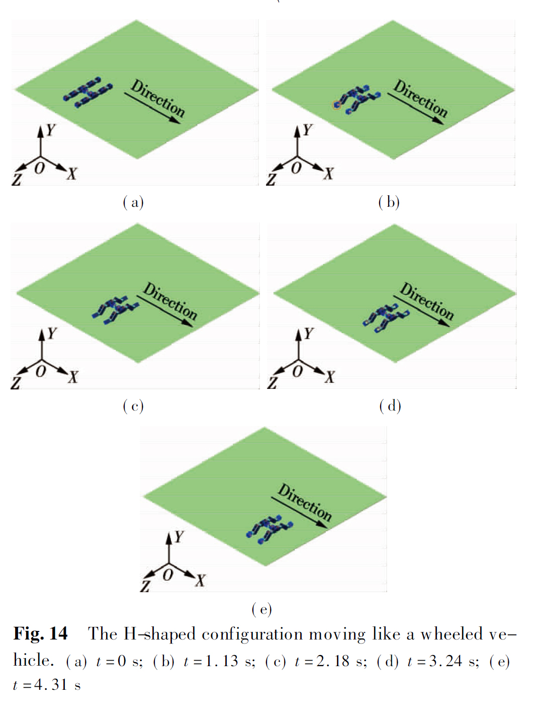
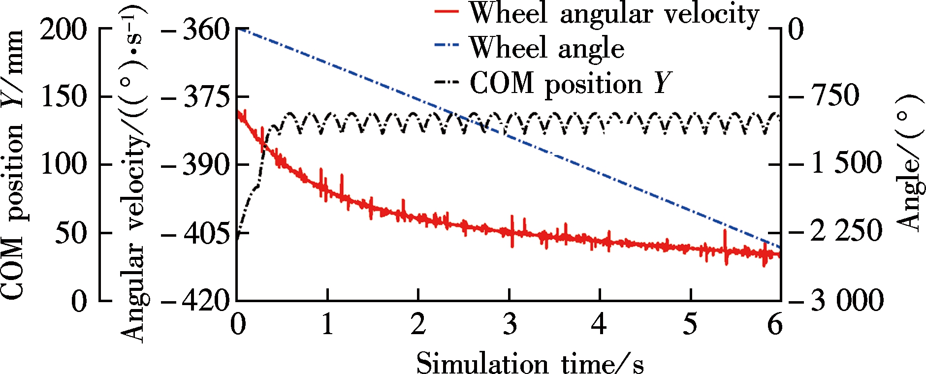
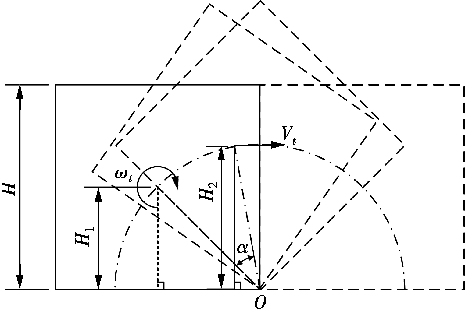
Besides, the H-shaped robot can also perform a wheeled motion. As shown in Fig.14, the four end joints of the H-shaped robot act as wheels. The moving direction of the robot is along the X-axis. The positions of the second, the seventh, the tenth, and the fifteenth oscillators are fixed at -π/4, and the positions of the third, the sixth, the eleventh, and the fourteenth oscillators are fixed at π/4. The others are fixed at the initial position except for the first, the eighth, the ninth, and the sixteenth oscillators which are used to control the wheels. The simulation results are presented in Fig.15. Due to the square shape of the Xmobot modules, the vertical position of COM oscillates periodically. As shown in Fig.16, the front or rear part is rotated around the point O. The vertical position of the COM is calculated by
(11)
Fig.15 The simulation results of the wheeled motion performed by the H-shaped robot
Fig.16 The geometry analysis of the wheel-driven movement
The relationship between the angular velocity and the velocity are calculated by
(12)
The average velocity of the H-shaped robot in the wheeled mode is about 20.1 m/min. The parameters of the CPG controller were set to be equal when the H-shaped robot performed the snake-like and the wheeled motions. The mobility efficiency of the wheeled mode is higher than that of the snake-like mode. In conclusion, the proposed CPG-based controller can be easily implemented in the designed Xmobot.
6 Conclusion
A flexible modular self-reconfigurable robot—Xmobot is designed, implemented, and simulated. A novel self-turning mechanism is designed to solve the inaccuracy problem of the angle adjustment in the self-assembly process. Owing to the different positions of the self-turning mechanism, the module has two modes. In each mode, the module can perform two types of turning and rectilinear movements. The maximum distance that the module moves per gait cycle is 11.0 cm. The angle adjusting accuracy is increased to 2°. A CPG-based controller is proposed to control the motion of Xmobot. Only two oscillators are utilized to control the module with five joints. The CPG-based controller has three output modes, i.e. oscillation, rotation, and fixed modes. In the simulation, the proposed CPG-based controller was applied to control the locomotion of the H-shaped robot. The simulation results show that Xmobot can perform flexible locomotion through the proposed CPG-based controller. The velocities of the H-shaped robot in the two motions are 15.4 and 20.1 m/min, respectively.
References:
[1]Fukuda T, Nakagawa S, Kawauchi Y, et al. Self-organizing robots based on cell structures—CEBOT[C]//IEEEInternationalWorkshoponIntelligentRobots. Tokyo, Japan, 1988: 145-150.
[2]Yim M, Shen W, Salemi B, et al. Modular self-reconfigurable robotsystems: Challenges and opportunities for the future[J]. IEEERobotAutomationMagazine, 2007, 14(1): 43-52.
[4]Yim M, Zhang Y, Roufas K, et al. Connecting and disconnecting for chain self-reconfiguration with PolyBot[J]. IEEE/ASMETransactionsonMechatronics, 2003, 7(4): 442-451.
[5]Shen W M, Salemi B, Will P. Hormone-inspired adaptive communication and distributed control for CONRO self-reconfigurable robots[J]. IEEETransactionsonRobotics & Automation, 2002, 18(52): 700-712.
[6]Hossain S G M, Nelson C A, Chu K D, et al. Kinematics and interfacing of ModRED: A self-healing capable, 4DOF modular self-reconfigurable robot[J]. JournalofMechanisms & Robotics, 2014, 6(4): 1491-1503.
[7]Fei Y Q, Zhu Y L, Xia P. Analysis on self-morphing process of self-reconfigurable modular robot[J]. InternationalJournalofAdvancedRoboticSystems, 2009, 6(3): 215-222. DOI: 10.5772/7232.
[8]Wei H, Li H, Chen Y, et al. A general framework integrating exploration, self-assembly and locomotion control for swarm robots[C]//ProceedingsofIEEEInternationalConferenceonRoboticsandBiomimetics. Phuket, Thailand, 2011: 871-876.
[9]Kamimura A, Kurokawa H, Yoshida E, et al. Automatic locomotion design and experiments for a modular robotic system[J]. IEEE/ASMETransactionsonMechatronics, 2005, 10(3): 314-325.
[10]Salemi B, Moll M, Shen W. SUPERBOT: A deployable, multi-functional, and modular self-reconfigurable robotic system [C]//ProceedingsofIEEE/RSJInternationalConferenceonIntelligentRobotsandSystems. Beijing, China, 2006: 3636-3641.
[11]Spröwitz A, Moeckel R, Vespignani M, et al. Roombots: A hardware perspective on 3D self-reconfiguration and locomotion with a homogeneous modular robot [J]. RoboticsandAutonomousSystems, 2014, 62(7): 1016-1033. DOI: 10.1016/j.robot.2013.08.011.
[12]Davey J, Kwok N, Yim M. Emulating self-reconfigurable robots-design of the SMORES system[C]//ProceedingsofIEEE/RSJInternationalConferenceonIntelligentRobotsandSystems. Vilamoura, Algarve, Portugal, 2012: 4464-4469.
[13]Ryland G G, Cheng H H. Design of iMobot, an intelligent reconfigurable mobile robot with novel locomotion[C]//ProceedingsofIEEEInternationalConferenceonRobotsandAutomation. Anchorage, AK, USA, 2010: 60-65.
[14]Gomez J, Zhang H, Boemo E. Locomotion principles of 1D topology pitch and pitch-yaw-connecting modular robots [M]//Bioinspirationandroboticswalkingandclimbingrobots. Rijeka, Croatia: INTECH Open Access Publisher, 2007: 403-428.
[15]Qiao G F, Song G M, Wang W G, et al. Design and implementation of a modular self-reconfigurable robot [J]. InternationalJournalofAdvancedRoboticSystems, 2014, 11(47): 1-12.
[16]Stoy K, Shen W M, Will P M. Using role-based control to produce locomotion in chain-type self-reconfigurable robots [J]. IEEETransactionsonMechatronics, 2002, 7(4): 410-417.
[17]Zhang Y, Fromherz M P J, Crawford L S, et al. A general constraint-based control framework with examples in modular self-reconfigurable robots[C]//ProceedingsofIEEE/RSJInternationalConferenceonIntelligentRobotsandSystems. Lausanne, Switzerland, 2002, 3: 2163-2168.
[18]Zhang Y, Yim M, Eldershaw C, et al. Phase automata: A programming model of locomotion gaits for scalable chain-type modular robots [C]//ProceedingsofIEEE/RSJInternationalConferenceonIntelligentRobotsandSystems. Las Vegas, NV, USA, 2003, 3: 2442-2447.
[19]Ijspeert A J. Central pattern generators for locomotion control in animals and robots: A review [J]. NeuralNetworks, 2008, 21(4): 642-653. DOI: 10.1016/j.neunet.2008.03.014.
[20]Marbach D, Ijspeert A J. Online optimization of modular robot locomotion [C]//ProceedingsofIEEEInternationalConferenceonMechatronicsandAutomation. Niagara Falls, Canada, 2005: 248-253.
[21]Pouya S, van den Kieboom J, Spröwitz A, et al. Automatic gait generation in modular robots: “To oscillate or to rotate, that is the question” [C]//ProceedingsofIEEE/RSJInternationalConferenceonIntelligentRobotsandSystems. Taipei, China, 2010: 514-520.
[22]Hirose S. Biologicallyinspiredrobots: Snake-likelocomotorsandmanipulators [M]. Oxford, UK: Oxford University Press, 1993.
Citation:Qiao Guifang, Song Guangming, Zhang Ying, et al. Design of a novel modular self-reconfigurable robot capable of self-turning[J].Journal of Southeast University (English Edition),2016,32(3):293-300.DOI:10.3969/j.issn.1003-7985.2016.03.006.
Foundation item:s:The National Natural Science Foundation of China (No.61375076), Research & Innovation Program for Graduate Student in Universities of Jiangsu Province (No.CXLX13-085), the Scientific Research Foundation of Graduate School of Southeast University (No.YBJJ1350).
Biographies:Qiao Guifang (1987—), male, doctor; Song Guangming (corresponding author), male, doctor, professor, mikesong@seu.edu.cn.


 (a)
(a) 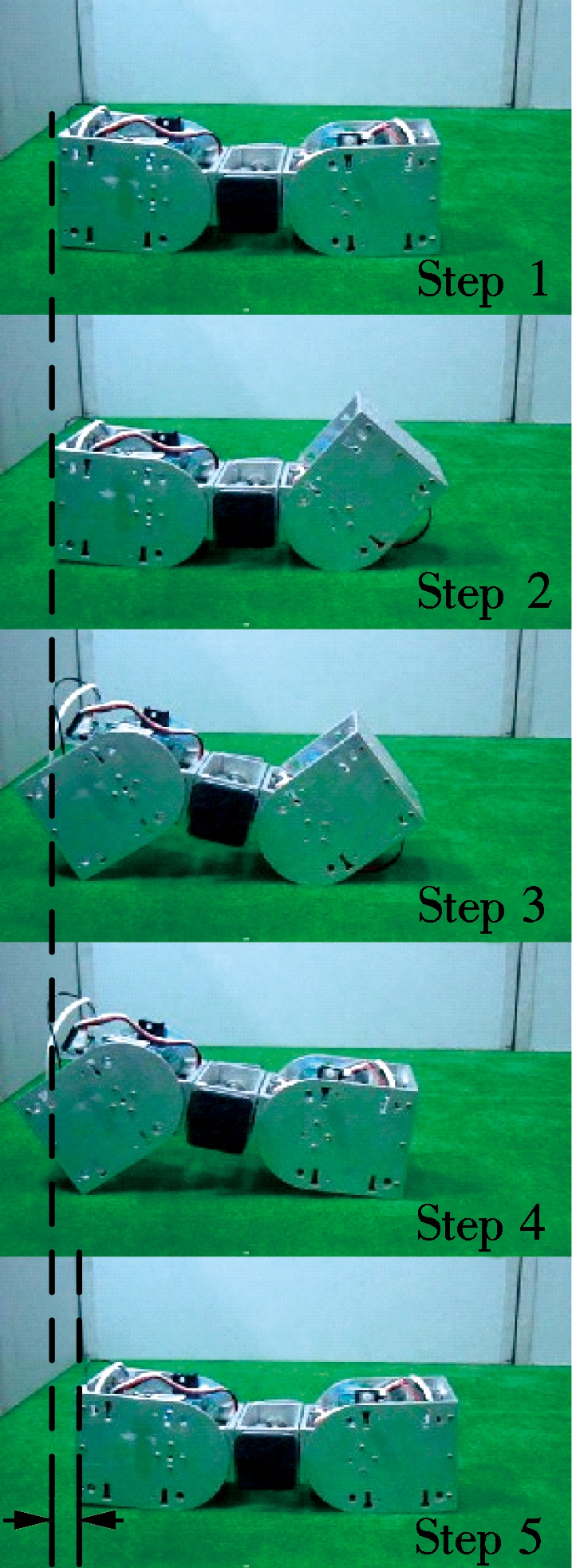 (b)
(b) 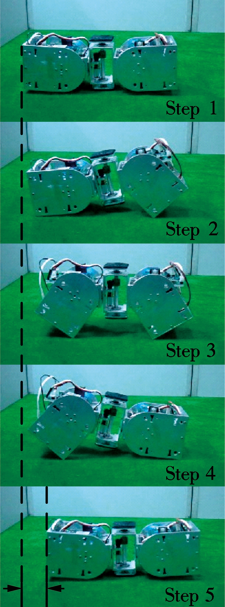 (c)
(c) 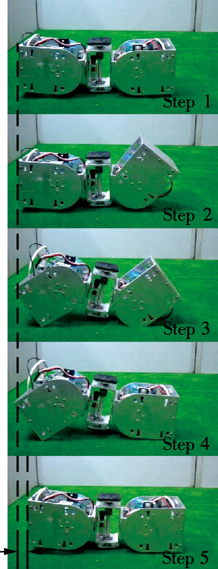 (d)
(d)