
(a)
Abstract:An accurate finite element (FE) model was constructed to examine the hysteretic behavior of double-skin steel-concrete composite box(DSCB) piers for further understanding the seismic performance of DSCB piers; where the local buckling behavior of steel tubes, the confinement of the in-filled concrete and the interface action between steel tube and in-filled concrete were considered. The accuracy of the proposed FE model was verified by the bidirectional cyclic loading test results. Based on the validated FE model, the effects of some key parameters, such as section width to steel thickness ratio, slenderness ratio, aspect ratio and axial load ratio on the hysteretic behavior of DSCB piers were investigated. Finally, the skeleton curve model of DSCB piers was proposed. The numerical simulation results reveal that the peak strength and elastic stiffness decrease with the increase of the section width to steel thickness ratio. Moreover, the increase of the slenderness ratio may result in a significant reduction in the peak strength and elastic stiffness while the ultimate displacement increases. The proposed skeleton curve model can be taken as a reference for seismic performance analyses of the DSCB piers.
Key words:double-skin steel-concrete composite box (DSCB) pier; finite element analysis; local buckling; hysteretic behavior; skeleton curve model
Thin-walled circular or rectangular concrete-filled steel tubular (CFT) columns are increasingly used for highway bridge piers because of their excellent seismic performance under a multi-hazard environment. It was observed by numerous experimental studies[1-4] that the strength, ductility and energy dissipation capacity of CFT columns were considerably improved by filling concrete into the hollow spaces of the steel tubes. The improved strength and ductility of CFT columns can be primarily attributed to the complicated interaction between the steel tube and the in-filled concrete, i.e., the local buckling of the steel tube restrained by the in-filled concrete and the strength enhancement of the in-filled concrete confined by the surrounding steel tube.
In recent decades, some numerical models[5-7] have been proposed to predict the hysteretic behavior of CFT columns. However, most of the existing models were based on the composite beam theory, such as the concentrated plasticity model, the distributed plasticity model and the moment-curvature model. Due to the limitation of the theory assumptions, these numerical models cannot directly consider the local buckling behavior of the steel tubes, the confinement of the in-filled concrete, and the interface action between the steel tube and in-filled concrete. Some researchers have discovered the above simulation limitations, and developed some new simulation models. Schneider[8] utilized ABAQUS to investigate the behavior of CFT columns under axial compression using gap elements to simulate the contact behavior between steel tube and core concrete. Goto et al.[9-11] presented an FE model for thin-walled CFT columns, where the local buckling of steel tubes, the nonlinear behavior of confined concrete, and the steel-concrete interface action can be simultaneously considered. Deng et al.[12] carried out theoretical and numerical research to study the CFSTs and post-tensioned CFSTs under flexural load. The concrete properties were modeled using the Drucker-Prager plasticity model, while the behavior of steel tube was modeled as elastic-perfect plastic. Yousuf et al.[13-15] investigated the transverse impact resistance of the hollow and concrete filled steel square tube columns with ABAQUS. Shakir et al.[16] presented a three-dimensional nonlinear finite element analysis using ABAQUS/Explicit for CFST columns subjected to lateral impact load.
A new type of rectangular CFT member, which is referred to as the double-skin steel-concrete composite box (DSCB) piers, is proposed. It can be regarded as an ideal alternative for high piers of large-span bridges. To study the hysteretic behavior of the proposed DSCB piers, an experimental program was conducted and the test results were represented and discussed in PartⅠof the series papers[17]. The objective of the present paper is to propose a reliable and effective FE model to study the hysteretic behavior of DSCB piers. The accuracy of the proposed FE model was verified by the results from the bidirectional cyclic loading testing. Based on the validated FE model, the hysteretic behaviors of DSCB piers under bidirectional cyclic loading were examined. The effects of some key parameters, such as section width to steel thickness ratio ρ, slenderness ratio λ, aspect ratio χ, and axial load ratio n on the hysteretic behavior of DSCB pier were extensively analyzed and discussed.
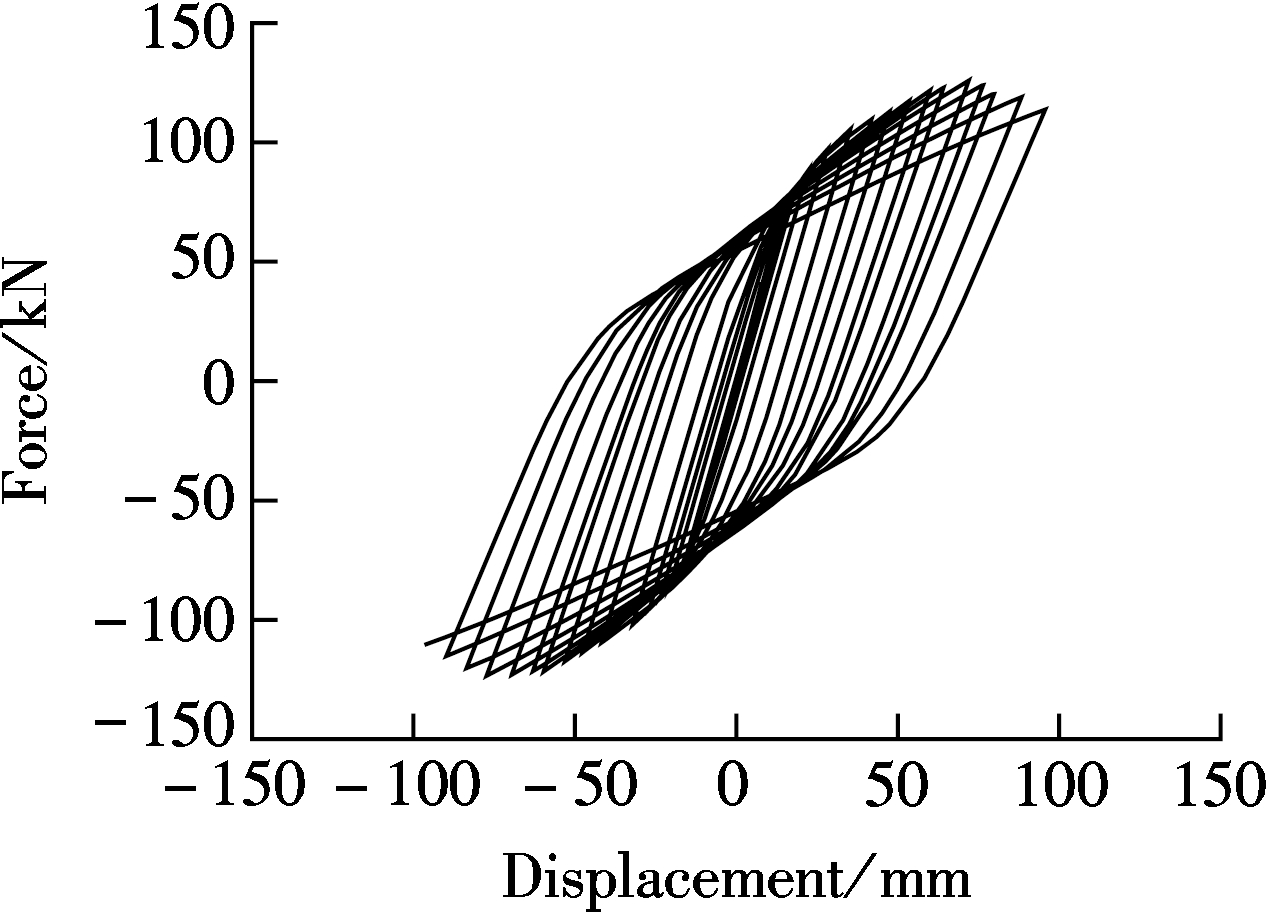
According to the results of the cyclic loading test[17], it can be found that the horizontal load versus displacement hysteretic curves of DSCB piers exhibit a characteristic pinching behavior, as shown in Fig.1(a). This hysteresis loop shows a recovery and degradation in stiffness in the cyclic loading process. It may be caused by the closing and opening of transverse cracks in the in-filled concrete, similar to the elucidated mechanism for pinching hysteretic behavior of CFT columns by Goto et al[9, 11]. When the horizontal displacement decreased from state 1 to zero (see Fig.1), the transverse cracks closed in the compression side will open due to the reduction in the compressive
(a)
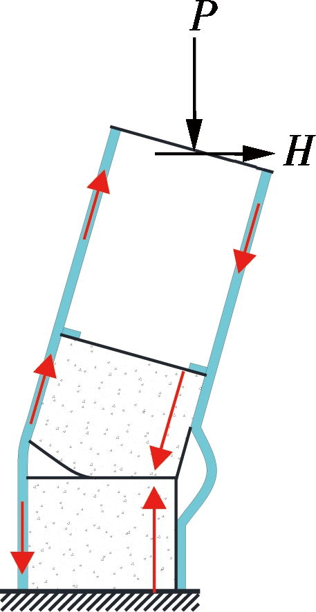
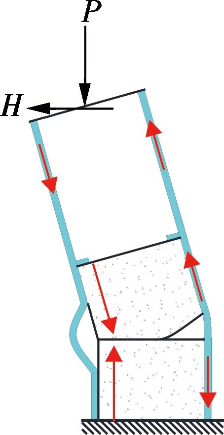
(b) (c) (d)Fig.1 Pinching behavior and local buckling restraining of DCSB piers. (a) Typical load-displacement hysteretic curve of DSCB piers; (b) State 1; (c) State 2; (d) State 3
of the in-filled concrete and the slope of the hysteretic stress at state 2. This results in the stiffness degradation curve becomes smaller. However, in contrast to the unloading process, the DSCB pier recovers its stiffness when the horizontal displacement increases from zero to state 3 in the reverse direction. This is because the transverse cracks opened in state 2 close again under the compressive force in state 3.
Another typical feature of DSCB piers under cyclic loading is the local buckling restraining behavior of steel tubes, which is primarily caused by the change of the axial force distribution on the composite section. Before the occurrence of local buckling in the steel tube, the steel tube carried both the compressive force and the tensile force, which can be calculated by the elementary composite beam theory. After the local buckling occurs in the steel tube, the compressive stiffness of the steel tube decreases gradually, and accordingly, most of the compressive force once carried by the steel tube transfers to the in-filled concrete. With the increase of the displacement amplitude, a tensile force is generated on the steel tube. Because of the transverse cracks, the in-filled concrete cannot carry the tensile force. Thus, the tensile force acting on the steel tube is larger than the compressive force, and the local buckling deformation of the compressive steel tube is stretched, as from state 1 to state 3 shown in Fig.1.
To extensively examine and accurately grasp the hysteretic behavior of DSCB piers, the typical pinching behavior and local buckling restraining behavior of DSCB piers under bidirectional cyclic loading should be properly considered in the numerical model.
2.1 Modeling of steel tube
Since the hysteretic behavior of DSCB piers is greatly influenced by the local buckling restraining behavior of the steel tube, it is necessary to use an element that can take into account the geometrical and the material nonlinearities to model the steel tube. The inelastic constitutive model for steel usually can be classified into the isotropic hardening model and the kinematic hardening model, and the kinematic hardening model can be divided into a linear model and nonlinear model[18]. In the presented model, the material property of the steel tube is defined by the metal combined hardening plasticity in ABAQUS[18]. The combined hardening plasticity belongs to the nonlinear kinematic hardening model. It combines the isotropic and the kinematic hardening models so that it can be degenerated to the two aforementioned models. The yield surface of this model can be expanded, contracted, or translated and the Bauschinger effect can also be considered.
2.2 Modeling of in-filled concrete
Three kinds of concrete constitutive models are commonly used in numerical simulations, and they are the brittle cracking model, the concrete smeared cracking model, and the concrete damaged plasticity model[18]. The brittle cracking model merely takes the tensile nonlinear behavior into account. The concrete damaged plasticity model can take the material damage, cracks developing, cracks closure, and stiffness recovery into account. This makes it more suitable for simulating concrete reaction under bidirectional cyclic loading. Therefore, the concrete damaged plasticity model is adopted here to reflect the concrete properties subjected to cyclic loading.
2.3 Interface contact modeling between steel and in-filled concrete
There are two interfaces in the DSCB piers, i.e., the interface between the outer surface of in-filled concrete and the inner surface of the external steel tube, and the interface between the inner surface of in-filled concrete and the outer surface of the internal steel tube. To accurately simulate the interface contact between the steel tube and the in-filled concrete, appropriate models should be used to represent the contact behavior of steel-concrete interfaces. When two surfaces come into contact, contact pressure occurs in the normal direction and frictional stress occurs in the direction tangential to the contact surface. The contact pressure is calculated using the hard contact pair model implemented in ABAQUS[18]. When the gap of two separated surfaces is closed, the contact pair can transmit contact pressure at the interface. If the nodes of the contact pair are subject to a tensile force, the contact surface will not separate before the tensile stress increases to the bond strength. After the tensile stress exceeds the bond strength, a gap will be generated between the contact pairs. The friction behavior is represented by the Coulomb friction model implemented in ABAQUS. The contact surfaces can carry the shear stress up to the critical shear stress τcr before slipping. The critical shear stress τcr is calculated as τcr=μp, where μ is the friction coefficient and p is the contact pressure. If the shear stress reaches the critical shear stress τcr, slip displacement occurs between the contact surfaces and a shear stress τcr comes to act on the interfaces. The coefficient of the Coulomb friction model between the steel and the in-filled concrete can be taken as μ=0.25[19-20].
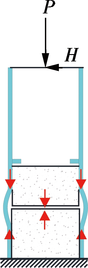
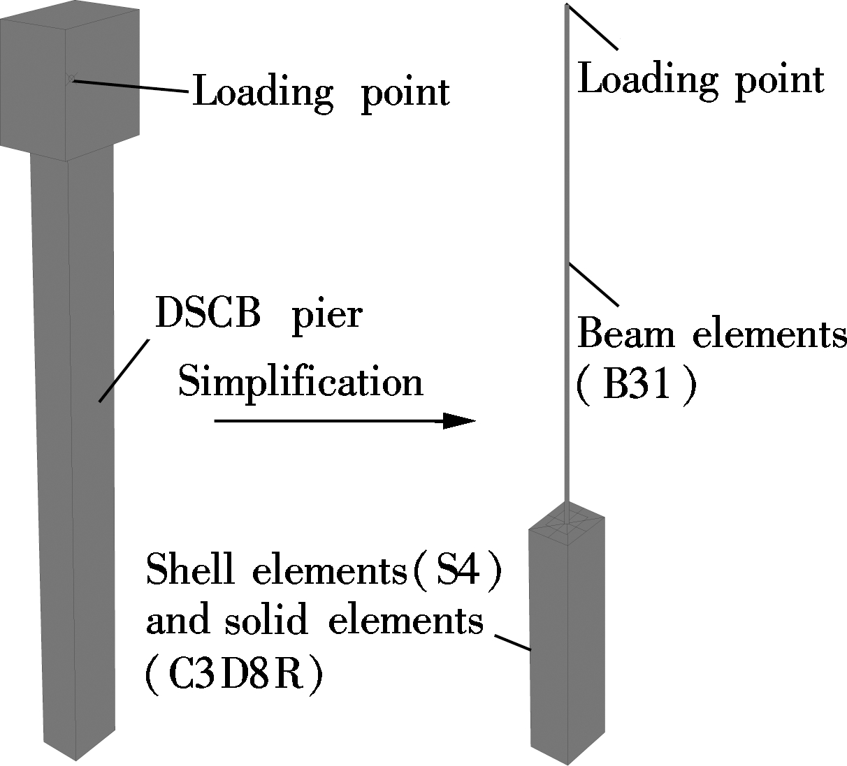
The geometrical and material nonlinear FE model for DSCB pier specimens under cyclic loading was constructed with the finite element software ABAQUS[19]. In order to simulate the main features of DSCB piers under cyclic loading accurately, and reduce the computational cost and improve the convergence efficiency at the same time, the FE model is simplified as schematically shown in Fig.2(a). The lower part of the steel tube is modeled with the 4-node thick shell element (S4). A very fine mesh with the smallest element of dimensions 30 mm×80 mm is used to discretize this region to accurately simulate the local buckling behavior at the lower part of the steel tube, as shown in Fig.2(b). The in-filled concrete core is represented by the 8-node solid element with reduced integration (C3D8R), while the upper part of the piers is modeled with the elastic beam element (B31). At the joint between the upper part and the lower part of the FE model, all nodes of the shell elements and solid elements on this section are coupled to a single node of the beam element. The loading and boundary conditions of the FE model are the same as those in the experimental program, i.e., the bottom of the model is fixed and the lateral cyclic loads are applied at the loading point by the displacement control method with an axial load applied to the top of the FE model and keeping constant.
(a)
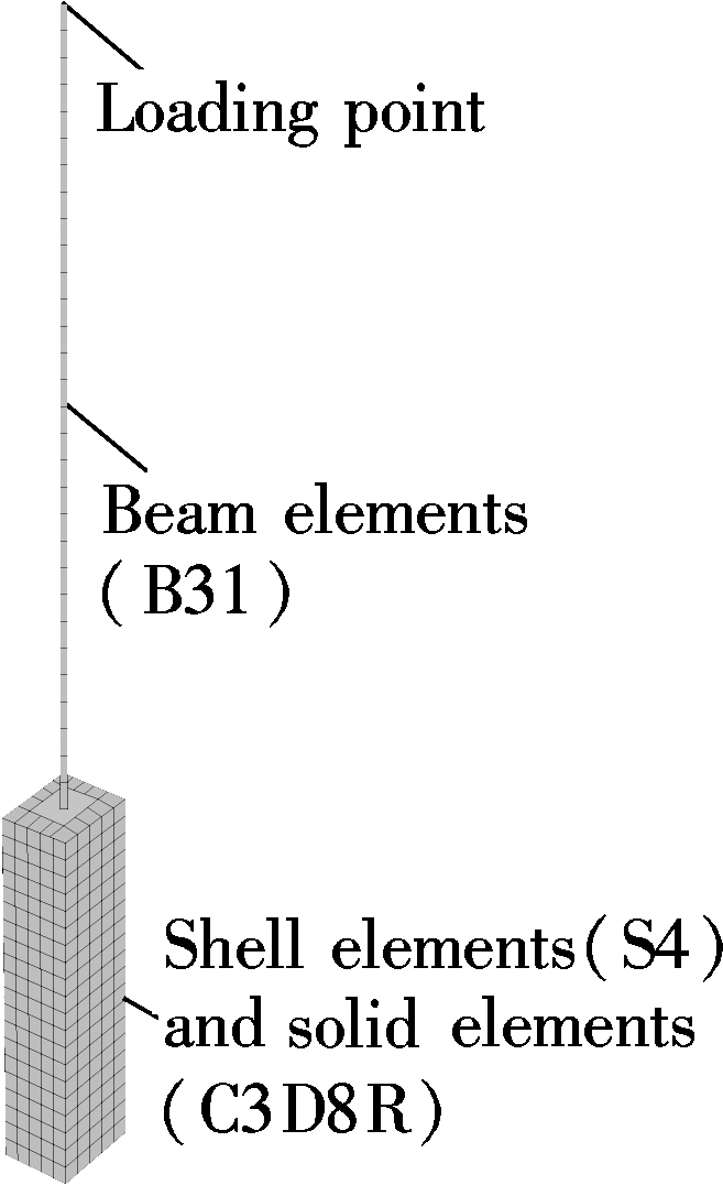
(b)
Fig.2 FE model for DSCB pier specimens. (a) Simplification of FE model; (b) Meshing of FE model
3.2 Verification and discussion
The hysteretic behaviors of DSCB pier specimens were computed by the above nonlinear FE model. In order to validate the accuracy and applicability of the presented FE model, the failure modes and hysteretic curves of DSCB pier specimens obtained by the FE analyses were compared with those from the experimental program.
3.2.1 Failure modes
The typical failure modes of DSCB pier specimen B4-A1-10-4 obtained by the FE analysis are shown in Fig.3, in comparison with those captured from the testing. It can be seen that the simulated local buckling deformation of the steel tube at the lower part of pier specimens is very similar to those observed during testing. This indicates that the presented FE model can accurately predict the failure modes of the DSCB piers.
(a)

(b)
Fig.3 Comparisons of failure modes of DSCB pier specimens from experiment and analysis. (a) FE analysis result; (b) experimental observation
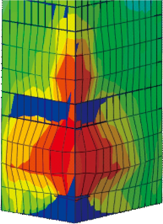
3.2.2 Confinement effect
A typical stress state of a cross section of the in-filled concrete is shown in Fig.4. It shows that the magnitude of the stress has exceeded the defined ultimate strength of unconfined concrete. Fig.5 presents the time-history curve of concrete stress in the corner point at the bottom of the pier where the material suffered the maximum loading. It can be seen that the maximum stress of concrete increases gradually until it exceeds the fracture strength of concrete. After the concrete is crushed, the maximum stress decreases gradually due to the strength reduction. This indicates that the material strength of the in-filled concrete has been enhanced due to the confinement effect provided by the steel tubes.
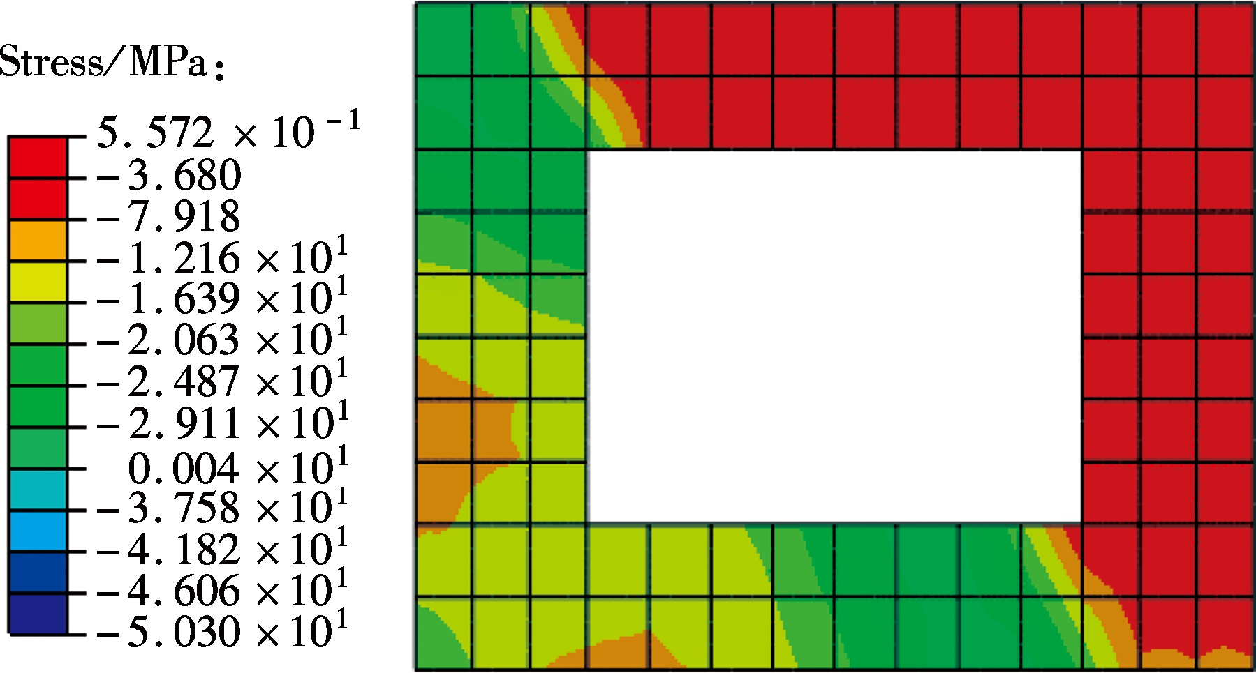
Fig.4 Typical normal stress state of in-filled concrete
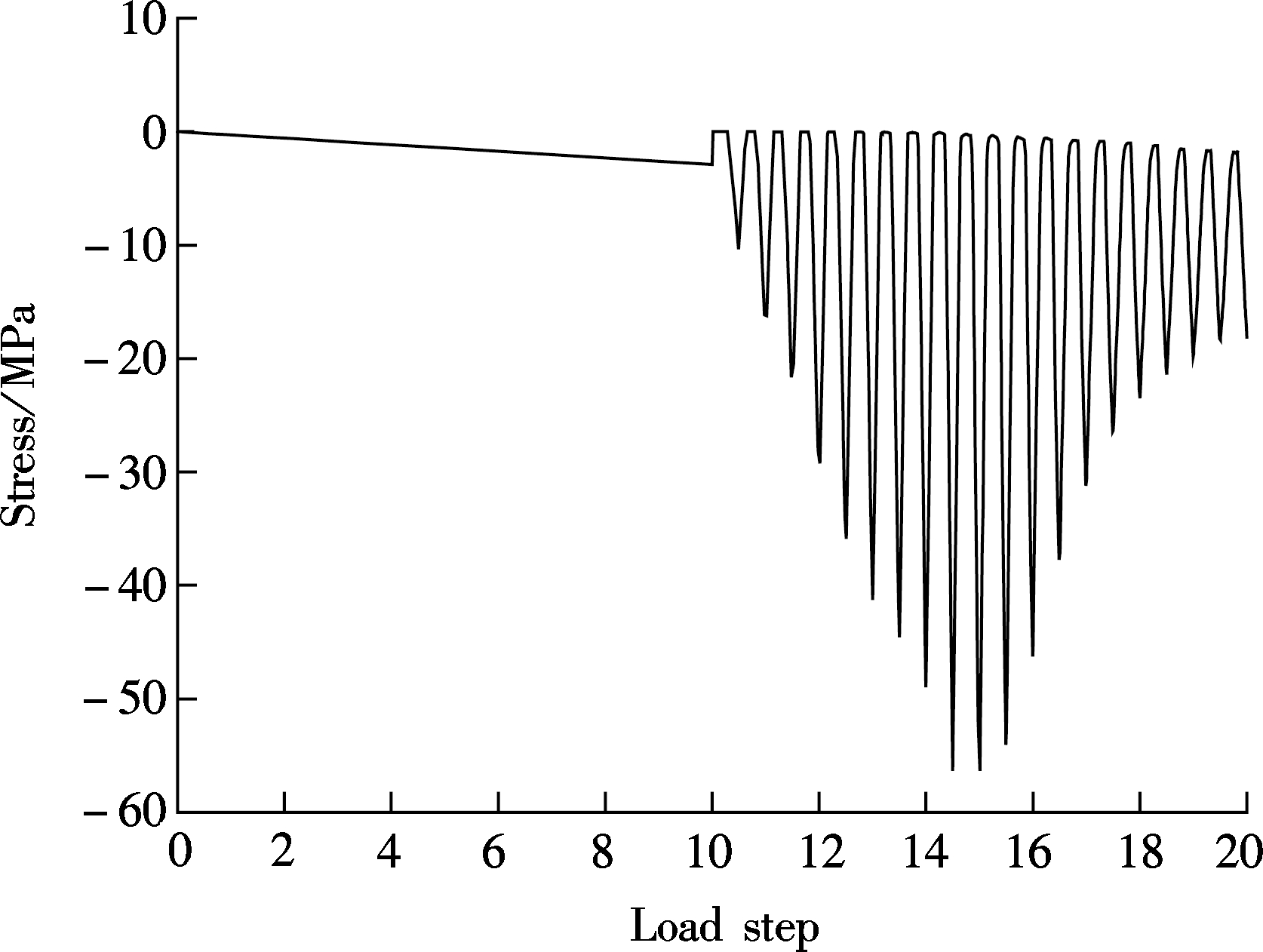
Fig.5 Time-history curve of concrete normal stress in the corner at the bottom of the pier
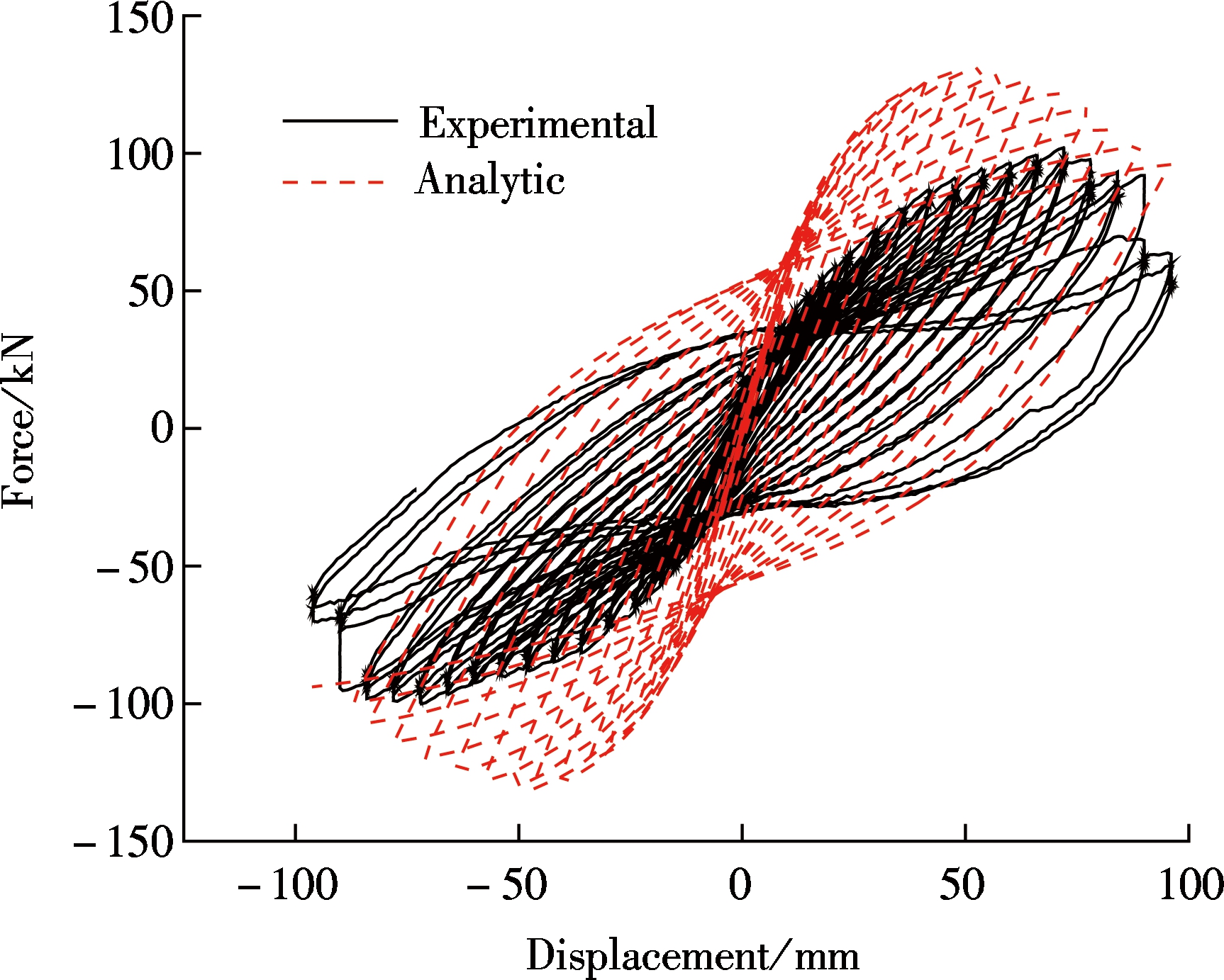
3.2.3 Hysteretic curves
Fig.6 shows the comparison between hysteretic curves of B4-A1-10-4 obtained from the FE model and the test results in terms of the horizontal load-displacement relations. Comparisons in other specimens have come to similar results. It can be observed from the comparisons that the calculated hysteretic curves and the experimental results are in good agreement. However, the FE model slightly overestimates the post peak negative stiffness of the envelopes of the hysteretic curves. This is because the cracks in the steel tubes due to ductile metal fractures are not taken into consideration in the FE model. Besides, for the specimens under bi-directional cyclic loading, the hysteretic curves in the X direction fit better than those in the Y direction. This is because of the coupling effect of the bi-directional cyclic loading. Generally speaking, the presented FE model has an acceptable accuracy in predicting the hysteretic behavior of DSCB piers under both uni-directional and bi-directional cyclic loading.
To further understand the seismic performance of DSCB piers under bi-directional cyclic loading, the parametric effects on the hysteretic behavior of DSCB piers, concerning the key parameters, such as section width to steel thickness ratio ρ, slenderness ratio λ, aspect ratio χ, and axial load ratio n, were analyzed using the presented FE model in this section. The parameters of the simulated model set as benchmark specimen are ρ=0.112, λ=0.993, χ=1.375, n=0.20. Each parameter is discussed in the course of fixing the other parameters.
4.1 Effect of section width to steel thickness ratio ρ
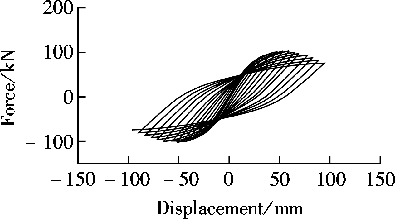
To determine the effect of section width to steel thickness ratio ρ on the hysteretic behavior of DSCB piers, steel thickness is varied from 4 to 10 mm while the other parameters remain fixed. The horizontal hysteretic curves of DSCB piers for three steel thicknesses are given in Fig.7 to qualitatively demonstrate the variation tendency with different ρ. It can be observed that the pinching behavior gradually disappears and the hysteretic loop becomes plumper with the decrease of ρ. Horizontal envelope curves with different ρ are shown in Fig.8. It is found that ρ has a considerable effect on the peak strength and the elastic stiffness, while there is no significant change in the ultimate displacement.

4.2 Effect of slenderness ratio λ
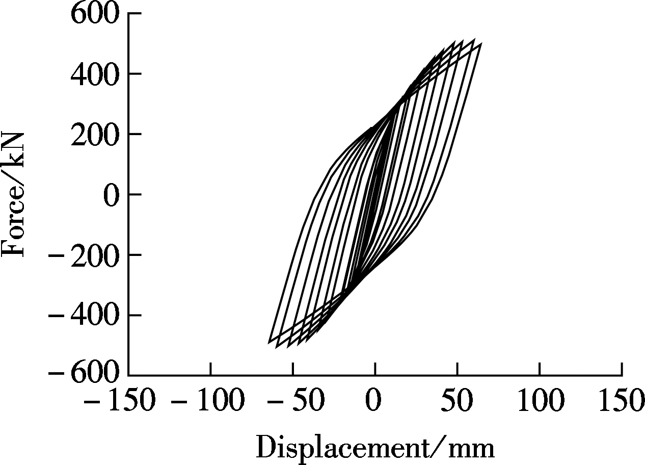
The influence of the slenderness ratio λ on the hysteretic behavior of DSCB piers is studied hy changing the pier height from 2 to 8 m. Fig.9 shows the hysteretic curves of DSCB piers for three pier heights to qualitatively demonstrate the variation tendency with different λ. It can be observed that the pinching behavior gradually disappears and the hysteretic loop becomes plumper with the increase of λ. The effect of λ on horizontal envelope curves is presented in Fig.10. It can definitely be seen that increasing λ results in a significant reduction in the peak strength and the elastic stiffness with an obvious increase in the ultimate displacement. However, when the DSCB pier is relatively slender (λ>1.44), λ has less influence on the hysteretic behavior.
4.3 Effect of aspect ratio χ
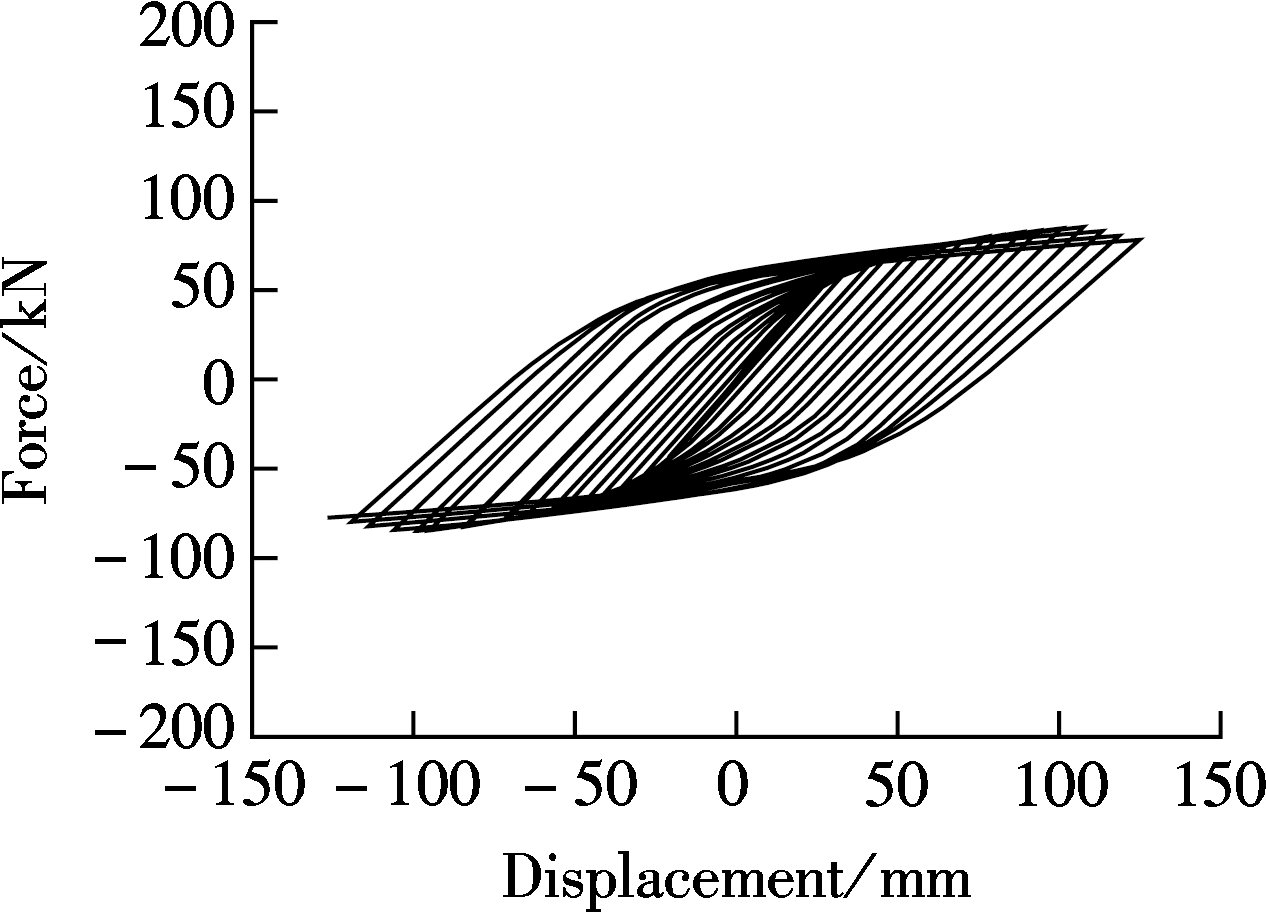
The effect of the aspect ratio χ of the pier section on the hysteretic behavior of DSCB piers is additionally investigated. χ varied from 1.375 to 2.625 through the variation of width B1 from 440 to 840 mm for the same width D1 of 320 mm. The horizontal hysteretic curves of DSCB piers with differentχ are shown in Fig.11. It can be noticed from the figures that the pinching behavior of the hysteretic loop becomes more obvious in the Y direction with the increase of χ. The horizontal envelope curves with different χ are presented in Fig.12. The results clearly indicate that the increase of χ significantly improves the peak strength and the elastic stiffness in the X direction while the ductility decreases. This is because the increase of width B1 significantly increases the flexural stiffness in the X direction.
4.4 Effect of axial load ratio n
The effect of the axial load ratio n is discussed in the range of 0.1 to 0.3. The horizontal hysteretic curves of DSCB piers with different n are shown in Fig.13. It can be noticed from the figures that the pinching behavior of the hysteretic loop becomes more obvious with the increase of n. The horizontal envelope curves with different n are presented in Fig.14. It is found that n has little effect on the peak strength and the degradation stiffness, while there is no significant change in the ultimate displacement.


Based on the experimental results and numerical analyses, a tri-linear hysteretic model is proposed to reflect the nonlinear ability of DSCB piers, as schematically shown in Fig.15. The three characteristic points of the tri-linear skeleton curve correspond to the yield point A, the peak load point B, and the ultimate displacement point C. Py, Pm and Pu are the yield load, peak load, and ultimate load, respectively; Δy, Δm and Δu are the displacements corresponding to Py, Pm and Pu, respectively.
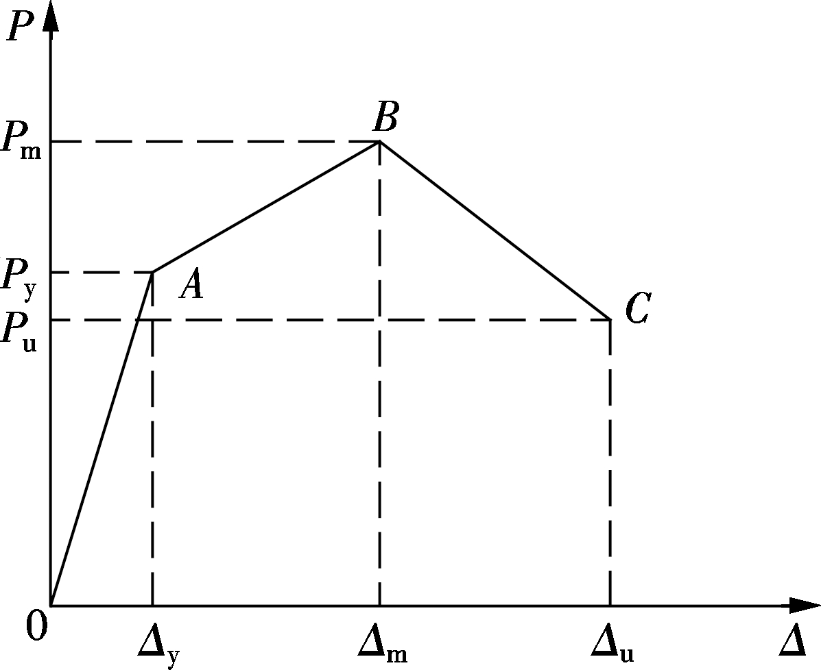
Fig.15 Simplified skeleton curve of DSCB piers and characteristic points
5.1 Determination of elastic stiffness, hardening stiffness and degradation stiffness
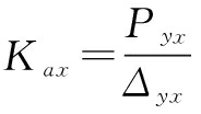
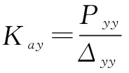
There is no clear crack point in the experimental load-displacement curve, so the skeleton curve of DSCB piers before yielding is simplified as a line connecting the origin point O and the yield point A, and the elastic stiffness Kax in the X direction and Kay in the Y direction can be defined as
(1)
(2)
Due to the complexity of the geometrical and material nonlinearity of DSCB piers, it is difficult to obtain the hardening stiffness and the degradation stiffness through theoretical analysis. Thus, with the experimental data and numerical analysis results, the statistic regression method is employed to obtain the hardening stiffness and the degradation stiffness corresponding to AB and BC in Fig.15. The regression parameters include ρ, λ, and n.
By regression analysis, the following equations can be acquired to calculate the hardening stiffness Kpx in the X direction and Kpy in the Y direction:
Kpx= -23.28n2+4.70λ2-66.72ρ2-548.22nλ-
7.63nρ-467.18λρ+555.27n+147.27λ+
484.02ρ-152.54
(3)
Kpy= 28.91n2+1.31λ2+52.58ρ2-19.67nλ-23.87nρ+
1.29λρ+11.01n+0.25λ-16.86ρ+2.17
(4)
The degradation stiffness Kdx in the X direction and Kdy in the Y direction can be obtained by
Kdx= -113.86n2-0.44λ2-123.95ρ2-320.96nλ-
254.33nρ-285.97λρ+401.94n+98.01λ-
369.40ρ-111.70
(5)
Kdy= 28.91n2+1.31λ2+52.58ρ2-19.67nλ-
23.87nρ+1.29λρ+11.01n+0.25λ-16.86ρ+2.17
(6)
5.2 Verification of the proposed skeleton curve model
Based on the established skeleton curve model, the load-displacement skeleton curves of several typical specimens[17] were calculated and compared with those of the test results, as shown in Fig.16. It can be seen that the theoretical skeleton curves obtained by the proposed skeleton curve model agree well with those from the test. This demonstrates that the proposed skeleton curve model can appropriately express the nonlinear behavior of DSCB piers and can be taken as a reference for the seismic performance analyses of DSCB piers.
1) The constructed FE model can accurately predict the hysteretic behavior of DSCB piers under both uni-directional and bi-directional cyclic loading.

2) The peak strength and the elastic stiffness increase with the decrease of the section width to steel thickness ratio ρ, while there is no significant change in the ultimate displacement.
3) The increase of the slenderness ratio λ results in a significant reduction in the peak strength and elastic stiffness while an obvious increase in the ultimate displacement. However, when the DSCB pier is relatively slender (λ>1.44), the slenderness ratio λ has less influence on the hysteretic behavior.
4) The increase of the aspect ratio χ significantly improves the peak strength and the elastic stiffness in the X direction while the ductility decreases.
5) The axial load ratio n has a little effect on the peak strength and the degradation stiffness, while having no obvious effect on the ultimate displacement, when n is smaller than 0.3.
6) A tri-linear skeleton curve model of DSCB piers is proposed, which can be taken as a reference for seismic performance analyses of DSCB piers.
References:
[1]Ge H B, Usami T. Cyclic tests of concrete-filled steel box columns[J]. Journal of Structural Engineering, 1996, 122(10): 1169-1177.
[2]Marson J, Bruneau M. Cyclic testing of concrete-filled circular steel bridge piers having encased fixed-based detail[J]. Journal of Bridge Engineering, 2004, 9(1): 14-23.
[3]Han L H, Huang H, Tao Z, et al. Concrete-filled double skin steel tubular (CFDST) beam-columns subjected to cyclic bending[J]. Engineering Structures, 2006, 28(12): 1698-1714. DOI:10.1016/j.engstruct.2006.03.004.
[4]Goto Y, Jiang K S, Obata M. Stability and ductility of thin-walled circular steel columns under cyclic bidirectional loading[J]. Journal of Structural Engineering, 2006, 132(10): 1621-1631.
[5]Hajjar J F, Molodan A, Schiller P H. A distributed plasticity model for cyclic analysis of concrete-filled steel tube beam-columns and composite frames[J]. Engineering Structures, 1998, 20(4/5/6): 398-412.
[6]Susantha K A S, Ge H B, Usami T. Cyclic analysis and capacity prediction of concrete-filled steel box columns[J]. Earthquake Engineering & Structural Dynamics, 2002, 31(2): 195-216.
[7]Tort C, Hajjar J F. Mixed finite-element modeling of rectangular concrete-filled steel tube members and frames under static and dynamic loads[J]. Journal of Structural Engineering, 2010, 136(6): 654-664.
[8]Schneider S P. Axially loaded concrete-filled steel tubes[J]. Journal of Structural Engineering, 1998, 124(10): 1125-1138.
[9]Goto Y, Kumar G P, Kawanishi N. Nonlinear finite-element analysis for hysteretic behavior of thin-walled circular steel columns with in-filled concrete[J]. Journal of Structural Engineering, 2010, 136(11): 1413-1422.
[10]Goto Y, Kumar G P, Seki K. Finite element analysis for hysteretic behavior of thin-walled CFT columns with large cross sections[J]. Procedia Engineering, 2011, 14: 2021-2030. DOI:10.1016/j.proeng.2011.07.254.
[11]Goto Y, Mizuno K, Kumar G P. Nonlinear finite element analysis for cyclic behavior of thin-walled stiffened rectangular steel columns with in-filled concrete[J]. Journal of Structural Engineering, 2012, 138(5): 571-584.
[12]Deng Y, Tuan C Y, Xiao Y. Flexural behavior of concrete-filled circular steel tubes under high-strain rate impact loading[J]. Journal of Structural Engineering, 2012, 138(3): 449-456.
[13]Yousuf M, Uy B, Tao Z, et al. Behaviour and resistance of hollow and concrete-filled mild steel columns due to transverse impact loading[J]. Australian Journal of Structural Engineering, 2012, 13(1): 65-80.
[14]Yousuf M, Uy B, Tao Z, et al. Transverse impact resistance of hollow and concrete filled stainless steel columns[J]. Journal of Constructional Steel Research, 2013, 82: 177-189. DOI:10.1016/j.jcsr.2013.01.005.
[15]Yousuf M, Uy B, Tao Z, et al. Impact behaviour of pre-compressed hollow and concrete filled mild and stainless steel columns[J]. Journal of Constructional Steel Research, 2014, 96: 54-68. DOI:10.1016/j.jcsr.2013.12.009.
[16]Shakir A S, Guan Z W, Jones S W. Nonlinear finite element analysis of concrete filled steel tube (CFST) columns under projectile impact loading[C/OL]//The 5th International Conference on Computational Methods. Cambridge, UK, 2014. http://www.sci-en-tech.com/ICCM2014/PDFs/312-921-1-PB.pdf.
[17]Xia J, Zong Z H, Xu C R, et al. Study on seismic performance of double-skin steel-concrete composite box piers: Part Ⅰ—Bidirectional quasi-static test [J]. Journal of Southeast University (English Edition), 2016, 32(1): 58-66.
[18]Hibbitt D, Karlsson B, Sorenson P. ABAQUS version 6.4: Theory manual, users’ manual, verification manual and example problems manual [M]. Pawtucket, RI, USA: Hibbitt, Karlson & Sorenson Inc., 2003.
[19]Baltay P, Gjelsvik A. Coefficient of friction for steel on concrete at high normal stress[J]. Journal of Materials in Civil Engineering, 1990, 2(1): 46-49.
[20]Huang H. Behavior of concrete filled double-skin steel tubular beam-columns[D]. Fuzhou: School of Civil Engineering, Fuzhou University, 2006. (in Chinese)
Citation:Xia Jian, Zong Zhouhong, Xu Chaoran, et al. Seismic performance of double-skin steel-concrete composite box piers: PartⅡ—Nonlinear finite element analysis[J].Journal of Southeast University (English Edition),2016,32(3):346-355.DOI:10.3969/j.issn.1003-7985.2016.03.015.
DOI:10.3969/j.issn.1003-7985.2016.03.015
摘要:为进一步研究双壁钢箱混凝土组合墩柱(DSCB墩柱)的抗震性能,建立了考虑钢管局部屈曲、内填混凝土约束效应和钢管与混凝土接触作用的DSCB墩柱的精细化有限元模型.首先通过双向拟静力试验结果验证了该有限元模型的准确性;然后采用验证后的有限元模型,研究了钢板宽厚比、长细比、截面宽高比、轴压比等关键参数对DSCB墩柱滞回性能的影响;最后根据试验和有限元分析结果提出了DSCB墩柱的骨架曲线模型.数值模拟分析结果表明:随着钢板宽厚比的增大,DSCB墩柱的峰值强度和弹性刚度减小;随着长细比的增加,DSCB墩柱的峰值强度和弹性刚度明显降低,而极限位移则随之增大.所提出的骨架曲线模型可为DSCB墩柱的抗震性能分析提供参考.
关键词:双壁钢箱混凝土组合墩柱; 有限元分析; 局部屈曲; 滞回性能; 骨架曲线
中图分类号:U443.22
Received:2016-01-12.
Foundation item:s:The National Natural Science Foundation of China (No. 51678141, 51378112), the Open Fund from the National Engineering Laboratory for Technology of Geological Disaster Prevention in Land Transportation, Southwest Jiaotong University (No. SWJTU-GGS-2014001).
Biographies:Xia Jian (1970—), male, doctor, professor; Zong Zhouhong (corresponding author), male, doctor, professor, zongzh@seu.edu.cn.