Fig.1 Contact between ball and inner ring
Abstract:In order to more accurately predict the contact fatigue life of rolling bearing, a prediction method of fatigue life of rolling bearing is proposed based on elastohydrodynamic lubrication (EHL), the 3-parameter Weibull distribution and fatigue strength. First, the contact stress considering elliptical EHL is obtained by mapping film pressure onto the Hertz zone. Then, the basic strength model of rolling bearing based on the 3-parameter Weibull distribution is deduced by the series connection reliability theory. Considering the effect of the type of stress, variation of shape and fluctuation of load, the mathematical models of theP-S-N curve of the minimum life and the characteristic life for rolling bearing are established, respectively, and thus the prediction model of fatigue life of rolling bearing based on the 3-parameter Weibull distribution and fatigue strength is further deduced. Finally, the contact fatigue life obtained by the proposed method and the latest international standard (ISO281: 2007) about the fatigue life prediction of rolling bearing are compared with those obtained by the statistical method. Results show that the proposed prediction method is effective and its relative error is smaller than that of the latest international standard (ISO281: 2007) with reliability R> 0.93.
Key words:rolling bearing; 3-parameter Weibull distribution; elastohydrodynamic lubrication (EHL); fatigue strength; contact fatigue life
Contact fatigue failure, a kind of fault caused by the alternating stress, is one of the most common failure modes among various rolling bearings. Bearing fault may result in failure of machine or even major accident, so it is of great importance to accurately predict the time when rolling bearing fails to work, namely the contact fatigue life. Early in 1939, Weibull put forward that fatigue cracks first appeared at the point of the maximum shear stress under the rolling surface and then extended to the surface to generate fatigue flakes[1-2]. Besides, he also pointed out the relationship among survival probability and maximum shear stress, stress cycle times and stress volume. In 1947, Lundberg and Palmgren[3] proposed the famous maximum dynamic shear stress theory and further deduced L-P model formula. The L-P model is the first statistical life model based on fatigue cracks, but its applicability is limited due to the constraints of bearing technology and manufacturing level at that time. However, the L-P model was still widely accepted because it had sufficient precision to assess the fatigue life of rolling bearing in most working conditions. In 1985, Ioannides and Harris[4] put forward a new life theory based on the L-P model. When the loaded parts of bearing withstand a stress which is lower than fatigue limit, the loaded parts will not generate fatigue failure. The theory well explains ultra-long life phenomenon and the model proposed by them was also known as I-H model. The model was simplified as load-life relational expression based on the fatigue life test of rolling bearing due to the complexity of the original I-H life model. In 1996, Tallian[5] presented a new model to predict the life of bearing based on the test results over the past few years about the fatigue life of rolling bearing. The model has many disadvantages, such as too many factors to be considered, inconvenience for application, poor meticulousness in model deduction and many undetermined coefficients, which make the model fail to be applied widely. However, the model further enriched the L-P life theory despite of its limited applications[6-8]. In 2001, Yu and Harris[9] pointed out that fatigue life only had some connection with stress volume, maximum fatigue initial stress and stress cycle times. As well, they also gave mathematical relationships between them based on the fatigue strength of materials and the infinite life of bearings. Currently, the newest fatigue life prediction equation of rolling bearing is still L-P equation based on the maximum dynamic shear stress theory. In spite of its wide application, the life equation also has some deficiency inevitably. For example, it assumes that fatigue life obeys the two-parameter Weibull distribution, ignores the failure of rollers and does not directly introduce material fatigue strength which plays a crucial role in the life of rolling bearing[10-11]. A large number of experiments show that the fatigue life of rolling bearing is more in line with the 3-parameter Weibull distribution. In view of the above issues, a prediction model of fatigue life for rolling bearing is established based on the 3-parameter Weibull distribution and fatigue strength in combination with EHL, contact stress transformation and P-S-N curve. Then, the effectiveness of the proposed model is verified by the comparison of fatigue life which is obtained by using the proposed method, GB/T 6391—2010 and the statistical method, respectively.
1.1 EHL physical model of ball bearing
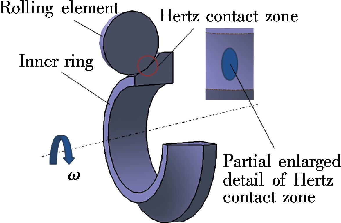
The Hertz contact zone of loaded ball bearing is a tiny elliptical area, as shown Fig.1. Therefore, according to the simplification theory of two contact objects with random shape, contact between the ball and raceway can be replaced with that between elastic spheroid and rigid plane, as shown in Fig.2. x axis is the speed direction of contact point; z axis is the thickness direction of oil film; Rx and Ry are equivalent radii within xz and yz planes, respectively; w is the normal load.
Fig.1 Contact between ball and inner ring

Fig.2 EHL physical model between the ball and raceway
1.2 Calculation of film pressure and contact stress under EHL
Taking a certain type of four-point contact ball bearing for example, its basic parameters are listed in Tab.1.
Assume that lubricant is Newton fluid, the oil film between the ball and raceway is intact in the working conditions and bearing is under isothermal elliptical contact EHL. The EHL equations of ball bearing are shown as follows:
Tab.1 Relevant parameters of four-point contact ball bearing
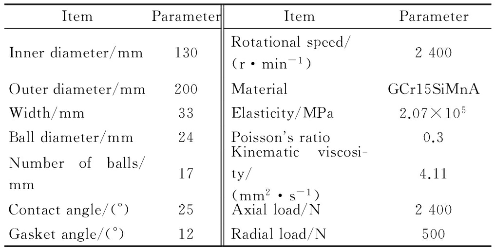
ItemParameterItemParameterInnerdiameter/mm130Rotationalspeed/(r·min-1)2400Outerdiameter/mm200MaterialGCr15SiMnAWidth/mm33Elasticity/MPa2.07×105Balldiameter/mm24Poissonsratio0.3Numberofballs/mm17Kinematicviscosi-ty/(mm2·s-1)4.11Contactangle/(°)25Axialload/N2400Gasketangle/(°)12Radialload/N500
1) Reynolds equation
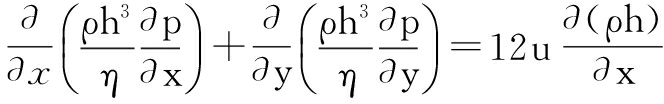
(1)
where ρ and η are the density and viscosity of lubricant, respectively; p and h are the pressure and thickness of the oil film, respectively; u is the average speed of the contact surface between the ball and raceway.
The boundary conditions of the Reynolds equation are as follows:
Oil film entrance side
p(x0,y)=0
Oil film exit side
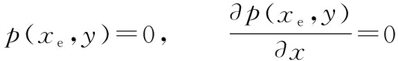
Oil film other side
p(x,y0)=p(x,ye)=0
where x0 and xe are the entrance and exit boundaries of the x direction in the solved field, respectively; y0 and ye are the entrance and exit boundaries of the y direction in the solved field, respectively.
2) Film thickness equation
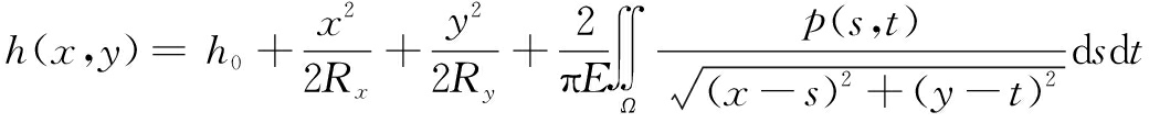
(2)
where h0 is unknown constant; Rx and Ry are the equivalent curvature radii between the ball and raceway at the x and y directions, respectively; E is the equivalent elasticity modulus; s and t are the additional coordinate corresponding to coordinate x and y.
3) Pressure-viscosity equation
Roelands equation with higher precision is applied to the viscosity-pressure relationship of lubricant.
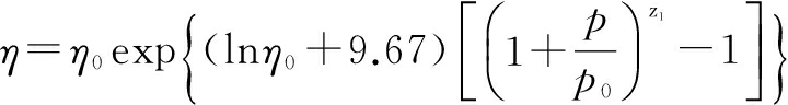
(3)
where η0 is the lubricant viscosity at ambient temperature; p0 is the pressure coefficient; z1 is the mineral oil coefficient, z1=0.68.
4) Pressure-density equation
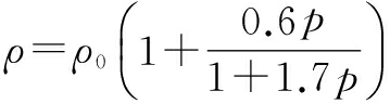
(4)
where ρ0 is the ambient density of lubricant.
5) Load equation

(5)
where w is the external load of the Hertz contact zone.
In order to conveniently analyze and improve the stability of the calculation process, the following 10 dimensionless parameters are introduced:

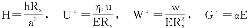
where pH=3w/(2πa2) is the maximum Hertz contact stress; a is the contact half width in the x direction of the contact area; Ptr is the deformation coefficient of elliptical contact; U*, W* and G* are the speed parameter, load parameter and material parameter of dimensional normalization, respectively. Dimensionless parameters above are substituted into the elliptical contact EHL equations, and then the numerical results are obtained by the finite difference method.
In order to make the solution process converge, the solved region of Reynolds equations should be greater than that of Hertz zone. The short side of the rectangular solved region should be twice that of the ellipse rate of the contact zone at least. The rectangular solved region is divided into 113×113 elements by equal net. The pressure distribution of the oil film is obtained by the multi-grid method, as shown in Fig.3. Fig.3(a) is the true 3-dimensional pressure of the oil film, Fig.3(b) is the sectional view of α cross section at x=0. Clearly, there is a peak value of oil film pressure in the lubricant exit, which is in line with the actual cognition.
In the proposed method, oil pressure is the external load of contact stress calculation. According to the physicalmodel between the ball and raceway, the oil film pressure in the entire solved region is mapped to the Hertz contact zone in the software ANSYS, so the contact stress of the ball bearing is obtained under EHL. In order to illustrate the necessity of considering EHL during the calculation of contact stress, the contact stress under different loads is calculated by the proposed method and Hertz method, respectively, as listed in Tab.2. Apparently, the contact stress considering EHL is smaller than Hertz contact stress considering EHL, and their errors are about 20%. The reason is that lubricant EHL effect makes the contact stress between the ball and raceway homogenized under the influence of oil pressure and deformation, and thus the maximum contact stress between the ball and raceway also decreases due to the effect of oil film.
(a)
(b)
Fig.3 Distribution of oil film pressure. (a) 3D view of oil film pressure; (b) View of section α
Tab.2 Comparison of contact stress
Axialload/NContactstress/MPaProposedmethodHertzformulaRelativeerror/%2300653.99811.5919.422400656.26821.0120.072500658.37830.2220.702600666.98839.2220.522700667.99848.0221.23
Under a certain stress level S, the fatigue life of all parts of the rolling bearing obeys the 3-parameter Weibull distribution[12-13]. The reliability calculation equation of part i of bearing is defined as
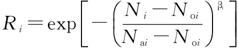
(6)
where Ni is the life (stress cycle times) of part i; Noi is the minimum life of part i; Nai is the characteristic life of part i; βi is the Weibull slope and Ri is the reliability of part i.
Here, assuming that the stress cycle number of part i is ui when the bearing rotates one circle, the stress cycle number of part i in the whole life circle can be expressed as
Ni=uiL
(7)
where L is the life of bearing (million circles).
Substituting Eq.(7) into Eq.(6), we obtain

(8)
According to the characteristic that the whole bearing stops working once a single part of rolling bearing fails to work, the bearing can be regarded as a mechanical system consisting of an inner ring, outer ring and rollers in series. In terms of the reliability laws of the series system[14], the reliability of bearings can be expressed as

(9)
where Z is the number of rolling elements.
Due to the material uniformity of bearing, βi is not with large changes. β1=β2=β3=β can be adopted. Substituting Eq.(8) into Eq.(9), we obtain
![]()
(10)
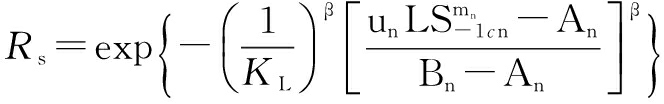
The minimum value of No1/u1, No2/u2 and No3/u3 is expressed with subscript n; then the item with the subscript n in Eq.(10) are extracted to obtain the following equation:
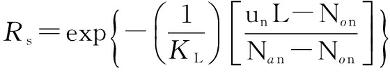
(11)
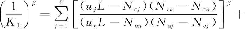

(12)
where KL is the correction coefficient of bearing life.
3.1 Revision of pulsating contact stress
The P-S-N curve of materials is usually obtained by fatigue tests under the stress ratio R=-1(namely, under symmetric cyclic stress), but the actual operating conditions are often different from the test criteria. Therefore, it is necessary to make a transformation. For rolling bearing, actual stress is often the pulsating cyclic stress (R=0), which is inconsistent with test conditions, so the pulsating cyclic stress of bearings must be transformed into symmetric cyclic stress with the same life. Commonly used life transformation methods include the Gerber curve, Goodman line, Soderberg line, Morrow line and Xie Lianxian polyline, etc. The Gerber curve is not used frequently due to its dangerous nature and nonlinear relationship. The Soderberg line is too conservative for most situations. The Goodman line is suitable for brittle metal materials rather than ductile metal materials. In former designs, the Xie Lianxian polyline and Goodman line are more often adopted. The former method is more precise than the latter one, but the fatigue limit σ0 under pulsating cycle must be obtained through the fatigue test. If there are no conditions to conduct fatigue tests, the former method cannot be used[15]. The Morrow line is greatly in accord with the test data and is more accurate than the Goodman line, but it is also relatively conservative to some degree. Considering the security and the accuracy for rolling bearing, the Morrow line is adopted for carrying out equal life transformation towards the actual pulsating cyclic stress of the rolling bearing as follows:

(13)
where Sai is the stress amplitude of part i; Smi is the average amplitude of part i; S-1i is the equivalent contact fatigue stress of part i; σfi is the complete breaking strength of the material of part i(σfi=σbi+350);σbi is the ultimate strength of the material of part i.
3.2 Establishment of P-S-N curve of bearing parts
In fact, the fatigue strength of materials differs from that of actual parts due to the differences between the standard specimen and actual parts in terms of shape, structure, surface processing quality and heat treatment. In order to obtain the fatigue strength of parts, the fatigue strength of materials is often revised. The common expression of the P-S-N curve in the form of power function is
NSα=C
(14)
where α and C are material constants.
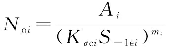
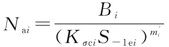
According to Eq.(14), the P-S-N curve equations of the minimum life and characteristic life of bearing material are, respectively, defined as

(15)

(16)
where Ai, Bi, mi and ![]() are material constants; S-1ci is the fatigue stress of the standard specimen.
are material constants; S-1ci is the fatigue stress of the standard specimen.
Due to the differences between the bearing part and standard specimens, the influence of dimension coefficient ε, surface quality coefficient β0, effective stress concentration coefficient Kσ and intensification coefficient βq on the fatigue strength of bearing parts should be considered. According to Ref.[16], the revised equivalent fatigue stress of bearing parts is shown as
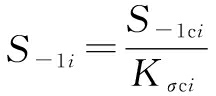
(17)
where Kσci is the comprehensive effect coefficient; S-1i is the equivalent fatigue stress of bearing parts.
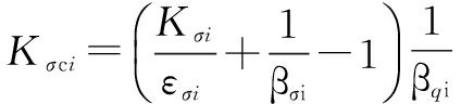
(18)
According to Eqs.(15) to (17), the P-S-N curve equations of the minimum life and characteristic life for bearing parts can be obtained as
(19)
(20)
Material constants mi and ![]() i are determined by tests. For the same material, mi and
i are determined by tests. For the same material, mi and ![]() i are not equal but the difference is not great. Due to the lack of data, it is assumed that mi and
i are not equal but the difference is not great. Due to the lack of data, it is assumed that mi and ![]() i are equal for the convenience of calculation.
i are equal for the convenience of calculation.
Under a double-log coordinate system, the power function equation of the P-S-N curve is linear. The schematic diagram of the P-S-N curve corresponding to bearing material, minimum life and characteristic life are shown in Fig.4.

Fig.4 P-S-N curves of part and material
3.3 Revision of P-S-N curve based on Miner linear cumulative damage law
In fact, rolling bearings working in various machines carry a random load instead of a constant one. The true value of the random load in different working conditions or at different moments may be higher or lower than the fatigue limit load; i.e., the maximum stress of rolling bearing is not always larger than the fatigue limit. Under actual working conditions, the load below the endurance limit also appears frequently, which inevitably has a certain influence on the fatigue damage of parts. The Miner theory based on the linear cumulative damage hypothesis does not consider the stress below fatigue endurance limit, so it is necessary to revise the theory so as to ensure that the results are more accurate and not inclined to danger[17]. At present, commonly used revision theories include the MM law, EM law and OM law, but for security consideration, the EM law is adopted to revise the Miner theory. Under the double-log coordinate system, the EM law is used to extend down the P-S-N curves of bearing parts with two different reliabilities along the original slope (dotted line) and the results are shown in Fig.2.
3.4 Establishment of fatigue life prediction model
Under the P-S-N curve revised by the EM law for bearing parts, Eqs. (13), (19) and (20) are substituted into Eq.(11) and Eq.(12) to obtain the reliability calculation model of the ball bearing:
(21)
(22)
(23)
Taking the natural logarithm on both sides of Eq.(21), the calculation model of fatigue life for the ball bearing is obtained.

(24)
4.1 Test data and conditions
The fatigue life data of two types of bearings from Ref.[18] (50 sets of bearing 6004, 20 sets of bearing 6307) are listed in Tab.3, while test conditions are listed in Tab.4. In order to verify the effectiveness of the fatigue life model proposed in this paper, the processing results of test data by using the statistical method are listed in Tab.5 and Tab.6.
4.2 Verification and discussion of contact fatigue life prediction results
The maximum likelihood estimation (MLE) is employed to estimate the parameters of the 3-parameter Weibull distribution by the above fatigue life data. For bearing 6004 and 6307, the statistical method, theproposed method and the international standard ISO281: 2007 are, respectively, used to calculate the fatigue life with different reliabilities. The results are listed in Tab.5 and Tab.6. LT, LB and LISO represent the results of the statistical method, the proposed method and the ISO281: 2007, respectively.
Tab.3 Test data of the fatigue life for the rolling bearing
BearingNumberFatiguelife/1066004501.8,9.0,10.8,11.4,12.0,15.6,18.0,20.4,24.0,24.0,25.8,28.8,31.8,33.6,33.6,34.2,34.2,36.6,48.0,56.4,59.4,69.6,69.6,78.6,104.4,111.6,114.0,120.0,121.1,124.8,126.6,130.8,135.0,138.0,138.0,142.8,155.4,160.8,165.6,178.8,220.8,248.4,253.2,258.2,308.4,327.0,327.6,398.4,447.6,449.663072019.44,23.95,46.32,57.00,69.54,85.31,85.31,103.34,114.13,125.47,137.97,163.34,161.22,219.12,251.94,262.26,262.34,288.48,288.48,378.48
Tab.4 Technical conditions of the endurance test concerning the rolling bearing

BearingMachineBearingaccuracyDesignlife/hRotationalspeed/(r·min-1)LubricantRadialload/kNAxialload/kN6004ZS-15/30E902800N323.206307ZS-30/60G4081900N327.80
Tab.5 Verification of the proposed method for bearing 6004
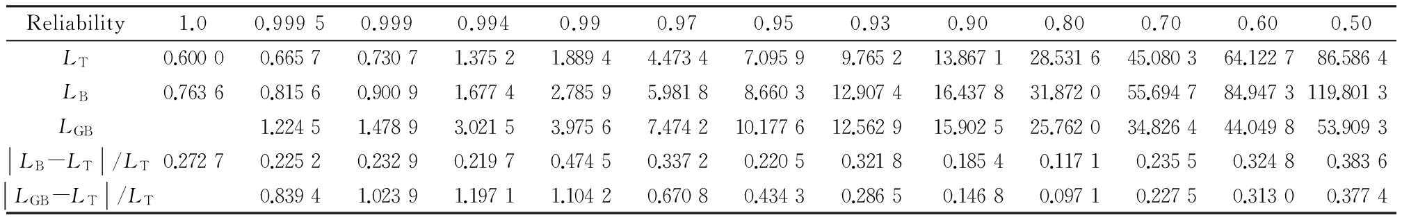
Reliability1.00.99950.9990.9940.990.970.950.930.900.800.700.600.50LT0.60000.66570.73071.37521.88944.47347.09599.765213.867128.531645.080364.122786.5864LB0.76360.81560.90091.67742.78595.98188.660312.907416.437831.872055.694784.9473119.8013LGB1.22451.47893.02153.97567.474210.177612.562915.902525.762034.826444.049853.9093LB-LT/LT0.27270.22520.23290.21970.47450.33720.22050.32180.18540.11710.23550.32480.3836LGB-LT/LT0.83941.02391.19711.10420.67080.43430.28650.14680.09710.22750.31300.3774
Tab.6 Verification of the proposed method for bearing 6307

Reliability1.00.99950.9990.9940.990.970.950.930.900.800.700.600.50LT1.85002.72683.26686.75488.844616.917223.461329.327637.416461.635684.5617107.9054132.8500LB2.25763.20453.95848.550910.575521.078828.228638.371150.031680.4434110.2853138.7987175.1361LGB3.58924.33508.856411.653121.907829.831936.823846.612475.5121102.0812129.1164158.0161LB-LT/LT0.22030.17520.21170.26590.19570.24600.20320.26080.25210.23380.23320.22260.2414LGB-LT/LT0.31630.32700.31110.31750.29500.27150.25560.24580.22510.20270.19660.1894
For the measured data in Tab.4, the fatigue life and its relative error are calculated by three different methods. From Tab.5 and Tab.6, the relative error of the proposed method is lower than that of the international standard method and its results are much closer to the actual fatigue life when reliability R>0.93. However, the relative error of the proposed method is higher than that of the international standard method when reliability R<0.8. Therefore, the 3-parameter Weibull model is more suitable for high reliability while the two-parameter Weibull model is more suitable for low reliability. On the whole, the fatigue life calculation results of the proposed method are superior to those of the current international standard ISO281: 2007 because the latter method adopts a two-parameter distribution. A large number of practices have shown that contact fatigue life is not completely consistent with two-parameter Weibull distribution, but more in line with 3-parameter Weibull distribution. In addition, the international standard ISO281: 2007 of rolling bearing fatigue life does not take into account the failure of rolling elements. Actually, rolling elements may also fail to work. Furthermore, the fatigue strength of material plays a decisive role in the life of bearings. The current international standard method does not directly introduce it but indirectly implies it in certain parameters. Once bearing material changes, great difficulties will be brought to the prediction of fatigue life for rolling bearings. The proposed method also has some defects, such as calculation difficulty, a large amount of calculation, and inconvenience for use, but these problems can be overcome by the program.
1) Through the analysis of contact stress under EHL, transformation of stress and revision of the P-S-N curve, a fatigue life prediction method of rolling bearing is proposed based on 3-parameter Weibull distribution and material fatigue strength.
2) The latest international standard ISO281: 2007 concerning the fatigue life prediction of the rolling bearing is still based on two-parameter Weibull distribution without considering the failure of rolling elements and material fatigue strength. The prediction results of fatigue life using the proposed method are closer to actual life when reliability R>0.93.
3) Compared with the international standard ISO281: 2007, the relative error of the proposed method is higher when reliability R<0.8, but that of the two methods is smaller when reliability R>0.93. Therefore, the international standard method has some limitations in part regarding high reliability.
4) Since fatigue strength is considered in this study, when the material of the bearing changes, the fatigue life calculation of the proposed method is more convenient and practical than that of the international standard method.
[1]Zhu D X, Liu H Z. Reliability evaluation of high-speed train bearing with minimum samples [J]. Journal of Central South University (Science and Technology), 2015, 44(3): 963-969. (in Chinese)
[2]Zhu L L, Lin S M, Ji X M. Research and analysis of development of life calculation method for rolling bearing[J]. Journal of Harbin Bearing, 2014,35(3): 3-6. (in Chinese)
[3]Lundberg G, Palmgren A. Dynamic capacity of rolling bearings[J/OL]. Acta Polytech Mech Eng, 1947. https://www.researchgate.net/publication/284116608_Dynamic_capacity_of_rolling_bearings.
[4]Ioannides E, Harris T A. A new fatigue life model for rolling bearing[J]. ASME Journal of Tribology, 1985, 107: 367-378. DOI:10.1115/1.3261082.
[5]Tallian T E. A data-fitted rolling bearing life prediction model—Part Ⅲ: Parametric study, comparison to published models and engineering review[J]. Tribology Transactions, 1996, 39(2): 269-275. DOI:10.1080/10402009608983528.
[6]Liu J Y, Tallian T E, McCool J I. Dependence of bearing fatigue life on film thickness to surface roughness ratio [J]. Tribology Transactions, 1975, 18(2): 144-152. DOI: 10.1080/05698197508982757.
[7]Zhang Y Q, Tan Q C, Li J G, et al. Fatigur life of raper roller bearings in drive rear axle main gear reducer [J]. Advanced Materials Research, 2012, 510(7): 112-116. DOI: 10.4028/www.scientific.net/AMR.510. 112.
[8]Potocnik R, Goncz P, Flasker J, et al. Fatigue life of double row slewing ball bearing with irregular geometry [J]. Procedia Engineering, 2010, 2(1): 1877-1886. DOI: 10.1016/j.proeng.2010.03. 202.
[9]Yu W, Harris T A. A new stress-based fatigue life model for ball bearings[J]. Tribology Transactions, 2001, 44(1): 11-18. DOI: 10.1080/10402000108982420.
[10]Yin F L, Wang Y S, Zhang C H, et al. An improved parameter estimation method for three-parameter Weibull distribution in the life analysis of rolling bearing [J]. Advanced Materials Research, 2012, 569:442-446. DOI: 10.4028/www.scientific.net/AMR.569.442.
[11]Feng Y, Huang X D, Chen J, et al. Residual life prediction of large-size slewing bearings based on small-sample test [J]. Journal of Central South University (Science and Technology), 2015, 46(9): 3252-3259. (in Chinese)
[12]Shigeo S. A new life theory for rolling bearings — by linkage between rolling contact fatigue and structural fatigue [J]. Tribology Transactions, 2012, 55(5): 558-570. DOI: org/10.1080/10402004.201281342.
[13]Shimizu S, Tsuchiya K, Tosha K. Probabilistic stress-life (P-S-N) study on bearing steel using alternating torsion life test [J]. Tribology Transactions, 2009, 52(6): 807-816. DOI: 10.1080/10402000903125345.
[14]Zhang J J, Wang Q C. Study on reliability model of automobile wheel hun-bearing [J]. Mechanical & Electrical Engineering Magazine, 2009, 26(9): 94-96. (in Chinese)
[15]Zhao S B. Anti-fatigue design[M]. Beijing: China Machine Press, 1994: 64-72. (in Chinese)
[16]Sun Z L, Chen L Y. Reliability theory and method in practical mechanism[M]. Beiijng: Science Press, 2003:89-93. (in Chinese)
[17]Richart F E, Newmark N M. A hypothesis for the determination of cumulative damage in fatigue [J]. Australian Family Physician, 2015, 41(7):523-527.
[18]Zhao G X, Li D H. Weibull distribution and computer processing of experiment data for rolling bearing[J]. Mechanical Development, 1998(2): 52-55. (in Chinese)
References:
摘要:为了更加有效地预测滚动轴承接触疲劳寿命,提出一种融合弹流润滑、材料疲劳强度和三参数Weibull分布的滚动轴承接触疲劳寿命预测方法.首先,通过将油膜压力映射到赫兹接触区域来获得椭圆接触弹流润滑下的接触应力.然后,根据串联可靠性理论推导出基于三参数Weibull分布的滚动轴承基本强度模型.考虑到应力类型、形状变化及载荷波动的影响,分别建立轴承零件关于最小寿命和特征寿命的P-S-N曲线数学模型,从而进一步推导出基于三参数Weibull分布和疲劳强度的滚动轴承疲劳寿命预测模型.最后,将采用所提方法与ISO281: 2007方法和统计学方法得到的滚动轴承疲劳寿命进行对比分析.结果表明:该方法是一种有效、可行的疲劳寿命预测方法,当可靠性R大于0.93时,其接触疲劳寿命相对误差比ISO281: 2007方法更小.
关键词:滚动轴承;三参数Weibull分布;弹流润滑;疲劳强度;接触疲劳寿命
中图分类号:TH133.33
Foundation item:The National Defense Advance Research Program (No. 81302XXX).
Citation::Lu Chunyu, Liu Shaojun. A fatigue life prediction method of rolling bearing under elliptical contact elastohydrodynamic lubrication[J].Journal of Southeast University (English Edition),2017,33(1):46-52.
DOI:10.3969/j.issn.1003-7985.2017.01.008.
DOI:10.3969/j.issn.1003-7985.2017.01.008
Received 2016-07-03.
Biographies:Lu Chunyu (1980—), male, graduate; Liu Shaojun (corresponding author), male, doctor, professor, liushaojun@csu.edu.cn.