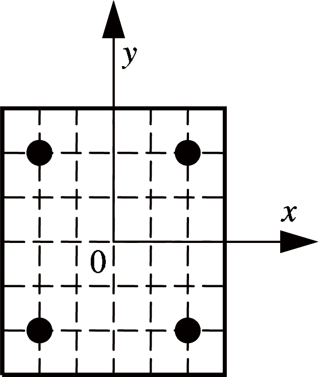
Fig.1 Fiber division of a cross-section of the column
Abstract:To improve the seismic performance of columns, engineered cementitious composite (ECC) is introduced to partially substitute concrete at the base of the columns to form ECC/reinforced concrete (RC) composite columns. The mechanical behaviors of the ECC/RC composite columns are numerically studied under low-cyclic loading with the finite element analysis software of MSC.MARC. It is found that the ECC/RC composite columns can significantly enhance the load capacity, the ductility and energy dissipation of columns. Then, the effects of the height of the ECC, the axial compression ratio and the longitudinal reinforcement ratio on the seismic behaviors of the composite columns are parametrically studied. The results show that the ECC/RC composite column with a height of the ECC layer of 0.8h(h is the height to the cross-section) can achieve similar seismic performance of a full ECC column. The peak load of the composite column increases significantly while the ductility decreases with the increase of the axial compression ratio. Increasing the longitudinal reinforcement ratio within a certain range can improve the ductility and energy dissipation capacity and almost has no effect on load capacity. The analysis results are instructive and valuable for reference in designing ECC structures.
Key words:engineered cementitious composites (ECC); ECC/RC composite columns; hysteretic curves; ductility; energy dissipation; parametric analysis
It is well known that some severe earthquakes occurred in our country and caused tremendous economic and life loss. According to previous investigation on structural earthquake damage, the plastic hinge failure at the end of the column is a typical failure mode in frame structures due to the brittleness and deficiency in deformability of concrete[1]. The design concept “strong column and weak beam” is difficult to achieve in reality. To avoid this kind of failure mode and improve the seismic performance of the frame structure, increasing longitudinal or transverse reinforcement of the columns is often used. However, the ductility and seismic performance of the structure cannot be effectively improved by this method. The reason is that increasing additional longitudinal reinforcement may cause over-reinforced concrete failures and the inherent brittleness and deficiency in deformability of concrete remain still unchanged[2]. In addition, the deficiency of the bond between the reinforcing steel bars and the surrounding concrete remains a problem for conventional reinforced concrete.
To satisfy the requirements of both loading capability and ductility of the frame structure under seismic action, replacing concrete with engineered cementitious composite (ECC) is an effective and economical alternative. ECC is a class of high performance fiber reinforced composites designed based on micromechanics, and it has been developed for application in the construction industry during recent decades[3-4]. Previous experimental research shows that the ECC material has similar ranges of tensile (4 to 6 MPa) and compressive strengths (30 to 80 MPa) compared with conventional concrete, but it distinctly differs in tensile deformation behaviors. For an ECC plate subjected to uniaxial tension, the tensile load capacity continues to increase with strain-hardening behavior after the first crack, accompanied by multiple fine cracks along the plate, while the concrete fails in a brittle manner once reaching its tensile strength[5]. ECC designed properly has good ductility with an ultimate tensile strain of over 3%, nearly 300 times that of concrete. The ECC material has super-high toughness and energy absorption ability compared with normal concrete [6]. Studies indicate that using ECC materials in engineering structures can significantly improve the bearing capacity, ductility and energy dissipation of the structures[7-9]. Moreover, super high deformability of ECC can also contribute to the bond strength between ECC and steel reinforcement[10]. Considering the high cost of ECC compared with concrete, fully replacing concrete with ECC is not realistic or economical. Therefore, partly substituting concrete with ECC at the critical parts of important elements in concrete structures is economically and technically feasible.
In order to evaluate the seismic performance of the ECC/RC composites columns of the frame structure, experimental and theoretical investigation on the behavior of the columns subjected to reversed cyclic loading have been conducted in our group. In this paper, based on the previous studies on material properties, numerical simulation of ECC/RC composites columns and RC columns under reversed cyclic loading were conducted with the finite element analysis (FEA) software MSC.MARC. The effects of the height of the ECC layer, the axial compression ratio and the longitudinal reinforcement ratio on the seismic performance of the composite columns are studied.
1.1 Fiber model
A fiber model program named THUFIBER developed by MSC.MARC is employed to build the numerical model of the ECC/RC composite and RC columns. For the fiber model, a cross-section is divided into a number of fibers and each of the fibers is subjected to uniaxial stress. The uniaxial stress-strain relationship is used to describe the characteristics of the fiber element, and the plane remaining plane is assumed for deformation compatibility between the fibers in the same cross section[11]. The hysteretic constitutive model of ECC material is added to simulate the mechanical behavior of ECC/RC composite columns under reversed cyclic loading.
Based on the actual layout of each material in the specimen, the sections of columns are divided into 36 fibers and 4 reinforcement fibers in the THUFIBER program, as shown in Fig.1. The displacement increment method is used to calculate and analyze the composite column in a complex stress state. Strict force and displacement convergence criteria are adopted in this process and the convergence tolerance is 0.5%.
Fig.1 Fiber division of a cross-section of the column
1.2 Constitutive model of steel reinforcement
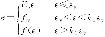
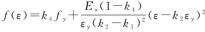
The uniaxial constitutive model of the steel reinforcement is shown in Fig.2. The Esmaeily & Xiao model[12] is used for the case of monotonic loading, and the Légeron model[13] is applied for the cases of unloading and reloading curves, as shown in Fig.3. The model in the subsequent reloading path takes Bauschinger effect into account, which can reflect material hysteresis and stiffness degradation under cyclic loading. The expression of the constitutive model of steel reinforcement is given as
(1)
(2)
where σ, ε and Es are the stress, strain and elastic modulus of steel bar, respectively; fy and εy are the yield stress and yield strain; k1, k2 and k3 are the ratios of the strain hardening starting point, peak strain, ultimate strain to the yield strain; k4 is the ratio of peak stress to yield stress fy.
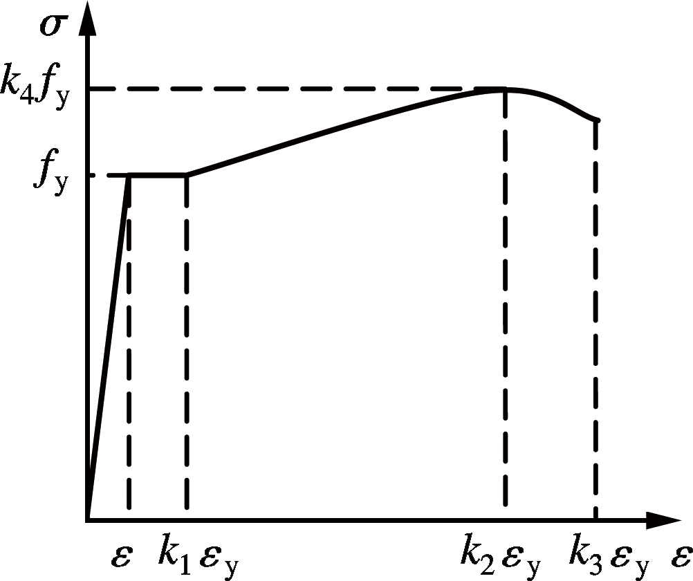
Fig.2 Uniaxial constitutive model of reinforcement
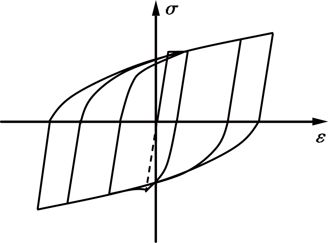
Fig.3 Hysteretic constitutive model of reinforcement
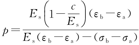
In the unloading and reloading curve, the unloading path is a straight line and the expression of reloading reversely is given as
σ=[Es(ε-εa)+σa]- ![]()
(3)
(4)
where c defines the slope of equivalent hardening line, which is obtained by connecting the yield point and the peak point; εa and σa are the strain and stress of intersection of each hysteretic loop and horizontal axis; εb and σb are the peak strain and stress of the hysteretic loop.
When there is no complete test data for the steel reinforcement, it is recommended to take the value as k1=4 (k1=1 to 2 for hard steel or strand), k2=25 (k2=10 for hard steel or strand), k3=40 and k4=1.2[14]. Combined with the test parameters of the steel reinforcement (see Tab.1) conducted in our group, the parameters of the model for steel reinforcement is listed in Tab.2.
Tab.1 Test parameters of steel reinforcement
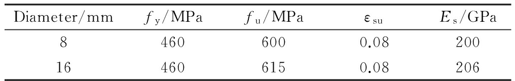
Diameter/mmfy/MPafu/MPaεsuEs/GPa84606000.08200164606150.08206
Tab.2 Parameters of the model for steel reinforcement
fy/MPaεyEs/GPak1k2k3k44600.0023200425351.3
1.3 Constitutive model of concrete
A simplified constitutive model (see Fig.4) is used for concrete. In the figure, σ and ε are the stress and strain of concrete, respectively; σu and εu are the concrete ultimate compressive stress and the corresponding compressive strain; fc and ε0 are the peak compressive stress and peak compressive strain; ft and εt0 are the peak tensile strength of concrete and peak tensile strain.

Fig.4 Hysteretic constitutive model of concrete
The curve in the compression zone is divided into two stages: the ascending part and the descending part. The descending part is a straight line. The ascending part is given by
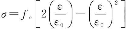
(5)
The unloading part is a linear function to the origin. The curve in tension is classified into two stages, and both ascending and descending parts are assumed to be straight lines. The unloading or reloading curve remains a linear function to the origin. By modifying the concrete ultimate compressive stress σu and the corresponding compressive strain εu, the behavior of normal concrete and constrained concrete can be simulated. The typical parameters of the constitutive model of concrete are listed in Tab.3.
Tab.3 Parameters of model of constitutive model of concrete
fc/MPaε0σu/MPaεuft/MPaEc/MPaεt0εtu300.00225.50.0042.5133.50.000150.0012
1.4 Constitutive model of ECC
Currently, little research on the hysteretic constitutive relationship of the ECC material under cyclic loading has been conducted. The simplified ECC material tension and compression constitutive relationship proposed by Han et al.[15-16] is used for calculation and analysis. The expression of the model is given as
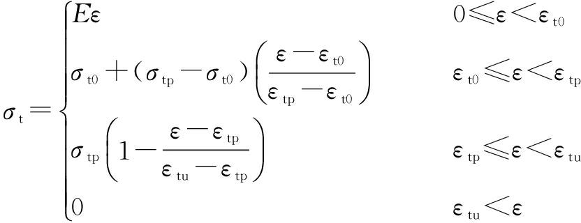
(6)
where E is Young’s modulus of ECC; σt0 and εt0 are the first crack tensile stress and strain, respectively; σtp and εtp are the peak tensile stress and strain, respectively; σtu and εtu are the ultimate tensile stress and strain of ECC, respectively.
(7)
where σcp is the peak compressive stress; εcp is the first crack compressive strain; εcu is the ultimate compressive strain of ECC.
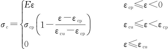
To reflect the hysteresis and stiffness degradation characteristics of ECC material under reversed cyclic loading, the path of unloading and reloading curves in tension and compression is shown in Fig.5 [15].

(a)
(b)
Fig.5 Hysteretic constitutive model of ECC. (a) In tension; (b) In compression
In Fig.5, ![]() and
and ![]() are the stress and strain of the unloading point in the skeleton curve;
are the stress and strain of the unloading point in the skeleton curve; ![]() is the residual strain when the ECC tensile stress reaches zero during unloading, and it is α times the unloading point strain.
is the residual strain when the ECC tensile stress reaches zero during unloading, and it is α times the unloading point strain. ![]() and
and ![]() are the stress and strain of a certain point in the softening part of the skeleton curve in compression;
are the stress and strain of a certain point in the softening part of the skeleton curve in compression; ![]() is the residual strain when the ECC compressive stress reaches zero during unloading, and it is β times the unloading point strain.
is the residual strain when the ECC compressive stress reaches zero during unloading, and it is β times the unloading point strain.
Based on the experimental results of ECC materials under uniaxial cyclic loading[16], the tensile and compressive stress-strain curves of ECC materials are simplified, and the constitutive models of ECC materials under cyclic loading are obtained. The main parameters of the constitutive model of ECC are tested by uniaxial tension and compression experiments, as shown in Tab.4.
Tab.4 Parameters of model of the constitutive model of ECC
σt0/MPaεt0σtp/MPaεtpσcp/MPaεcpεcuαβ2.510.000213.770.03300.0040.0120.40.3
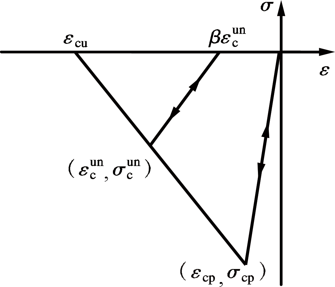
The ECC/RC composite to be simulated is shown in Fig.6. In the finite element model, the column specimens are fixed by the foundation and are subjected to horizontal and vertical loads at the top of the columns. The size of the cross-sections of columns is 250 mm×250 mm and the length of the column is 1 100 mm. The horizontal load is applied at 100 mm from the top of the column, and the shear span ratios for the columns are 4.0. The columns are reinforced with four 16-mm-diameter bars symmetrically, and they are designed with proper stirrups with the diameter of 8 mm and the spacing of 150 mm in the shear span.
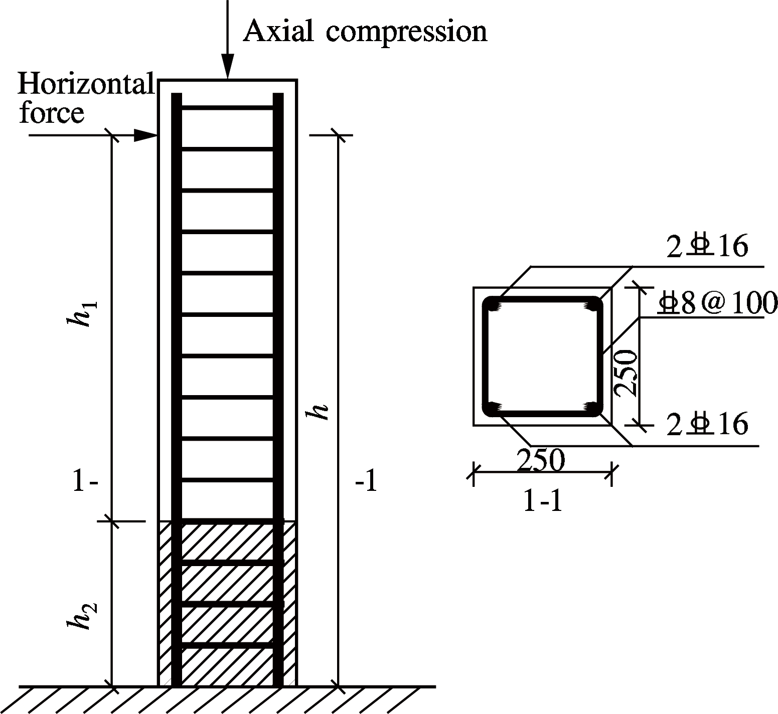
Fig.6 Finite element model of the ECC/RC composite column
Previous studies have shown that when subjected to horizontal and vertical loads, a long part of the column from the loading point is in a low stress state and the material properties are not fully utilized[17]. The main failure area is concentrated within the plastic hinge zone which is h1 from the bottom of the foundation. If the plastic zone of concrete is replaced with ECC, the seismic performance of the column can be greatly improved. Since a previous study showed that ECC can deform compatibly with steel reinforcement[18], perfect bond between ECC and steel reinforcement is assumed in the numerical analysis. For the RC column, the layout of the reinforcement is the same as that of the ECC/RC composite column, and the matrix of the column is normal concrete. The columns are loaded with displacement control during the loading process.
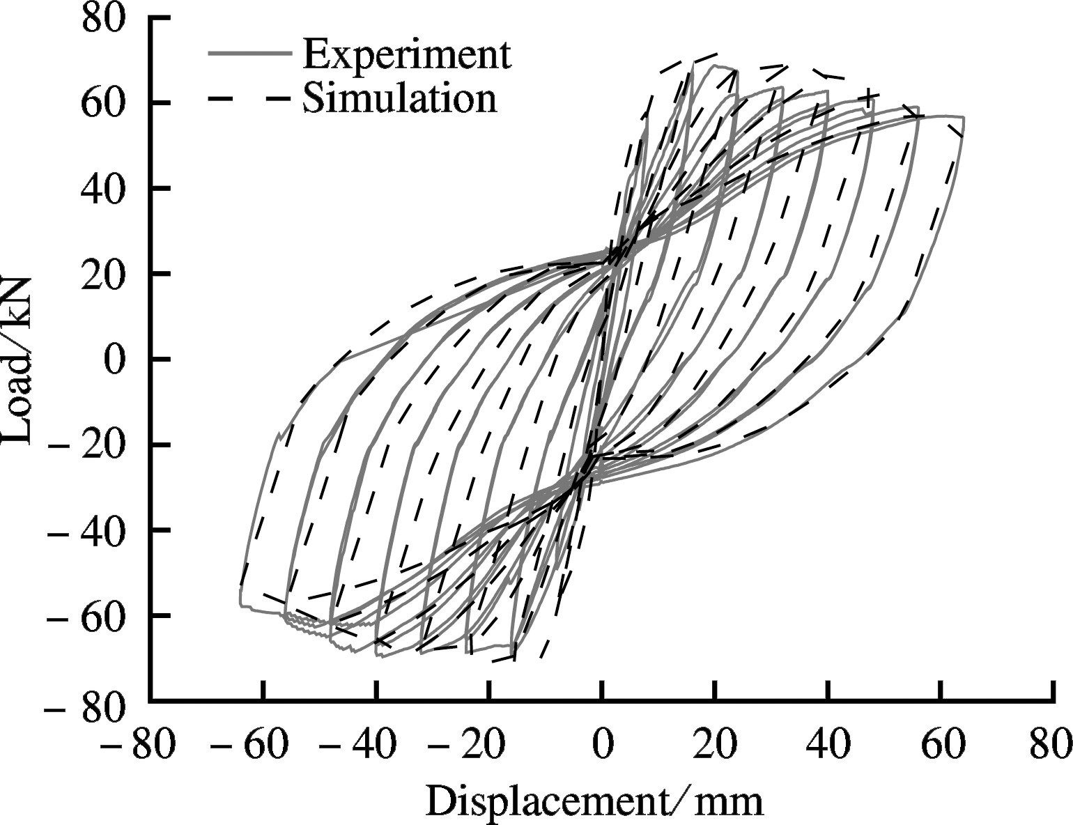
Yuan[19] carried out numerical simulation of the hysteretic behavior of ECC/RC composite beam members under cyclic loading using the THUFIBER program. The simulation results match well with test results and it suggests that the analytical method can accurately reflect the hysteretic characteristics of ECC/RC composite members under cyclic loading. Experimental study on the mechanical behavior of ECC/RC composite columns under cyclic loading has been conducted in our group. To further demonstrate the validity of the finite element model, a comparison between the simulation results and experimental results is carried out. The comparison of simulation and experiment results of the ECC/RC composite column are shown in Fig.7.
(a)

(b)
Fig.7 Comparison of simulation and experiment results.(a) Hysteretic curves; (b) Envelope curves
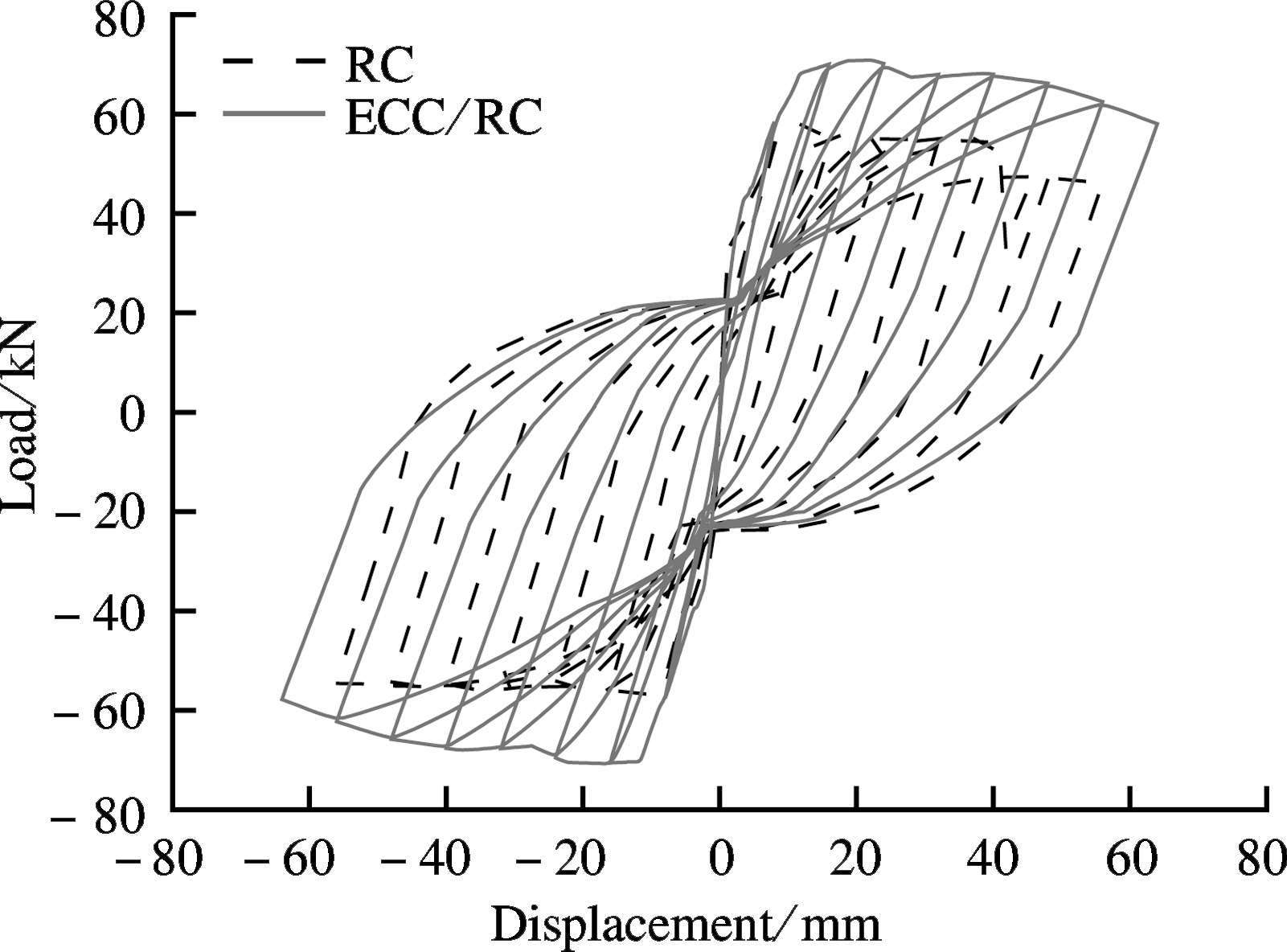
Fig.7 shows that the simulation hysteretic curves and the envelope curves are in good agreement with the experimental results. Hence, the fiber model and the constitutive models of reinforcement, concrete and ECC materials used in the simulation are effective for numerical analysis. Based on the same simulation method, the mechanical behaviors of the RC column under cyclic loading are numerically analyzed and compared with those of the ECC/RC column (see Fig.8). In this part, the height of the ECC layer is 1.2h (h is the height of the cross-section of the column).
(a)

(b)
Fig.8 Calculation results of RC and ECC column. (a) Hysteretic curves; (b) Envelope curves
From the hysteretic curves, the process of destruction of the column can be divided into three steps: 1) In the first several stages of loading, the column is in elastic state. 2) After yielding, the curve deviates from the original straight line and the slope starts to decrease. Load increases gradually until reaching peak load. 3) After peak load, the load decreases slowly with the increase of displacement, showing good deformability of the column. The final failure load is approximately 85% of the peak load and failure mode exhibits bending failure. The residual deformation (intercept of the curve with the displacement axis) of both the RC column and the ECC/RC column is small and hysteretic curves are closer to the origin at first. Then, the residual deformation increases with the
increasing times of unloading, indicating that the concrete or the ECC is being gradually damaged. For each hysteretic loop after yielding, the slope of the unloading curve reduces at an increasing rate, suggesting that stiffness reduces increasingly under reversed cyclic loading.
Overall, the hysteretic curves of the columns are in full spindle shape, indicating that the columns have a strong energy dissipation capacity. As can be seen from the comparison of the hysteretic curves, the hysteretic curves of the RC column is included in those of the ECC/RC column, showing that the seismic performance of the ECC/RC column is significantly greater than that of the RC column. Fig.9 plots the accumulative energy dissipation of the RC and ECC/RC columns, which is the sum of the area that every hysteretic loop contains. According to the calculation results, the cumulative energy dissipation of the ECC column is 1.32 times that of the RC column.
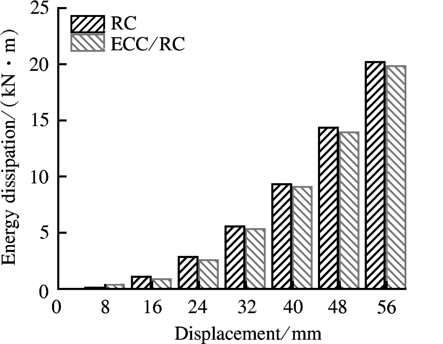
Fig.9 Energy dissipation of RC and ECC/RC column
The envelope curve is the curve of connecting peak point of every hysteretic loop. As can be seen from Fig.8(b), the peak load of the ECC/RC is significantly greater than that of the RC column. The deformation resilience ability of the structure is very important for earthquake resistance and recovery work after the earthquake. To evaluate the deformation resilience ability, the displacement ductility coefficient μ is defined as
μ=Δu/Δy
(8)
where Δu and Δy are the ultimate displacement and yield displacement, respectively. The calculation results are shown in Tab.5.
Tab.5 Summary of calculation results of specimens RC and ECC/RC
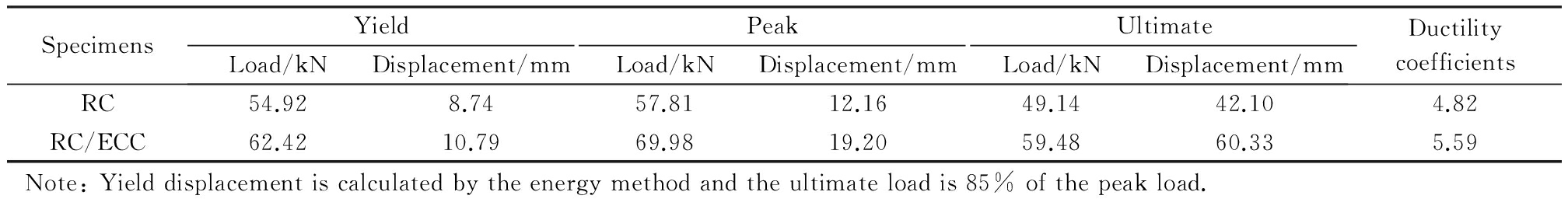
SpecimensYieldPeakUltimateLoad/kNDisplacement/mmLoad/kNDisplacement/mmLoad/kNDisplacement/mmDuctilitycoefficientsRC54.928.7457.8112.1649.1442.104.82RC/ECC62.4210.7969.9819.2059.4860.335.59Note:Yielddisplacementiscalculatedbytheenergymethodandtheultimateloadis85%ofthepeakload.
The peak load and ultimate displacement of the ECC column is higher than those of the RC column, which means that ECC/RC composite columns have higher load capacity and deformation capacity under earthquake action. Compared with the RC column, the peak load of the ECC/RC column increases by 21.05% while the ultimate displacement increases by 42.10 to 60.33 mm. The displacement ductility coefficient of the ECC column is much higher than that of the RC column, approximately 1.16 times of the RC column.
Considering the performance price ratio of the columns and full use of ECC material, it is necessary to investigate the effect of the height of ECC on the seismic performance of the composite columns. The axial compression ratio and longitudinal reinforcement ratio are another two important factors determining the seismic performance of columns. In this section, the effects of different parameters, including the height of the ECC layer, axial compression ratio, and longitudinal reinforcement ratio, on the seismic behaviors of columns are comprehensively studied.
Tab.6 lists the description of the specimens in terms of shear span ratio, height of the ECC layer, axial compression ratio and longitudinal reinforcement ratio.
Tab.6 Detailed configuration of columns

SpecimensShearspanratiohEAxialcompressionratioρ/%RC-04.000.301.3ECC-04.0l0.301.3E/R-14.00.4h0.301.3E/R-24.00.8h0.301.3E/R-34.01.2h0.301.3E/R-44.00.8h0.301.3E/R-54.00.8h0.451.3E/R-64.00.8h0.601.3E/R-74.00.8h0.300.7E/R-84.00.8h0.301.3E/R-94.00.8h0.302.0Notes:histhesizeofthecross-sectionofthecolumn;listheheightofthecolumn;hEistheheightoftheECClayer;andρisthelongitudinalreinforcementratioofthecolumn.
4.1 Effect of the height of ECC layer
In this part, five specimens with different heights of ECC layer are numerically studied, and the calculation results are listed in Tab.7.
It can be found that the yield displacements of E/R-1, 2, 3 and ECC-0 are larger than that of RC-0 because the elastic modulus of ECC is smaller than that of normal concrete. However, the peak loads show the opposite trend because the tensile strength of ECC can make contributions to the moment capacity while the tensile strength of concrete is generally not taken into account. Further analysis found that this phenomenon is becoming increasingly evident with the ECC layer thickness increasing from E/R-1 to ECC-0, reflecting the superiority of the ECC material properties. The peak load and ductility of columns improve with the increase in the height of the ECC layer. According to Tab.6, the yield load, peak load and ductility coefficients of E/R-2 are 0.969, 0.975 and 0.955 times those of the whole ECC column, respectively.
Figs.10 and 11 plot the results of envelope curves and accumulative energy dissipation of columns with different heights of the ECC layer. The envelope curves of specimen RC-0 and E/R-1 are similar and the energy dissipations are both approximately 20.2 kN·m. When the height of the ECC layer increases to 0.8h, the peak load improves to a large degree and the energy dissipation of specimen E/R-2 increases to 24.93 kN·m, which is 1.23 times that of specimen RC-0. The ultimate displacement and accumulative energy dissipation of E/R-2 are similar to those of specimen ECC-0. It can be concluded that when the height of the ECC layer reaches 0.8h, the mechanical behavior of the ECC/RC composite column is similar to that of the full ECC column with the same size and steel details. The reason lies in that the length of the column plastic hinge is approximately 0.8h, and replacing concrete with ECC within the plastic hinge zone is the most effective way to increase the seismic behavior of the column.
Tab.7 Summary of calculation results of specimens with different ECC heights
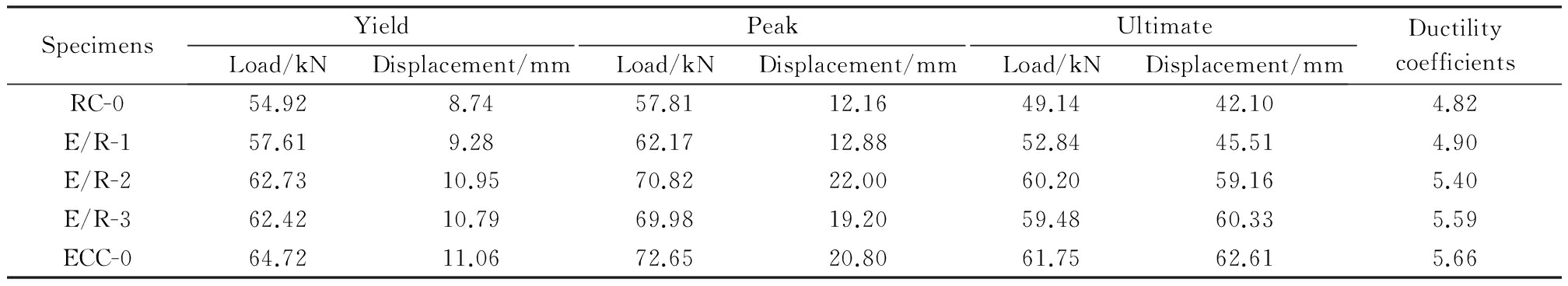
SpecimensYieldPeakUltimateLoad/kNDisplacement/mmLoad/kNDisplacement/mmLoad/kNDisplacement/mmDuctilitycoefficientsRC-054.928.7457.8112.1649.1442.104.82E/R-157.619.2862.1712.8852.8445.514.90E/R-262.7310.9570.8222.0060.2059.165.40E/R-362.4210.7969.9819.2059.4860.335.59ECC-064.7211.0672.6520.8061.7562.615.66

Fig.10 Envelope curves of columns
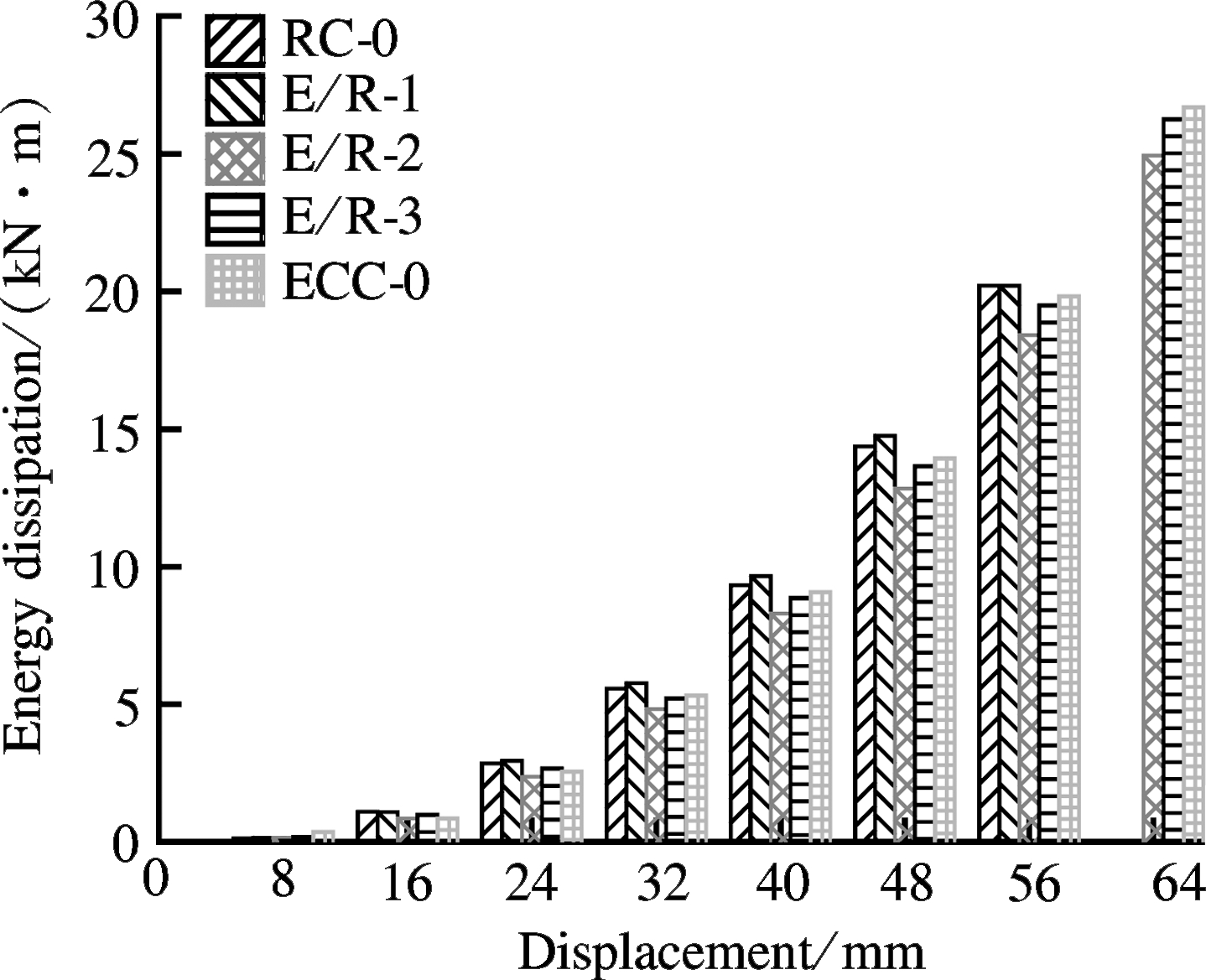
Fig.11 Energy dissipation of columns
4.2 Effect of the axial compression ratio
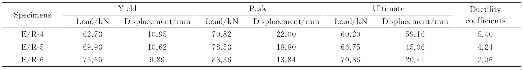
Existing literature suggests that the axial compression ratio has a great effect on the seismic behaviors of frame columns. Three specimens with different axial compression ratios are numerically studied. The calculation results are listed in Tab.8 and the envelope curves and accumulative energy dissipation are shown in Figs.12 and 13.
It can be concluded from Fig.12 that the peak load of the composite column increases significantly while the ductility decreases with the increase of the axial compression ratio. Compared with specimen E/R-4, the peak loads of E/R-5 and E/R-6 increase by 10.89% and 17.71%, while the ultimate displacements decrease by 23.83% and 65.51%, respectively. This indicates that the percentage of reduction in ultimate displacement is greater than the increase of peak load with the increase of axial compression ratio. When the displacement reaches 56 and 64 mm, E/R-6 and E/R-5 reaches final failure successively. The energy dissipation of E/R-5 and E/R-6 decreases by 24.20% and 43.00% compared with E/R-4. In addition, the descending stage of the envelope curve becomes steeper and stiffness reduces at an increasing rate with the increase of the axial compression ratio.
Tab.8 Summary of calculation results of E/R-4, E/R-5 and E/R-6
SpecimensYieldPeakUltimateLoad/kNDisplacement/mmLoad/kNDisplacement/mmLoad/kNDisplacement/mmDuctilitycoefficientsE/R-462.7310.9570.8222.0060.2059.165.40E/R-569.9310.6278.5318.8066.7545.064.24E/R-675.659.8983.3613.8470.8620.412.06

Fig.12 Envelope curves of E/R-4 to E/R-6
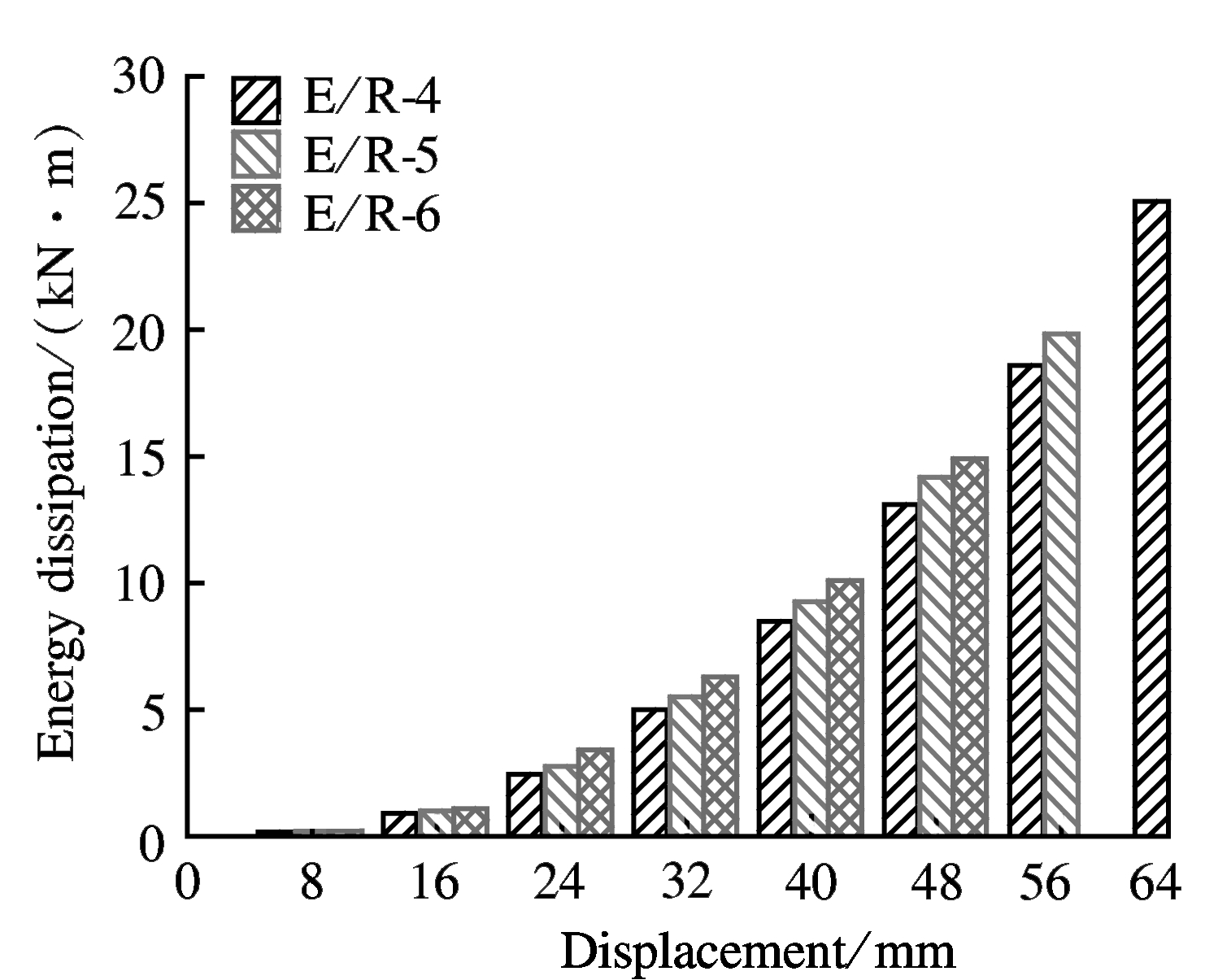
Fig.13 Energy dissipation of E/R-4 to E/R-6
4.3 Effect of the longitudinal reinforcement ratio
To avoid the brittle failure of reinforced concrete columns, the longitudinal reinforcement ratio of the column is limited within a certain range. In this part, three specimens with different longitudinal reinforcement ratios are chosen for analysis. Calculation results are shown in Tab.9.
The yield load and peak load of specimens E/R-7 and E/R-8 are very close, but the ductility of E/R-8 is superior to E/R-7. The longitudinal reinforcement ratio of specimen E/R-7 is 0.7%, which is slightly greater than the minimum longitudinal reinforcement ratio[20]. The failure mode of E/R-7 is similar to the under-reinforced beam and this is the reason why the deformation ability and the ductility of specimen E/R-7 are at a very low level. Compared with the E/R-8, the peak load of E/R-9 only increases by 5.06% but the ductility coefficient increases by 9.75% as the reinforcement ratio increases from 1.3 to 2.0. These figures indicate that the deformability and ductility can increase greatly while the load capacity is improved by a very small degree by increasing the longitudinal reinforcement ratio. Figs.14 and 15 plot the envelope curves and accumulative energy dissipation of specimen E/R-7 to E/R-9.
Fig.14 shows that the ultimate displacement of the composite columns increases greatly while the peak load almost remains unchanged with the increase of the longitudinal reinforcement ratio, indicating that increasing the longitudinal reinforcement ratio can effectively improve the ductility of columns under cyclic loading. When the displacement increases to 56 mm, specimen E/R-7 reaches final failure, showing a certain degree of brittle failure characteristics due to a small longitudinal reinforcement ratio. The energy dissipation of E/R-7, E/R-8 and E/R-9 are similar before reaching 48 mm. However, the energy dissipation of E/R-8 and E/R-9 are much higher than that of E/R-7 after the displacement reaches 56 mm. When the displacement reaches 64 mm, the energy dissipation of E/R-9 is greater than that of E/R-8, indicating that the ductility and energy dissipation of ECC/RC composite columns under cyclic loading increase significantly with the increase of the longitudinal reinforcement ratio.
Tab.9 Summary of calculation results of E/R-7, E/R-8 and E/R-9
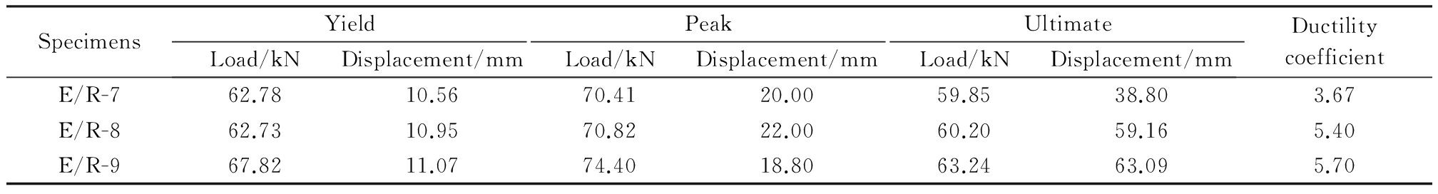
SpecimensYieldPeakUltimateLoad/kNDisplacement/mmLoad/kNDisplacement/mmLoad/kNDisplacement/mmDuctilitycoefficientE/R-762.7810.5670.4120.0059.8538.803.67E/R-862.7310.9570.8222.0060.2059.165.40E/R-967.8211.0774.4018.8063.2463.095.70

Fig.14 Envelope curves of E/R-7 to E/R-9
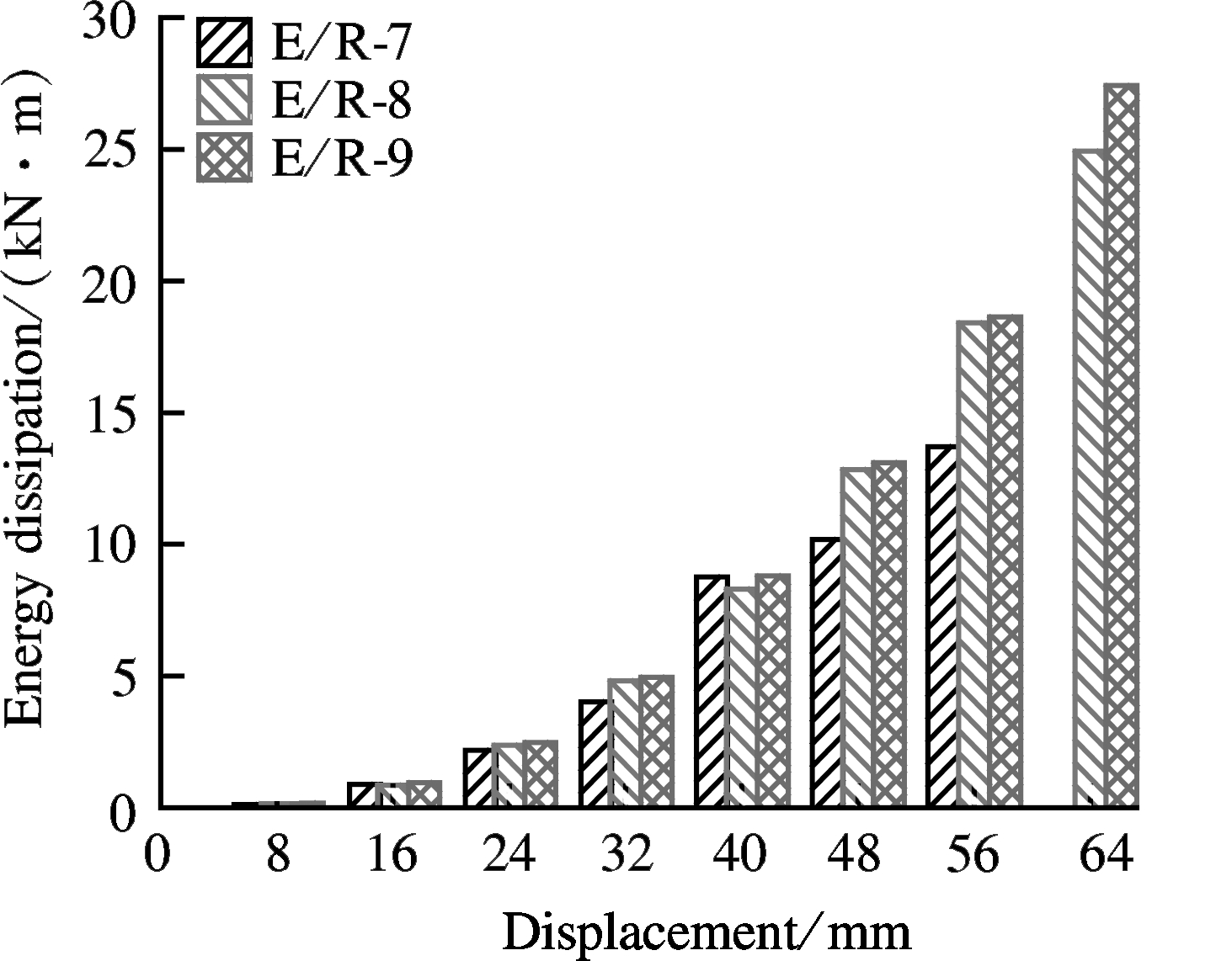
Fig.15 Energy dissipation of E/R-7 to E/R-9
1) Replacing concrete with ECC at the base of the column can obviously enhance the seismic performance of the columns.
2) The ECC layer at the base can improve the peak load, ultimate displacement and energy dissipation of the composite columns. The ECC/RC composite column with an ECC height of 0.8h can almost achieve a similar seismic performance to a full ECC column.
3) With the increase of the axial compression ratio, the load capacity improves significantly while the ultimate displacement decreases. The energy dissipation, ultimate displacement and stiffness decrease at an increasing rate.
4) Increasing the longitudinal reinforcement ratio within a certain range can improve the ductility and energy dissipation capacity and has almost no effect on load capacity.
[1]Tsai M H, Lin B H. Investigation of progressive collapse resistance and inelastic response for an earthquake-resistant RC building subjected to column failure [J]. Engineering Structures, 2008, 30(12): 3619-3628. DOI:10.1016/j.engstruct.2008.05.031.
[2]Ye L P, Qu Z, Ma Q L, et al. Study on ensuring the strong column-weak beam mechanism for RC frames based on the damage analysis in the Wenchuan earthquake [J]. Building Structure, 2008(11): 52-59,67.
[3]Kim Y Y, Fischer G, Li V C. Performance of bridge deck link slabs designed with ductile ECC [J]. ACI Structural Journal, 2004, 101(6):792-801.
[4]Lepech M D, Li V C. Application of ECC for bridge deck link slabs [J]. Materials and Structures, 2009, 42(9):1185-1195. DOI:10.1617/s11527-009-9544-5.
[5]Li V C. Engineered cementitious composites-tailored composites through micromechanical modeling [C]//Fiber Reinforced Concrete: Present and Future. Montreal: Canadian Society for Civil Engineering, 1998: 64-97.
[6]Christopher K Y L, Cheung Y N, Zhang J. Fatigue enhancement of concrete beam with ECC layer [J]. Cement and Concrete Research, 2007, 29(6):465-473.
[7]Park W S, Yun H D. Seismic performance of pseudo strain-hardening cementitious composite coupling beams with different reinforcement details [J]. Composites Part B: Engineering, 2011, 42(6):1427-1445. DOI:10.1016/j.compositesb.2011.04.049.
[8]Parra-Montesinos G, Wight J K. Seismic response of exterior RC column-to-steel beam connections [J]. Journal of Structural Engineering, 2000, 126(10):1113-1121. DOI:10.1061/(asce)0733-9445(2000)126:10(1113).
[9]Fukuyama H. Application of high performance fiber reinforced cementitious composites for damage mitigation of building structures [J]. Advance Concrete Technology, 2006, 4(1):35-44. DOI:10.3151/jact.4.35.
[10]Li V C. On engineered cementitious composites (ECC)[J]. Journal of Advanced Concrete Technology, 2003, 1(3): 215-230. DOI:10.3151/jact.1.215.
[11]Wang X L, Lu X Z, Ye L P. Numerical simulation for the hysteresis behavior of RC columns under cyclic loads [J]. Engineering Mechanics, 2007,24(12):76-81.
[12]Esmaeily A, Xiao Y. Behavior of reinforced concrete columns under variable axial loads: analysis [J]. ACI Structural Journal, 2005, 102(5):736-744.
[13]Légeron F, Paultre P, Mazars J. Damage mechanics modeling of nonlinear seismic behavior of concrete structures [J]. Structural Engineering, 2005, 131(6): 946-954. DOI:10.1061/(asce)0733-9445(2005)131:6(946).
[14]Wang X L. Research on resetting performance of non-cohesive reinforced concrete columns with high strength steel strand [D]. Beijing: School of Civil Engineering, Tsinghua University, 2007. (in Chinese)
[15]Han T S, Feenstra P H, Billington S L. Simulation of highly ductile fiber-reinforced cement-based composite components under cyclic loading[J]. ACI Structural Journal, 2003, 100(6): 749-757.
[16]Kesner K E, Billington S L. Investigation of ductile cement-based composites for seismic strengthening and retrofit [C]//Proceedings of the Fourth International Conference on Fracture Mechanics of Concrete Structures. Cachan, France, 2001: 65-72.
[17]Shan Q F, Pan J L, Chen J H. Mechanical behaviors of steel reinforced ECC/concrete composite columns under combined vertical and horizontal loading [J]. Journal of Southeast University (English Edition), 2015, 31(2):259-265.
[18]Li V C, Fischer G. Interaction between steel reinforcement and engineered cementitious composites[C]//Proceedings of the Third International Workshop on High Performance Fiber Reinforced Cement Composites. Mainz, Germany,1999: 361-369.
[19]Yuan F. Seismic behaviors of steel reinforced ECC/reinforced concrete composite frame structures [D]. Nanjing: School of Civil Engineering, Southeast University, 2014. (in Chinese)
[20]Ministry of Housing and Urban-Rural Development of the People’s Republic of China. GB 50010—2010 Code for design of concrete structures [S]. Beijing: China Building Industry Press, 2010.(in Chinese)
References:
摘要:为提高柱的抗震性能,采用高延性纤维增强水泥基复合材料(ECC)部分代替钢筋混凝土柱底部的混凝土得到ECC/RC组合柱.采用MSC.MARC有限元软件分析了组合柱在低周反复荷载作用下的受力性能.分析发现采用ECC/RC组合柱能够显著提高柱的承载力、延性和耗能能力.然后探究了ECC高度、轴压比和纵筋配筋率3个参数对ECC/RC组合柱抗震性能的影响.结果表明:ECC高度在0.8h(h为截面高度)左右的组合柱近似可以达到全ECC 柱的抗震性能;随着轴压比的增加,组合柱的承载力增加,而延性下降;在适当配筋的范围内,提高配筋率可以提高组合柱的延性和耗能能力,对承载力几乎无影响.分析结果对于ECC结构设计具有一定的指导意义和参考价值.
关键词:高延性纤维增强水泥基复合材料;ECC/混凝土组合柱;滞回曲线;延性;耗能;参数分析
中图分类号:TU375.3
Foundation items:The National Natural Science Foundation of China (No.51278118), the Natural Science Foundation of Jiangsu Province (No.BK2012756), the Key Project of Ministry of Education of China (No.113029A), the Third Five-Year Major Scientific and Technological Project of China Metallurgical Group Corporation.
Citation::Pan Jinlong, Mo Chuang, Xu Li, et al. Seismic behaviors of steel reinforced ECC/RC composite columns under low-cyclic loading[J].Journal of Southeast University (English Edition),2017,33(1):70-78.
DOI:10.3969/j.issn.1003-7985.2017.01.012.
DOI:10.3969/j.issn.1003-7985.2017.01.012
Received 2016-07-18.
Biography:Pan Jinlong (1976—), male, doctor, professor, jinlongp@gmail.com.