Abstract:To solve the problem that metal artifacts severely damage the clarity of the organization structure in computed tomography (CT) images, a sinogram fusion-based metal artifact correction method is proposed. First, the metal image is segmented from the original CT image by the pre-set threshold. The original CT image and metal image are forward projected into the original projection sinogram and metal projection sinogram, respectively. The interpolation-based correction method and mean filter are used to correct the original CT image and preserve the edge of the corrected CT image, respectively. The filtered CT image is forward projected into the filtered image sinogram.According to the position of the metal sinogram in the original sinogram and filtered image sinogram, the corresponding sinograms![]() (in the original sinogram) and
(in the original sinogram) and ![]() (in the filtered image sinogram) can be acquired from the original sinogram and filtered image sinogram, respectively. Then,
(in the filtered image sinogram) can be acquired from the original sinogram and filtered image sinogram, respectively. Then, ![]() and
and ![]() are fused into the fused metal sinogram
are fused into the fused metal sinogram ![]() according to a certain proportion. The final sinogram can be acquired by fusing
according to a certain proportion. The final sinogram can be acquired by fusing ![]() ,
, ![]() and the original sinogram PO. Finally, the final sinogram is reconstructed into the corrected CT image and metal information is compensated into the corrected CT image. Experiments on clinical images demonstrate that the proposed method can effectively reduce metal artifacts. A comparison with classical metal artifacts correction methods shows that the proposed metal artifacts correction method performs better in metal artifacts suppression and tissue feature preservation.
and the original sinogram PO. Finally, the final sinogram is reconstructed into the corrected CT image and metal information is compensated into the corrected CT image. Experiments on clinical images demonstrate that the proposed method can effectively reduce metal artifacts. A comparison with classical metal artifacts correction methods shows that the proposed metal artifacts correction method performs better in metal artifacts suppression and tissue feature preservation.
Key words:metal artifacts; interpolation-based method; sinogram fusion-based; computed tomography (CT) image
Computed tomography (CT) has been widely used in practice since its invention in the 1970s. In the absence of metal, the CT imaging system can provide clear images with high-resolution anatomical information. However, some metal objects are present in the scanning field, such as dental implants, internal fixation and prosthesis et al. Some streak artifacts (metal artifacts) emerge in reconstructed CT image by using the filter back projection (FBP) algorithm with the raw projection data. The metal artifacts greatly deteriorate image quality and seriously affect the diagnostic effects. Therefore, researchers have proposed some metal artifacts correction methods to reduce these artifacts and improve image quality.
These metal artifact correction methods can be roughly grouped into the following three categories; namely the interpolation-based correction method[1-9], iterative reconstruction correction method[10-12] and hybrid correction method[13]. The interpolation-based correction method replaces the unreliable data in the corrupted metal trace with surrogate data obtained by using interpolation techniques[8]. In the interpolation-based correction techniques, the linear interpolation is the simplest and earliest interpolation algorithm[1]. Besides the linear interpolation, there is the polynomial interpolation algorithm[2], wavelet interpolation[3], normalized interpolation[4], etc. The most crucial problem for the interpolation-based correction method is the additional artifacts for the corrected images. The iterative reconstruction correction method can effectively remove the metal artifacts in the original image. However, low efficiency limits its use. The hybrid correction method[13] is the integration of the interpolation-based correction method and iterative reconstruction correction method. The integrated method possesses the advantages of the interpolation-based correction method and iterative reconstruction correction method. The fatal shortcoming of the hybrid method is the function allocation problem between the interpolation-based correction method and iterative reconstruction correction method.
To remove the metal artifacts in the CT image, in this paper, a sinogram fusion-based metal artifact correction method is introduced to correct the CT image.
The proposed method is comprised of the following four steps, namely the image segmentation and interpolation-based method correction, mean filter, sinogram fusion, and back-projection reconstruction and metal information compensation. Fig.1 is the flowchart of the proposed algorithm.
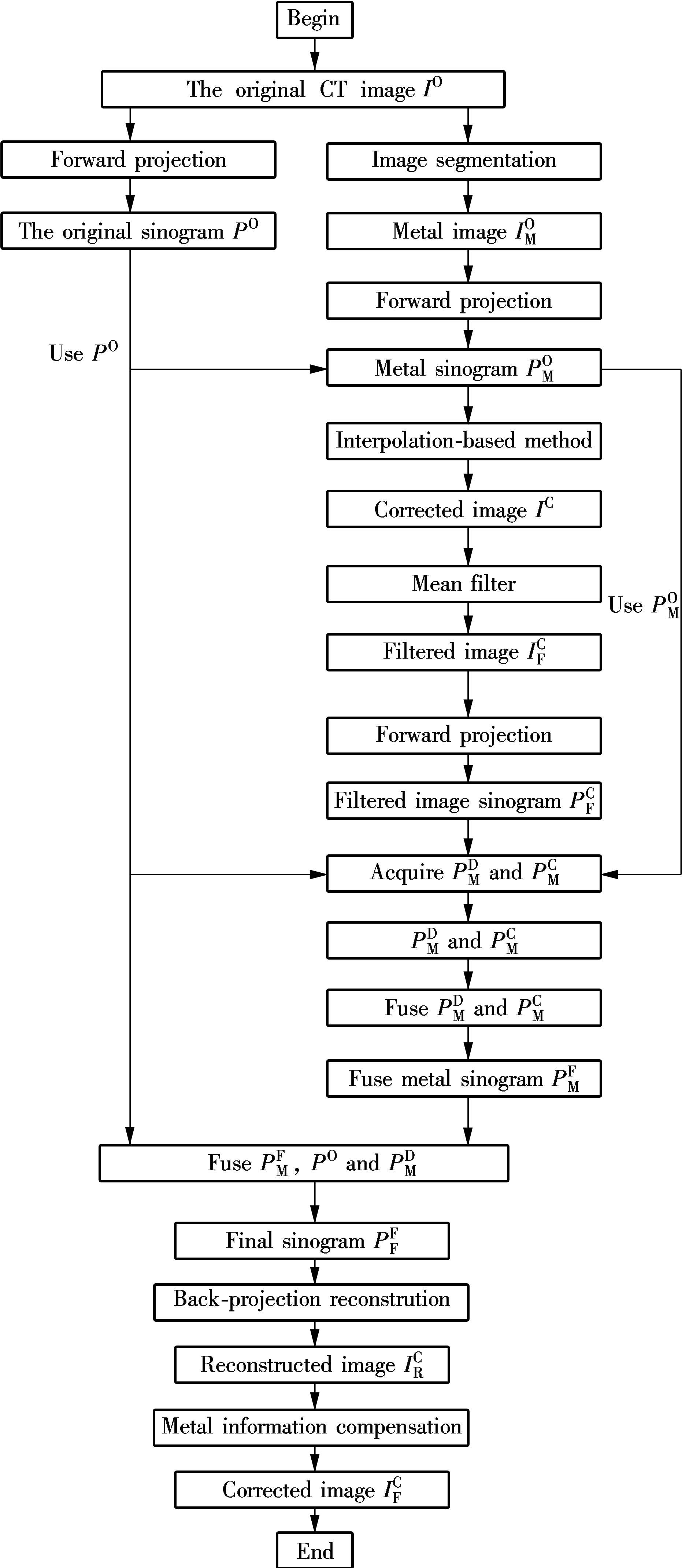
Fig.1 Flowchart of the proposed algorithm
1.1 Image segmentation and interpolation-based method correction
In the first step, the original CT image IO is segmented into metal image ![]() and no-metal image
and no-metal image ![]() by the pre-set threshold (The value is 2 000 in the experiments). Then, the original CT image IO and metal image
by the pre-set threshold (The value is 2 000 in the experiments). Then, the original CT image IO and metal image ![]() are forward projected into the original projection sinogram PO and metal projection sinogram
are forward projected into the original projection sinogram PO and metal projection sinogram ![]() , respectively. Finally, the interpolation-based correction method[1] is used to correct the original CT image IO in corrected image IC.
, respectively. Finally, the interpolation-based correction method[1] is used to correct the original CT image IO in corrected image IC.
1.2 Mean filter
During the stage of applying the interpolation-based correction method when correcting the original CT image IO, some new artifacts are introduced in the corrected CT image IC.
As a result,serious loss of edge structure near the metal can be seen from the corrected CT image IC. Therefore, to preserve the edge structure and suppress the new introduced artifacts near the metal in the corrected CT image IC, the mean filter is applied in the corrected CT image IC. The pixel gray values VF(i,j)(i=1,2,…,M; j=1,2,…,N, where M and N denote the number of rows and columns in the CT image, respectively.) in the filtered CT image are the average pixel gray values around the pixel (i,j) in the corrected CT image IC.
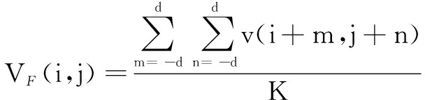
(1)
where K is the pixel number around the pixel (i,j) in the corrected CT image IC; d is equal to 20 for the experiments in this paper. v(i+m,j+n) is computed as
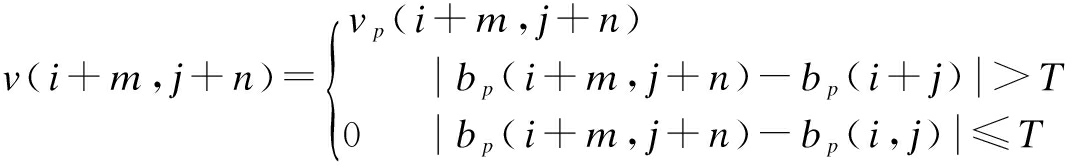
(2)
where T should be properly selected to preserve the edge structure and suppress the newly introduced artifacts (T=200 in the experiments); ![]() denotes the filtered image.
denotes the filtered image.
1.3 Sinogram fusion
After mean filtering, the filtered image ![]() is forward projected into a filtered sinogram
is forward projected into a filtered sinogram ![]() . First, according to the position of metal sinogram
. First, according to the position of metal sinogram ![]() in the original sinogram PO and filtered image sinogram
in the original sinogram PO and filtered image sinogram ![]() , the corresponding part
, the corresponding part ![]() in the original sinogram PO and
in the original sinogram PO and ![]() in the filtered image sinogram
in the filtered image sinogram ![]() can be acquired from PO and
can be acquired from PO and ![]() , respectively. Then, the two sinograms
, respectively. Then, the two sinograms ![]() and
and ![]() are fused into the fused metal sinogram
are fused into the fused metal sinogram ![]() according to a certain proportion. Finally, the final sinogram
according to a certain proportion. Finally, the final sinogram ![]() can be acquired by fusing the sinograms
can be acquired by fusing the sinograms ![]() , PO and
, PO and ![]() .
.
1.4 Back-projection reconstruction and metal information compensation
After acquiring the final sinogram ![]() , the artifacts-reduced image
, the artifacts-reduced image ![]() is obtained by reconstructing
is obtained by reconstructing ![]() with the filter back-projection reconstruction algorithm. Finally, the final corrected image
with the filter back-projection reconstruction algorithm. Finally, the final corrected image ![]() can be obtained by compensating the metal objects segmented from the original image in the reconstructed image
can be obtained by compensating the metal objects segmented from the original image in the reconstructed image ![]() .
.
To evaluate the performance of the proposed correction method, the experiments are performed on clinical images. In this section, the effects of fusion ratios on the corrected images and comparison with the interpolation-based correction method are provided.
2.1 Corrected images with different ratios
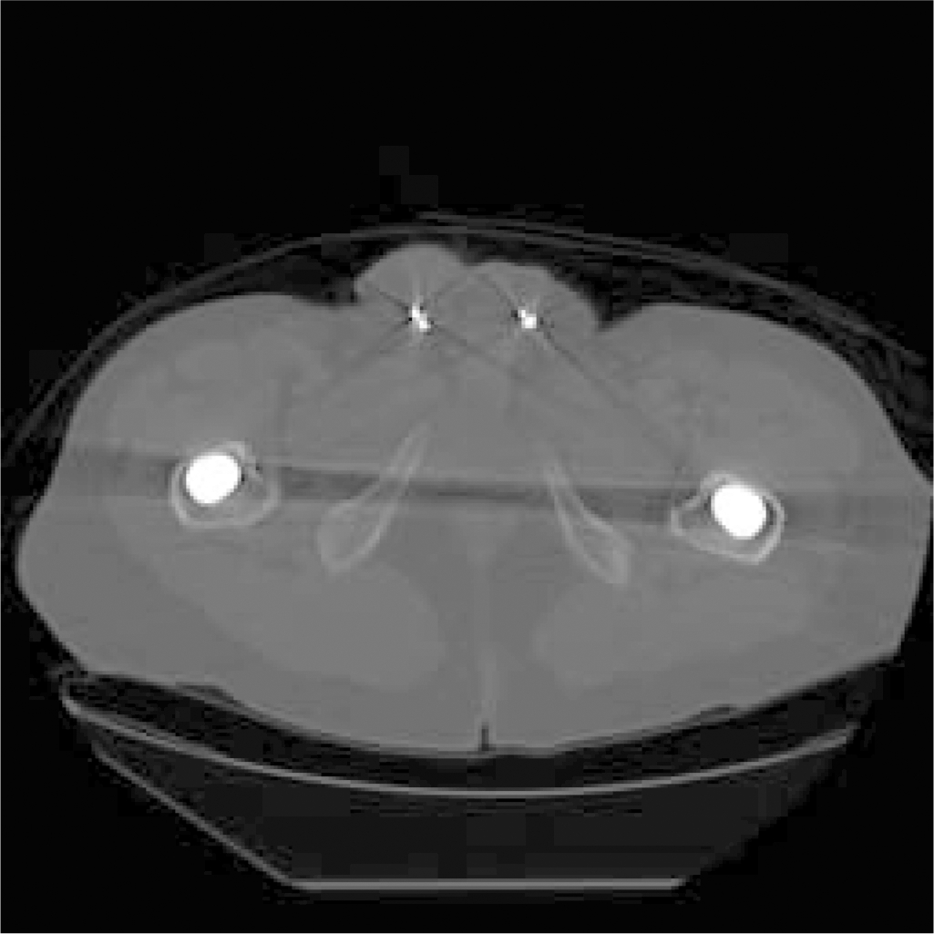
In order to demonstrate the effect of fusion ratio on the corrected images, Fig.2 shows the original image and corrected images with different fusion ratios. Fig.2 (a) is the original image. Figs.2 (b) to (f) are the corrected images with different fusion ratios. As can be seen from Fig.2 (a), the original image involves some metal artifacts. With the increase of ratios from 0, 0.25, 0.5, 0.75 to 1, the corrected images become more and more clear.

(a)
(b)
(c)
(d)
(e)

(f)
Fig.2 Corrected images with different fusion ratios. (a) The original image; (b) R=0; (c) R=0.25; (d) R=0.5; (e) R=0.75; (f) R=1
2.2 Comparison with classical interpolation-based correction method
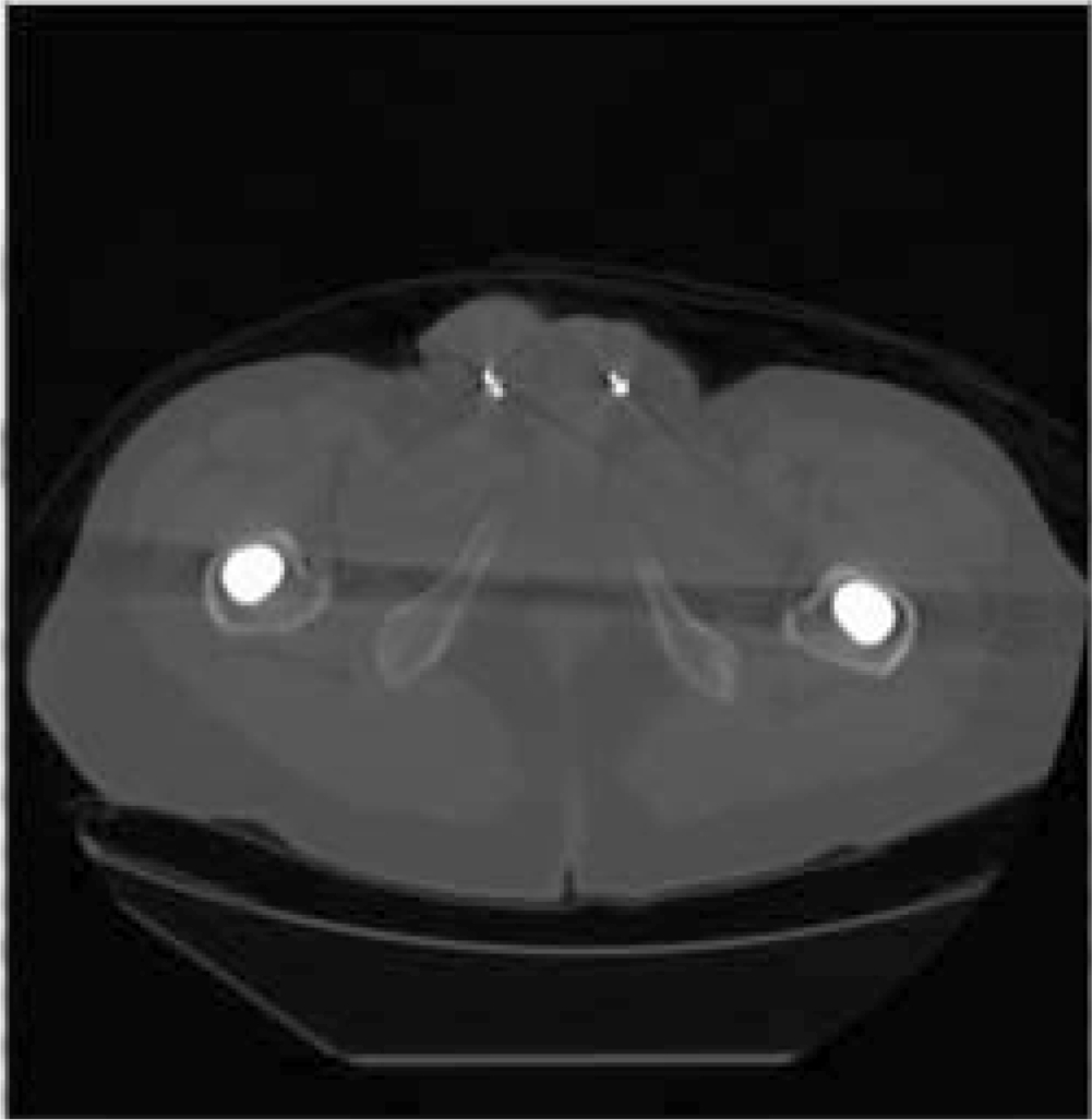
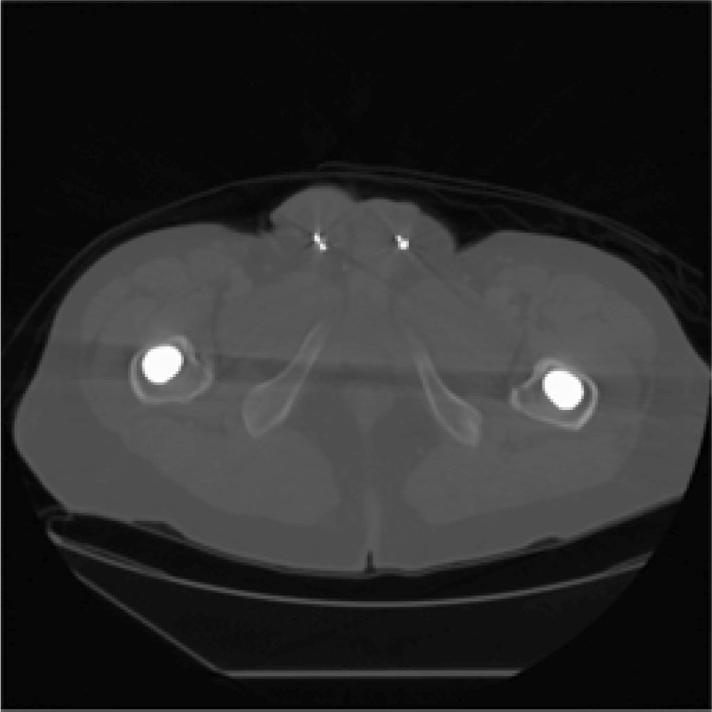
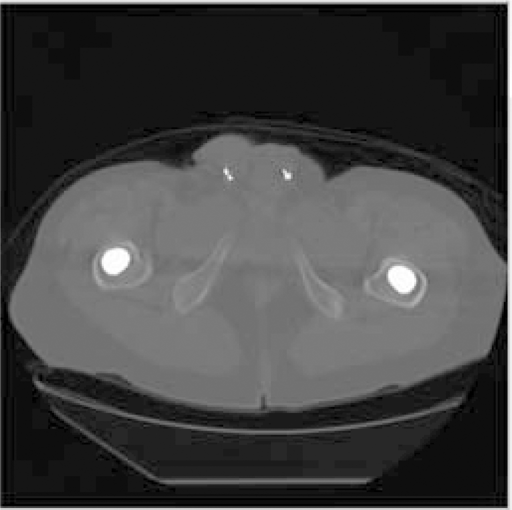
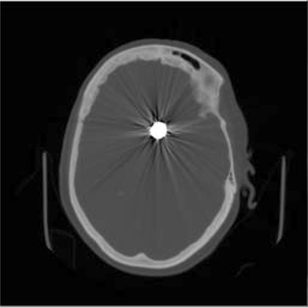
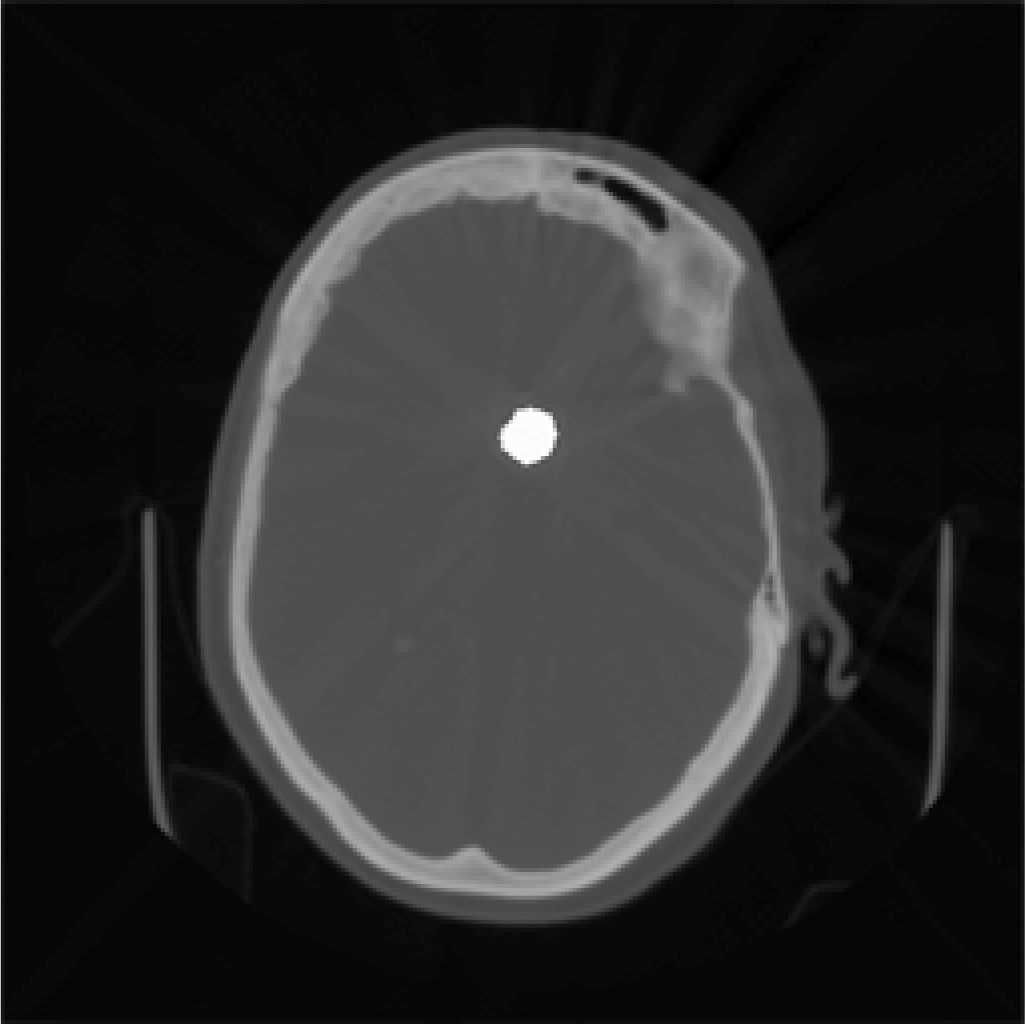
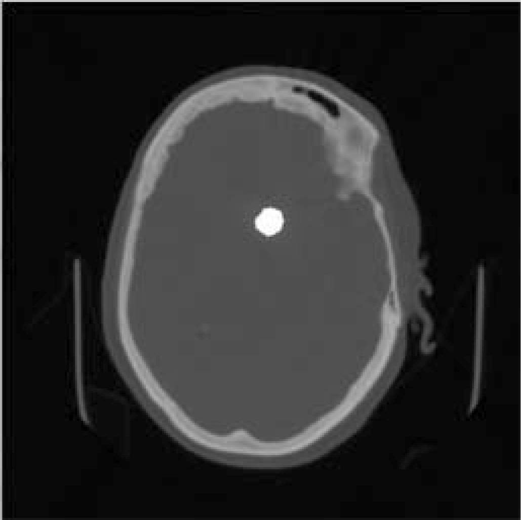
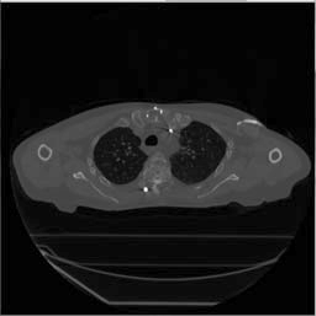
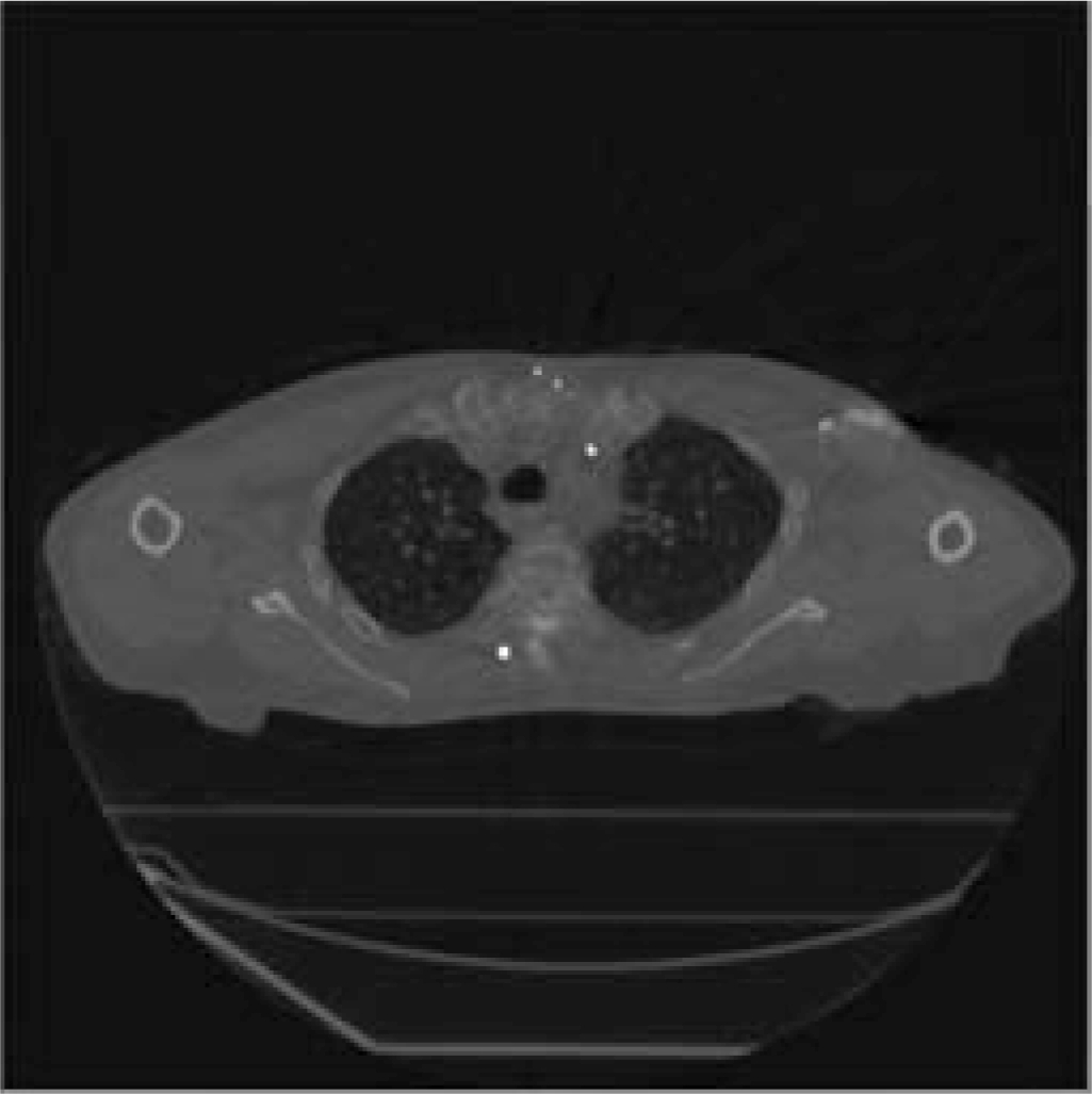
The interpolation-based correction method[1] is the classical metal artifacts correction method. Figs.3 and 4 show the comparisons among the original images, the corrected images using the interpolation-based correction method and the corrected images using the sinogram-based fusion correction method. The original images with format DICOM in Figs.3 and 4 come from revision radiology group[14].
(a)
(b)
(c)
Fig.3 The original images and corrected images of the head. (a) The original image; (b) The corrected image with the interpolation-based correction method; (c) The corrected image with the sinogram-based fusion correction method
(a)
(b)
(c)
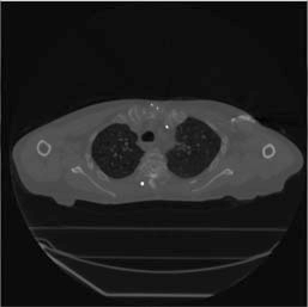
Fig.4 The original images and corrected images of the chest. (a) The original image; (b) The corrected image with the interpolation-based correction method; (c) The corrected image with the sinogram-based fusion correction method
As can be seen from subgraphs (a) in Fig.3 and Fig.4, the original CT images contain many metal artifacts. After using the interpolation-based correction method, the metal artifacts in subgraphs (b) of Fig.3 and Fig.4 have been greatly reduced. However, some artifacts remain in the corrected CT images. On the contrary, better correction effects can be seen from the subgraphs (c) in Fig.3 and Fig.4 using the proposed the sinogram-based fusion correction method.
In practice, the metal artifacts correction has always been a very thorny problem. To solve this problem, researchers have proposed some correction methods to remove the artifacts or reduce their influence on image quality. On the basis of the analysis of other metal artifact correction methods, we propose a sinogram-based fusion correction method to reduce the metal artifacts and compare the method with the classical metal artifact correction method. Experimental results demonstrate that the sinogram-based fusion correction method can provide better visual effects than the classical metal artifact correction method. This will lay down a solid foundation for further research and clinical application in the future.
[1]Kalender W A, Hebel R, Ebersberger J. Reduction of CT artifacts caused by metallic implant [J]. Radiology, 1987, 164(2): 576-577. DOI:10.1148/radiology.164.2.3602406.
[2]Glover G H, Pelc N J. An algorithm for the reduction of metal clip artifacts in CT reconstructions [J]. Medical Physics, 1981, 8(6): 799-807. DOI:10.1118/1.595032.
[3]Zhao S, Robertson D D, Wang G, et al. X-ray CT metal artifact reduction using wavelets: An application for imaging total hip prostheses [J]. IEEE Transactions on Medical Imaging, 2000, 19(12): 1238-1247. DOI:10.1109/42.897816.
[4]Paudel M R, Mackenzie M, Fallone B G, et al. Clinical evaluation of normalized metal artifact reduction in kVCT using MVCT prior images (MVCT-NMAR) for radiation therapy treatment planning [J]. International Journal of Radiation Oncology Biology Physics, 2014, 89(3): 682-689. DOI:10.1016/j.ijrobp.2014.02.040.
[5]Pessis E,Campagna R,Sverzut J M, et al. Virtual monochromatic spectral imaging with fast kilovoltage switching: Reduction of metal artifacts at CT [J]. Radiographics, 2013, 33(2): 573-583.
[6]Li Y J, Chen Y, Luo L M, et al. Fast CT metal artifacts correction based on derivative and region-based filling [J]. Journal of Medical Imaging and Radiation Oncology, 2011, 55(6): 535-541. DOI:10.1111/j.1754-9485.2011.02312.x.
[7]Prell D, Kyriakou Y, Beister M, et al. A novel forward projection-based metal artifact reduction method for flat-detector computed tomography [J]. Physics in Medicine and Biology, 2009, 54(21): 6575-6591. DOI:10.1088/0031-9155/54/21/009.
[8]Wang J, Wang S, Chen Y, et al. Metal artifact reduction in CT using fusion based prior image [J]. Medical Physics, 2013, 40(8): 081903. DOI:10.1118/1.4812424.
[9]Kim J, Nam H, Lee R. Development of a new metal artifact reduction algorithm by using an edge preserving method for CBCT imaging [J]. Journal of the Korean Physical Society, 2015, 67(1): 180-188. DOI:10.3938/jkps.67.180.
[10]Wuest W, May M S, Brand M, et al. Improved image quality in head and neck CT using a 3D iterative approach to reduce metal artifact [J]. American Journal of Neuroradiology, 2015, 36(10): 1988-1993. DOI:10.3174/ajnr.A4386.
[11]Axente M, Lee K, Paidi A, et al. Clinical evaluation of the iterative metal artifact reduction algorithm for CT simulation in radiotherapy[J]. Medical Physics, 2015, 42(3): 1170-1183. DOI:10.1118/1.4906245.
[12]Boudabbous S, Arditi D, Paulin E, et al. Model-based iterative reconstruction (MBIR) for the reduction of metal artifacts on CT [J]. American Journal of Roentgenology, 2015, 205(2): 380-385. DOI:10.2214/AJR.14.13334.
[13]Xia D, Roeske J C, Yu L, et al. A hybrid approach to reducing computed tomography metal artifacts in intracavitary brachytherapy [J]. Brachytherapy, 2005, 4(1): 18-23. DOI:10.1016/j.brachy.2004.11.001.
[14]Boas F E. Released a test set of DICOM images with metal artifacts [EB/OL]. (2011-11-23) [2016-07-01]. http://www.revisionrads.com/about.html/Download.
References:
摘要:针对金属伪影严重降低了CT图像中组织结构清晰度的问题,提出了基于正弦图融合的金属伪影校正方法.首先,通过预先设置的阈值对原始CT图像进行分割,得到金属图像.对原始CT图像和金属图像进行投影生成原始投影正弦图和金属投影正弦图.使用插值校正方法校正含有金属伪影的CT图像和均值滤波维持校正后CT图像的边界.滤波之后图像被投影成滤波图像正弦图.根据金属图像正弦图在原始正弦图和滤波后图像对应正弦图中的位置,分别得到正弦图![]() (在原始正弦图中)和
(在原始正弦图中)和![]() (在滤波后图像对应正弦图中).然后,按照一定的比例,将
(在滤波后图像对应正弦图中).然后,按照一定的比例,将![]() 和
和![]() 融合成正弦图
融合成正弦图![]() ,并通过融合正弦图
,并通过融合正弦图![]() ,PO和
,PO和![]() 得到最终正弦图.最后,用滤波反投影重建算法将最终正弦图重建成校正之后的图像,并将金属信息补偿到校正图像上.临床图像上的实验表明:与经典金属伪影校正方法相比,所提出的基于正弦图融合方法在金属伪影去除和组织结构特征保存方面能够得到更好的效果.
得到最终正弦图.最后,用滤波反投影重建算法将最终正弦图重建成校正之后的图像,并将金属信息补偿到校正图像上.临床图像上的实验表明:与经典金属伪影校正方法相比,所提出的基于正弦图融合方法在金属伪影去除和组织结构特征保存方面能够得到更好的效果.
关键词:金属伪影;基于插值校正方法;正弦图融合;CT图像
中图分类号:TP391.41
Received:2016-11-05.
Foundation item:s:Open Research Fund of the Key Laboratory of Computer Network and Information Integration of Ministry of Education of Southeast University (No.K93-9-2014-10C), the Scientific Research Foundation of Education Department of Anhui Province (No.KJ2014A186, SK2015A433), the National Basic Research Program of China (973 Program) (No.2010CB732503).
Citation::Li Yuanjin, Shu Huazhong, Xiao Gang, et al. Sinogram fusion-based metal artifact correction method[J].Journal of Southeast University (English Edition),2017,33(2):145-149.
DOI:10.3969/j.issn.1003-7985.2017.02.004.
DOI:10.3969/j.issn.1003-7985.2017.02.004
Biographies:Li Yuanjin(1976—), male, doctor, associate professor; Shu Huazhong (corresponding author), male, doctor, professor, shu.list@seu.edu.cn.