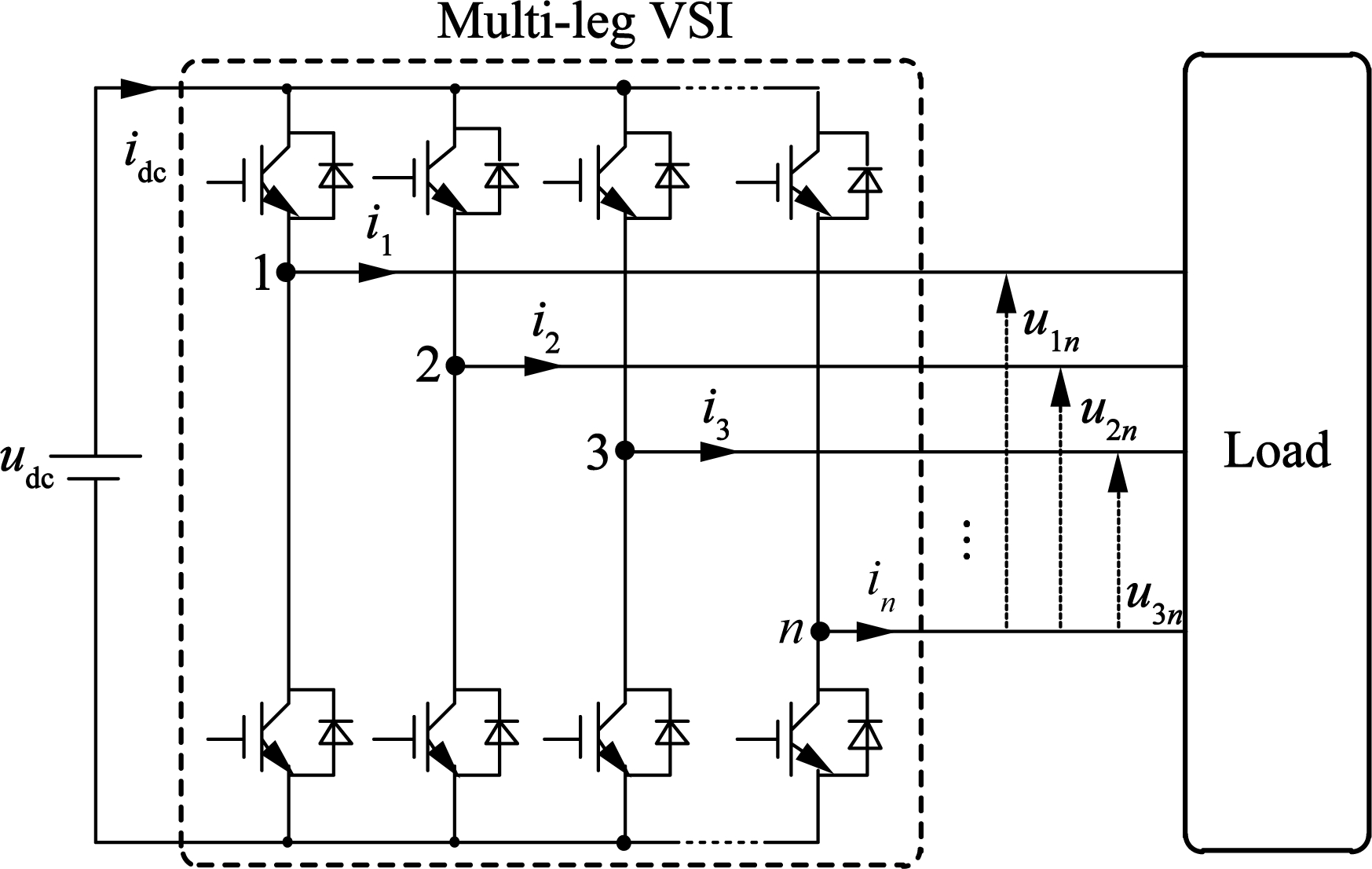
Fig.1 Structure of the studied system
Abstract:A generic pulse width modulation (PWM) strategy is proposed for the multi-leg voltage source inverter (VSI). First, the multi-leg VSI is modeled, which is independent from the load structure. Secondly, the proposed PWM strategy is deduced by inverting the mathematical model of the multi-leg VSI. According to the relationship between the leg number of VSIs and the phase number of electrical machines, the multi-leg VSI-fed machine drives are classified into two types: matched and unmatched applications. The leg numbers of VSIs and the phase number of electrical machines are equal in matched applications while they are different in unmatched applications. The existing PWM strategies cannot be directly used for both matched and unmatched applications. However, the proposed PWM strategy can be general for both matched and unmatched applications, and no modifications are required. The effectiveness of the proposed PWM strategy is verified by experimental results.
Key words:pulse width modulation (PWM); multi-leg voltage-source-inverter (VSI); carrier-based PWM; machine drives
Nowadays, pulse-width-modulation (PWM) voltage source inverters (VSIs) have been widely utilized in machine drives. One typical application is the three-phase machine drive, in which the three-phase electrical machine is fed by one three-leg VSI[1-6]. For the three-phase machine drive, space vector PWM (SVPWM) and carrier-based PWM (CBPWM) are the two most popular PWM strategies[7]. In SVPWM, a reference space vector is synthesized by two selected active space vectors and then the duration time of each selected active space vector is calculated. In CBPWM, modulation signals are compared with triangular carrier signals to generate switch states, while the classical modulation signals are the ratios between reference phase voltages and the half dc-link voltage. Meanwhile, the multi-leg VSI is also widely applied due to the development of multiphase electrical machines and the n-phase electrical machine is usually supplied by one n-leg VSI[8-13]. Correspondingly, the PWM strategies should be extended from three-leg VSIs to multi-leg VSIs. For the n-phase electrical machine, there will be 2n space vectors. Moreover, the number of space vectors increases with the phase number of electrical machines, which makes the implementation of multiphase SVPWM complex and difficult[14]. However, CBPWM has no such problems and it can be easily extended to control the multi-leg VSIs. Obviously, CBPWM is simpler than SVPWM in multi-leg VSI applications. An important feature that should be highlighted is that the leg number of VSIs is equal to the phase number of electrical machines in the above-mentioned machine drives, which is defined as matched applications in this paper. However, it is possible that the leg number of VSIs may be larger or smaller than the phase number of electrical machines, which is called unmatched applications in this paper. In Refs.[15-17], one three-leg VSI is used to control one two-phase load. In Refs.[18-20], two three-phase electrical machines are fed by one five-leg VSI. Furthermore, (2n+1)-leg VSI is extended to control n three-phase electrical machines[21]. Compared with matched applications, unmatched applications require a smaller leg number. Therefore, unmatched applications can be treated as the fault-tolerant topology of matched applications when some legs of matched applications fail[19-20].
In the matched application, it seems that one phase requires one leg and one leg only can connect one phase, which is the basic idea of the conventional CBPWM. Therefore, the conventional CBPWM cannot be directly used for unmatched applications and necessary modifications are required[16,18,20-21]. However, the modifications usually depend on the load structure, which reduces the universality of the modified PWM strategy. Besides, the modified CBPWM for unmatched applications can usually be no longer directly utilized for matched applications.
In this paper, a simple but generic PWM strategy is proposed for multi-leg two-level VSI, which is independent from the load structure. The proposed PWM strategy can be directly utilized for both matched and unmatched applications, and no modifications are required.
The structure of the n-leg two-level VSI is illustrated in Fig.1, in which the structure of the load is not described.
Fig.1 Structure of the studied system
The leg-n is selected as the reference leg, and the modulated voltage is calculated as
ukn=mknudc k∈{1,2,…,n},mkn∈[-1,1]
(1)
with
mkn=δk-δn δk∈[0,1]
(2)
where ukn is the modulated voltage between leg k and leg n; udc is the dc-link voltage; mkn is the modulated ratio between ukn and udc; δk is the duty cycle of leg k. Here, unn is a special modulated voltage between leg n and leg n and its value is zero. According to Eq.(1), the value of mnn is also zero.
udc is delivered to n modulated voltages by
U=Mudc
(3)
with
M=[m1n,m2n,…,mnn]T
(4)
U=[u1n,u2n,…,unn]T ukn∈[-udc,udc]
(5)
where M is the modulated ratio vector, and U is the modulated voltage vector.
The task of the proposed PWM strategy is to determine the duty cycle of each leg from the reference modulated voltages. The subscript “ref” is used to identify the reference value of the corresponding variable in this paper.
First, the reference modulated voltage vector Uref is obtained from a specific control method. For electrical machines, the control method may be field-oriented control or direct torque control.
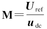
Secondly, the modulated ratio vector M can be given by inverting Eq.(3):
(6)
with
Uref=[u1n-ref,…,unn-ref]T ukn-ref∈[-udc,udc]
(7)
where ukn-ref is the reference modulated voltage between leg k and leg n.
For the n-leg VSI, n duty cycles are required to execute voltage commands. According to (2), the duty cycles can be calculated by
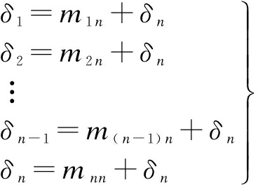
(8)
Since m1n, m2n,…, mnn have been determined by Eq.(6), δ1, δ2,…, δn only depend on the value of δn. The problem becomes how to determine the value of δn.
According to the available value range of duty cycles and ignoring the overmodulation situation, all the duty cycles must satisfy the following conditions:
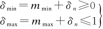
(9)
with
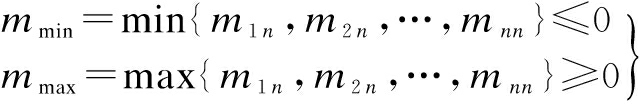
(10)
where mmax and mmin are the maximum and minimum modulated ratios, respectively; δmax and δmin are the maximum and minimum duty cycles, respectively.
According to (9), the value range of δn can be determined as
-mmin≤δn≤1-mmax
(11)
To determine the final value of δn, (11) is rewritten as
δn=-mmin+η[1-(mmax-mmin)]
(12)
where η is the selection coefficient, η∈[0,1], which becomes a new freedom degree instead of δn. Different η will result in different δ1, δ2,…, δn. Furthermore, different duty cycles will result in some different performances. Three different values of η are discussed in this paper:
1) Situation Ⅰ: η=0
In this situation, all the duty cycles obtain their minimum values, and at least one duty cycle is 0.
2) Situation Ⅱ: η=0.5
In this situation, all the duty cycles obtain their middle values, and 1-δmax=δmin.
3) Situation Ⅲ: η=1
In this situation, all the duty cycles obtain their maximum values, and at least one duty cycle is 1.
Situation Ⅰ and Situation Ⅲ are usually called discontinuous PWM [22], while Situation Ⅱ is usually called continuous PWM[22]. There will be two switching actions during one switching period if the duty cycle is in (0, 1). The discontinuous PWM has lower switching loss while the continuous PWM has lower harmonics. In this paper, Situation Ⅱ is selected for the harmonic-reducing purpose. Substituting η=0.5 into Eq.(12) gives
δn=0.5[1-(mmax+mmin)]
(13)
The flowchart diagram of the proposed PWM strategy is shown in Fig.2. The input of the proposed PWM strategy is the modulated voltage Uref, which depends on the selection of the reference leg. The final output of the proposed PWM strategy is the duty cycle vector δ(δ=[δ1, δ2,…, δn]T), which is outputted to control the n-leg two-level VSI.
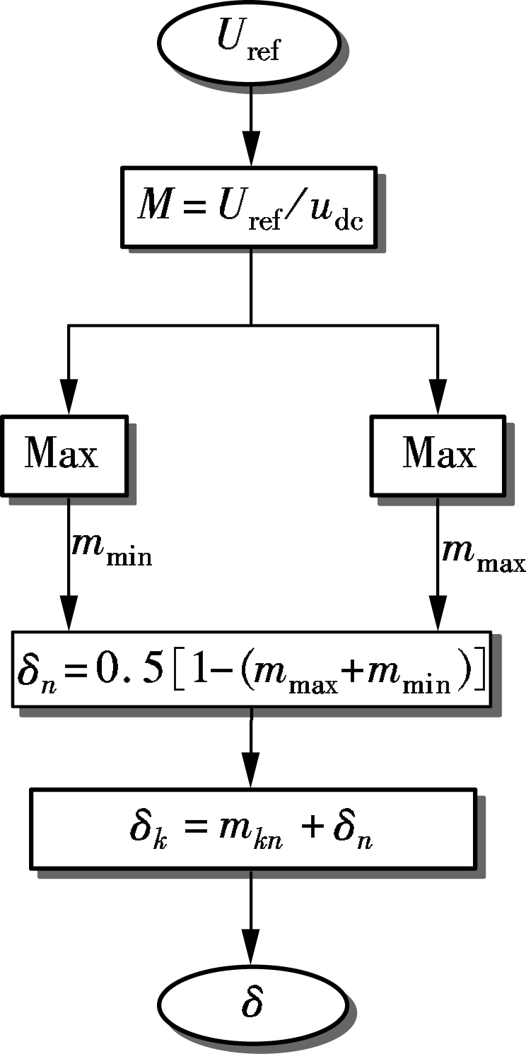
Fig.2 Flowchart diagram of the proposed PWM strategy
In this section, the universality of the proposed PWM strategy is analyzed by several typical applications.
3.1 Matched application
The typical matched application is that one n-phase electrical machine is fed by one n-leg VSI. Here, a five-phase drive system is taken as an example, in which one five-phase electrical machine is fed by one five-leg VSI as shown in Fig.3. The five-phase electrical machine has five phase windings (phase A, phase B, phase C, phase D, phase E) and the five-leg VSI has five legs (leg 1, leg 2, leg 3, leg 4, leg 5).
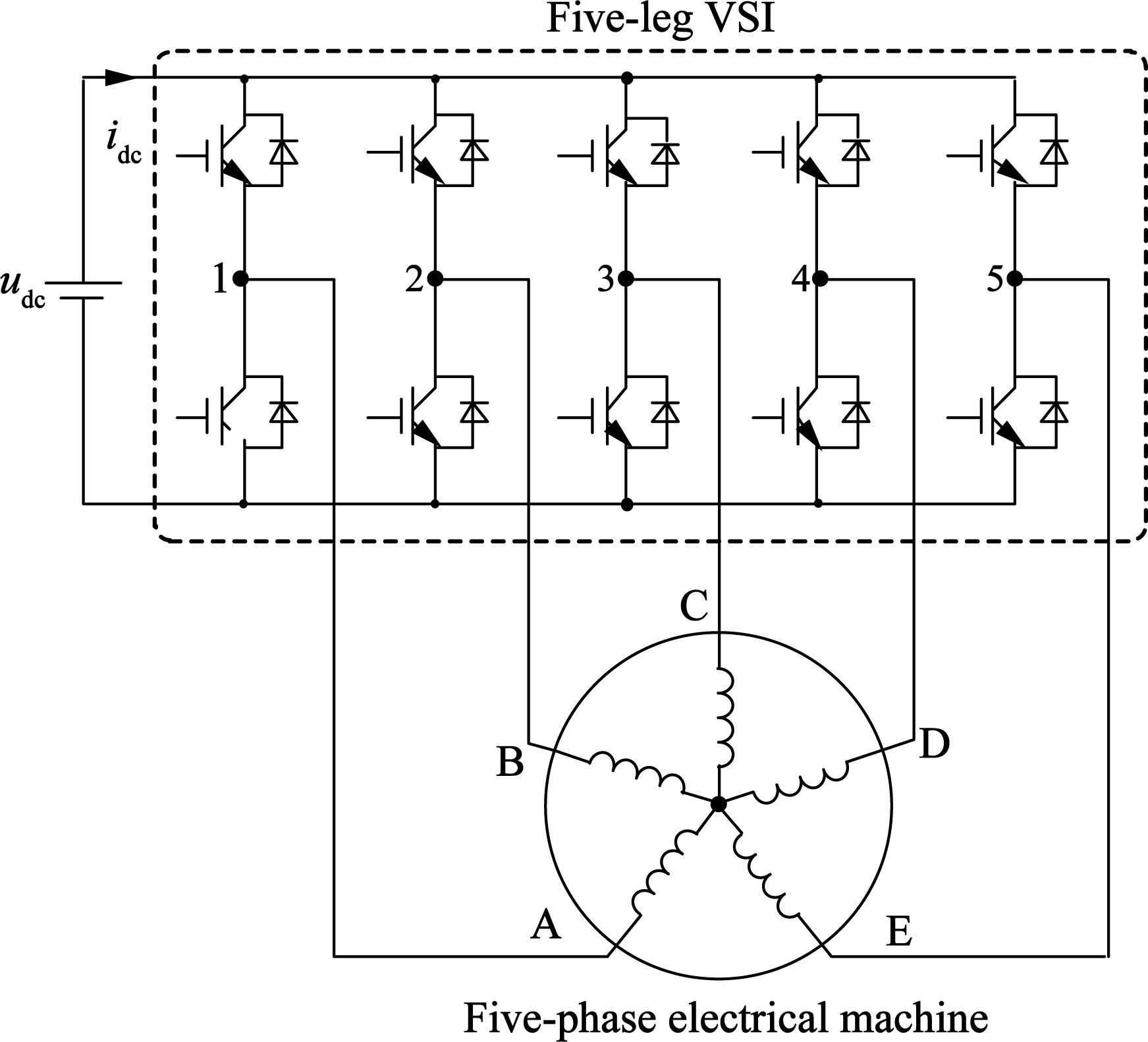
Fig.3 Example of a matched application
According to a specific control method, such as the field-oriented control, the reference phase voltages uA-ref, uB-ref, uC-ref, uD-ref, and uE-ref can be calculated. To use the proposed PWM strategy, one leg should be selected as the reference leg. Obviously, the five legs are completely the same and any leg can be selected as the reference leg. Here, leg 5 is selected as the reference leg and all reference modulated voltages can be calculated by
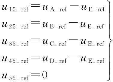
(14)
Based on Fig.2 and (14), the proposed PWM strategy can be easily used to execute the voltage commands (uA-ref, uB-ref, uC-ref, uD-ref, uE-ref) of the five-phase drive system. Of course, the proposed modulation strategy can be easily extended to any multiphase matched application.
3.2 Unmatched application
According to the proposed PWM strategy, all the modulated voltages should share one same reference leg. If there are x electrical machines and each electrical machine has y phase windings, the leg number n of the VSI can be calculated as
n=x(y-1)+1
(15)
The typical unmatched application is that two three-phase electrical machines (M1, M2) are fed by one five-leg VSI, as shown in Fig.4. The first electrical machine M1 has three phase windings (A1, B1, C1) while the other three phase windings (A2, B2, C2) belong to the second electrical machine M2. Phase A1, phase B1, phase A2, and phase B2 are connected by leg 1, leg 2, leg 5, and leg 4, respectively. Phase C1 and phase C2
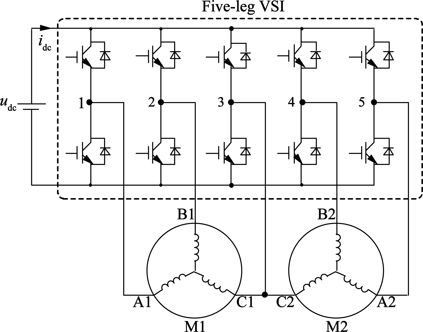
Fig.4 Example of an unmatched application
share leg 3.
According to a specific control method, such as the field-oriented control, the reference phase voltages (uA1-ref, uB1-ref, uC1-ref, uA2-ref, uB2-ref, and uC2-ref) can be calculated. As illustrated in Fig.4, leg 3 is different from the other four legs and it is the common leg shared by two electrical machines. Compared with the other four legs, leg 3 is a better candidate for the reference leg since the role of the common leg can simplify the calculation of the reference modulated voltages. Therefore, leg 3 is selected as the reference leg and all reference modulated voltages can be calculated by (16). Based on Fig.2 and (16), the proposed PWM strategy can also be easily used to execute the voltage commands uA1-ref, uB1-ref, uC1-ref, uA2-ref, uB2-ref, and uC2-ref of the studied unmatched drive system. Similarly, the proposed PWM strategy can be easily extended to any unmatched application.
(16)
To verify the effectiveness of the proposed PWM strategy, an experiment platform is developed, which contains a dSPACE DS1103 controller board and an IGBT-based five-leg VSI. The inputs for the dSPACE DS1103 controller are the measured phase currents and dc-bus voltage, and the feedback signal of the encoder. The switch states for the VSI are generated by the dSPACE DS1103 controller. A personal computer is employed for editing the control program and commanding the dSPACE DS1103 controller. The sampling frequency is 20 kHz. The switching frequencies of matched and unmatched applications are 2 and 10 kHz, respectively.
4.1 Experiment of matched applications
To verify the effectiveness of the proposed PWM strategy in matched applications, four RL loads (R=10 Ω, L=15 mH) are used to simulate the multiphase electrical machines from two-phase to four-phase, and the dc bus voltage is set to be 100 V. The detailed experiment platform is illustrated in Fig.5. The reference phase currents are symmetric sinusoidal waveforms, of which the magnitude and frequency are 1 A and 50 Hz, respectively. All the actual phase currents are measured by current sensors. First, the reference phase currents are compared with the corresponding measured phase currents to generate the reference phase voltages by PI controllers. Then, the reference modulated voltage vector Uref is obtained by the phase voltage references. According to Fig.2, the duty cycle vector δ can be calculated and outputted to control the multi-leg VSI.
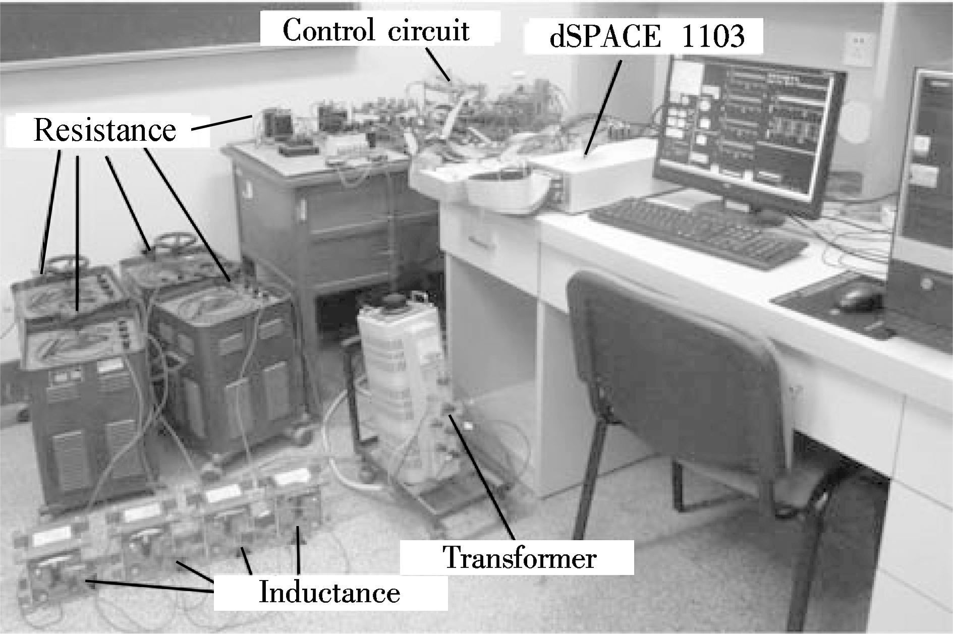
Fig.5 Experiment platform for matched applications
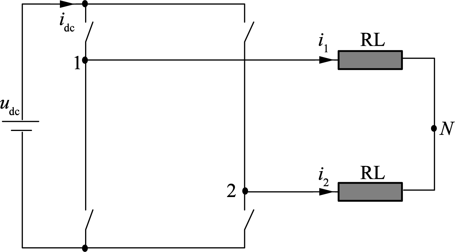
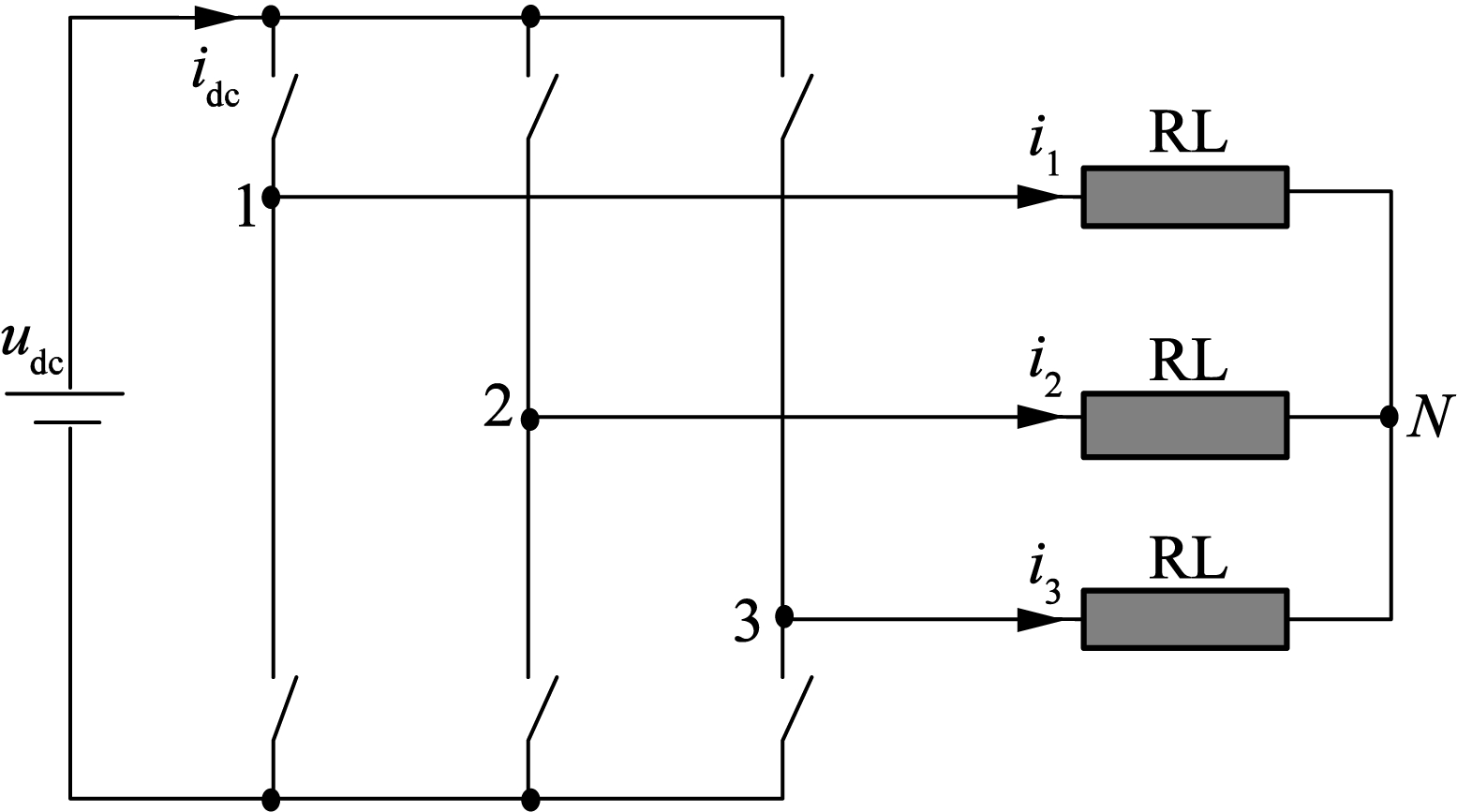
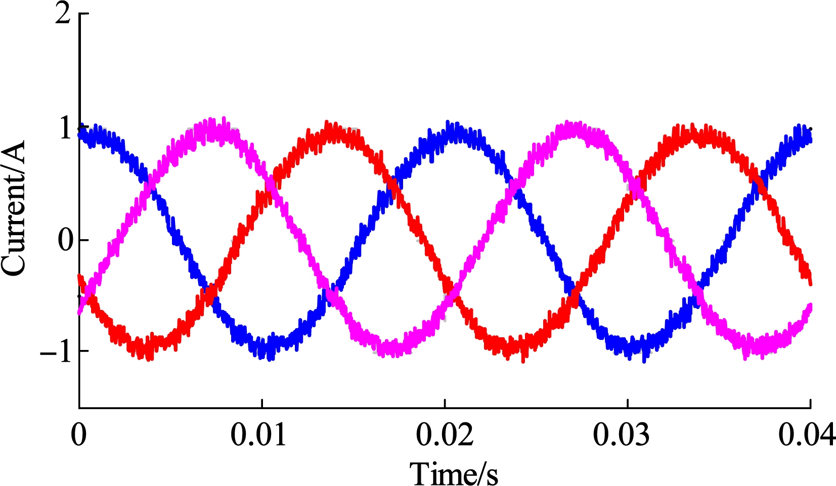
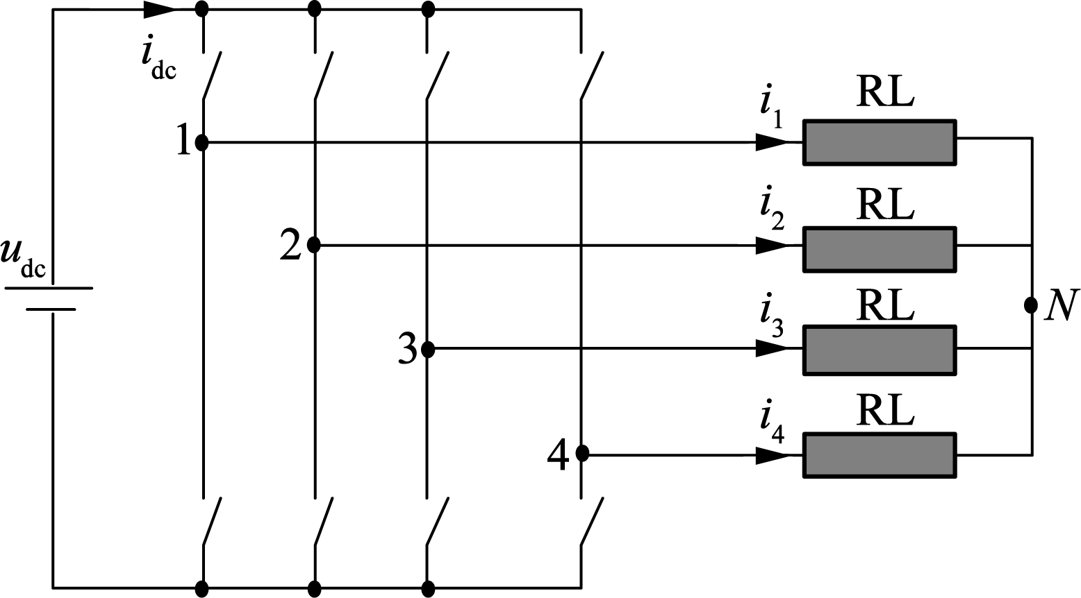
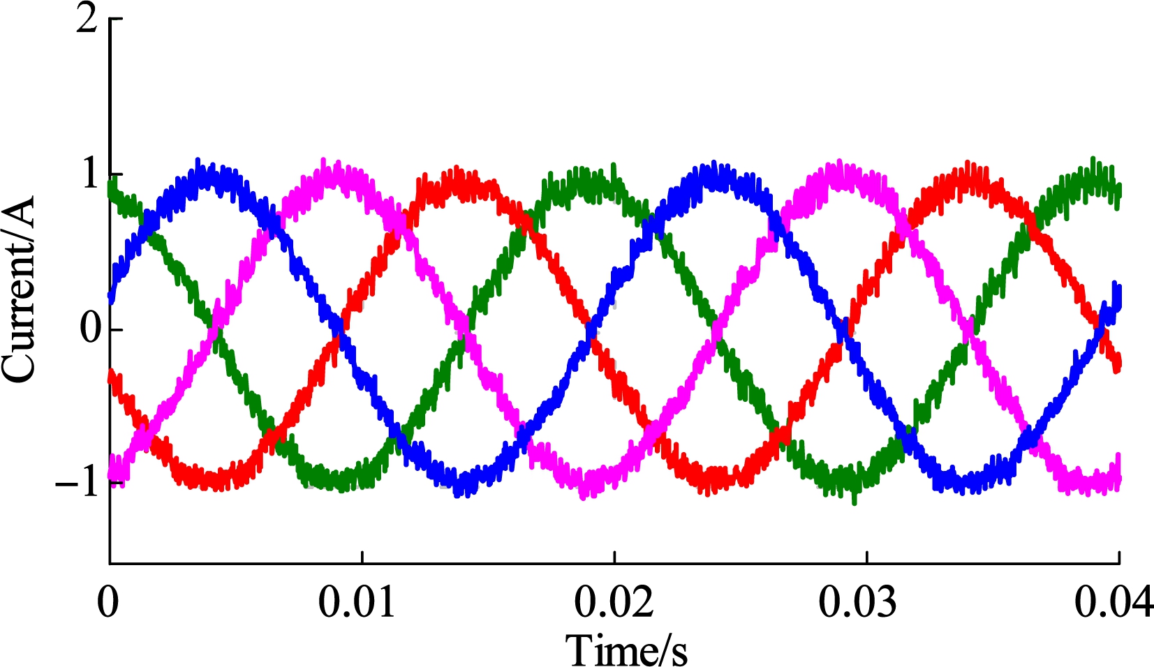
In this subsection, two-leg, three-leg and four-leg VSIs are deduced from the five-leg VSI to control two-phase, three-phase, four-phase RL loads, and some experiments are carried out. The structures of the three VSIs with different loads and experimental results are illustrated in Figs.6 to 8, respectively. All the actual currents are very sinusoidal, which can be verified by the smaller THD (total harmonic distortion) of phase currents. Taking Fig.7 as an example, the THD of phase currents is only 7.07%, which is obtained from the FFT (fast Fourier transformation) analysis. During the three experiments, the proposed PWM strategy can be directly applied without any modifications.
(a)

(b)
Fig.6 Two-leg VSI. (a) Structure; (b) Experimental results
4.2 Experiment of unmatched application
Fig.4 is taken as an example of unmatched applications to verify the effectiveness of the proposed PWM strategy in this section, and the detailed experiment platform is illustrated in Fig.9. M1 and M2 are two same permanent magnet synchronous machines (PMSMs) and they are connected by a standard 5.5 kW squirrel-cage induction machine (IM) with an encoder of 1 024 pulses per revolution. The parameters of PMSMs are listed in Tab.1. The two PMSMs are fed by the five-leg VSI. The drive system is supplied by a 250 V DC bus voltage. The load is realized by the close-loop torque control of the IM using the field oriented control.
(a)
(b)
Fig.7 Three-leg VSI.(a) Structure; (b) Experimental results
(a)
(b)
Fig.8 Four-leg VSI. (a) Structure; (b) Experimental results
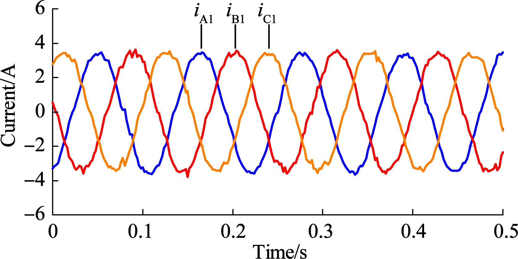
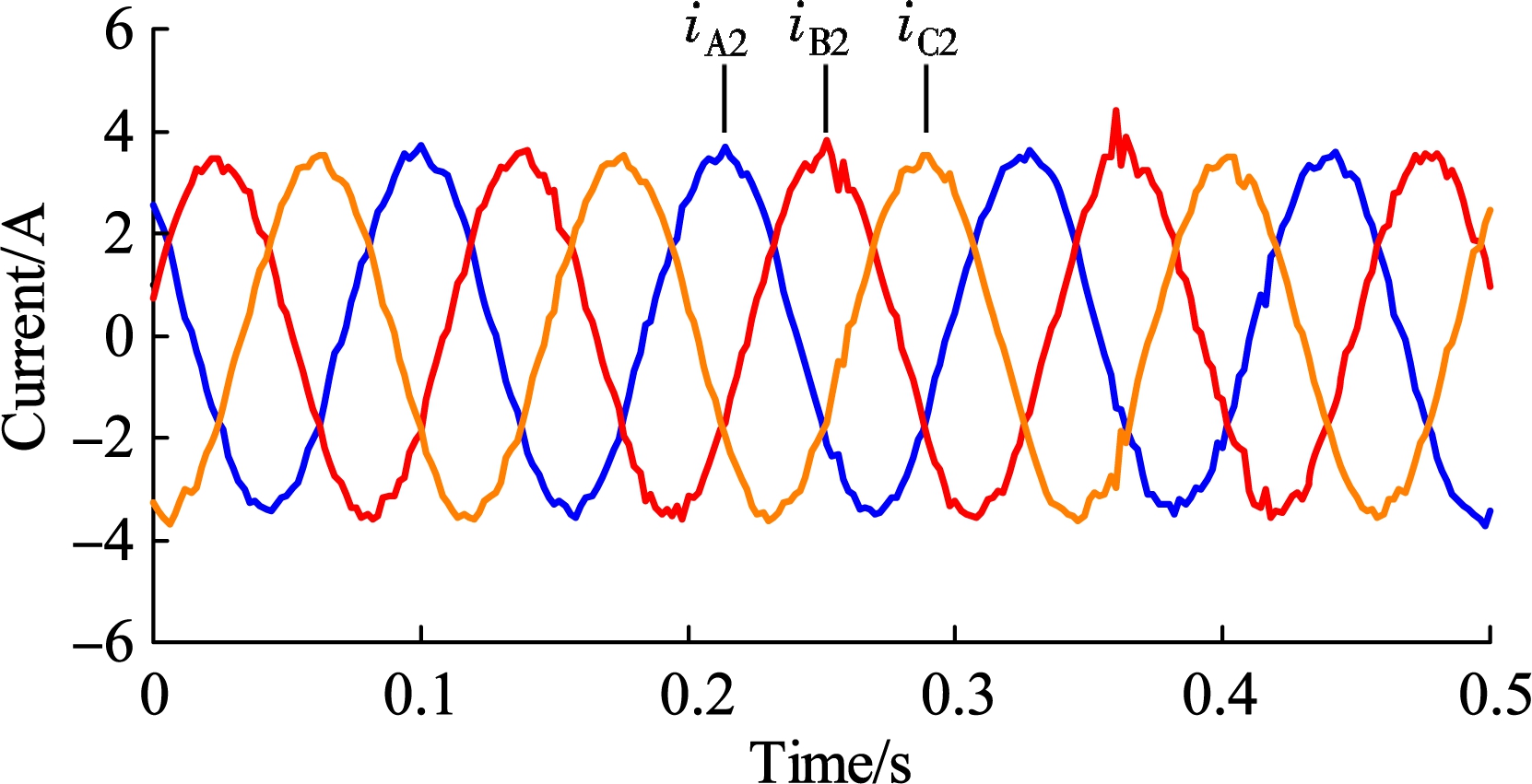
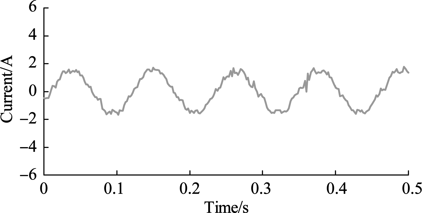
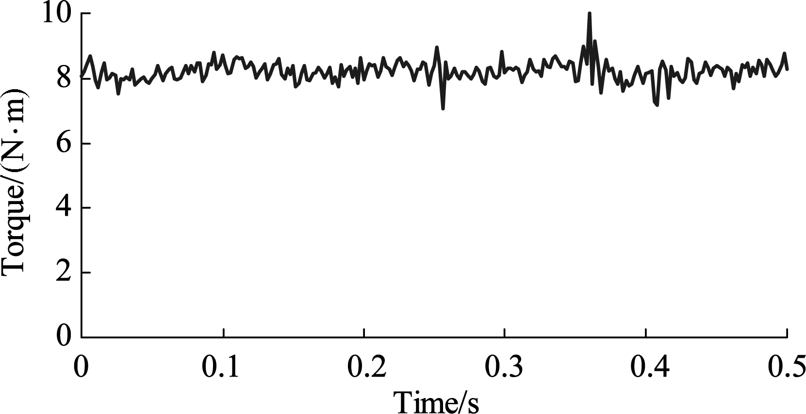
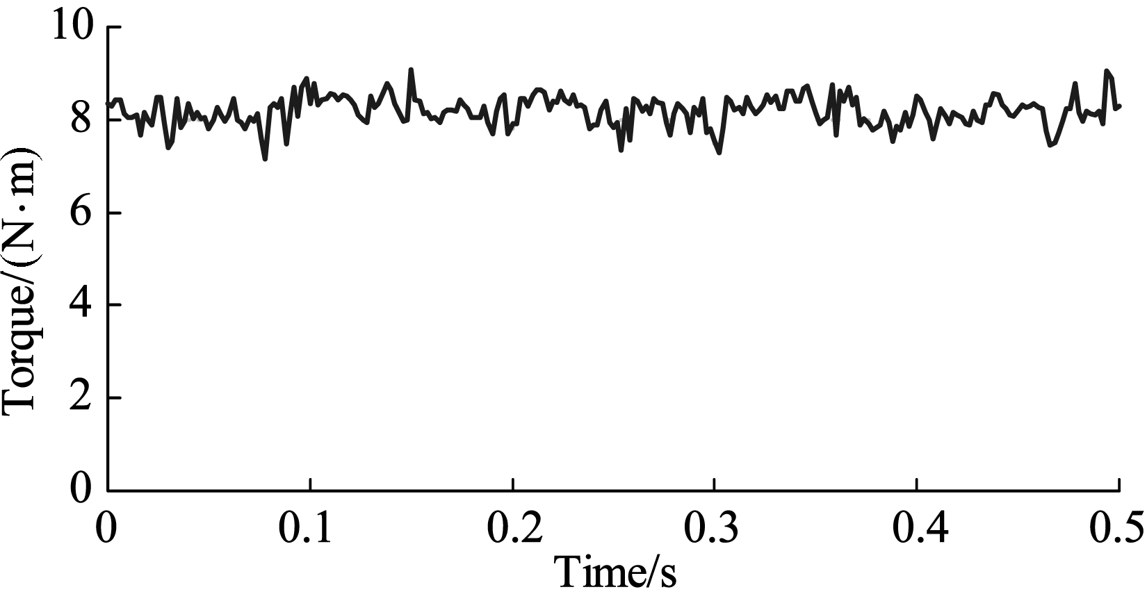
The experimental results are illustrated in Fig.10. The phase currents of M1 and M2 are, respectively, curved in Figs.10(a) and (b). The current of the common leg (leg 3) is the summation of iC1 and iC2. The torques of M1 and M2 are, respectively, shown in Figs.10(d) and (e).
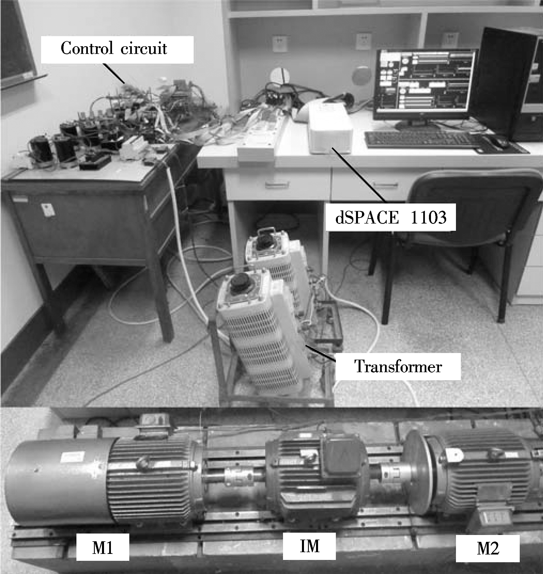
Fig.9 Experiment platform for unmatched applications
Tab.1 Parameters of PMSM
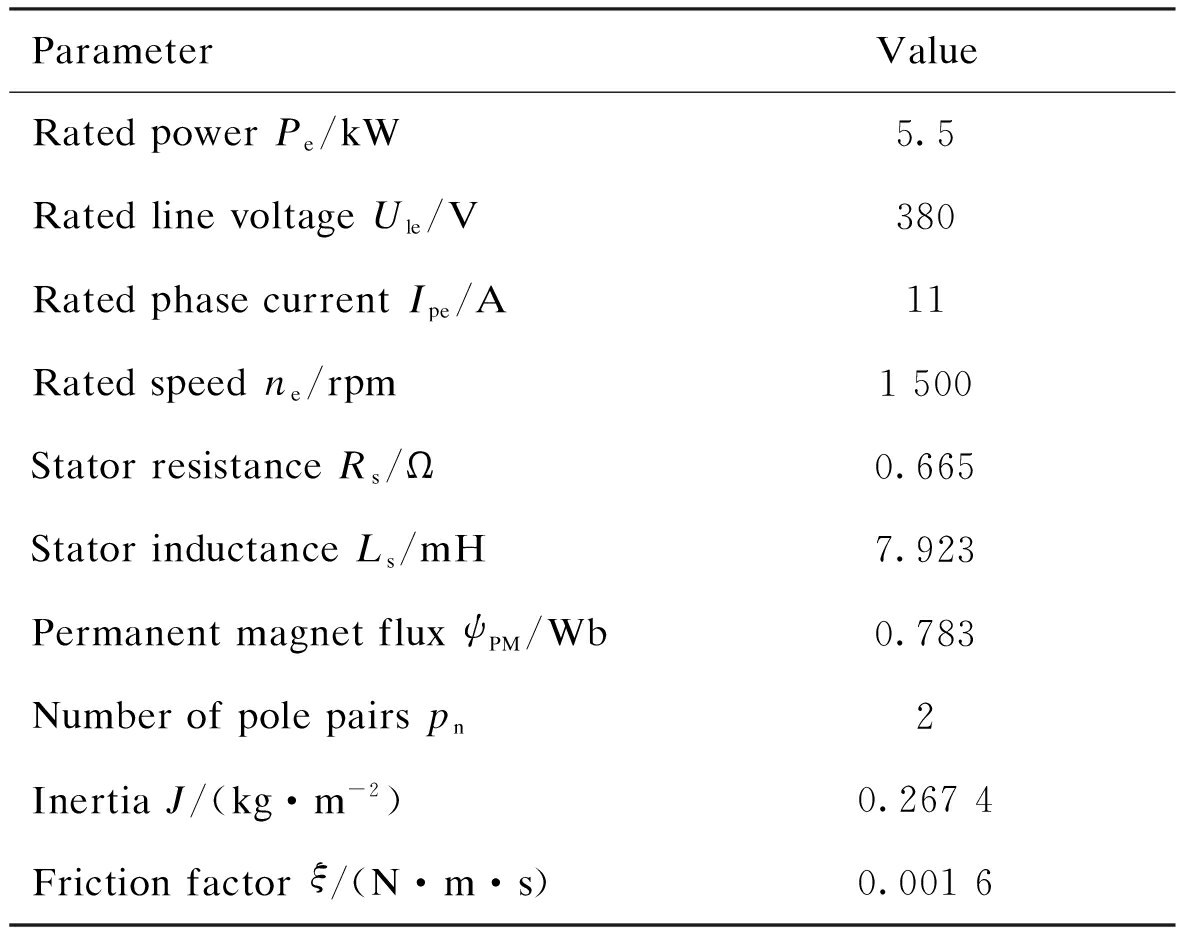
ParameterValueRatedpowerPe/kW5.5RatedlinevoltageUle/V380RatedphasecurrentIpe/A11Ratedspeedne/rpm1500StatorresistanceRs/Ω0.665StatorinductanceLs/mH7.923PermanentmagnetfluxψPM/Wb0.783Numberofpolepairspn2InertiaJ/(kg·m-2)0.2674Frictionfactorξ/(N·m·s)0.0016
In this paper, a generic PWM strategy is proposed for multi-leg two-level VSIs, which is based on modulated voltages. Compared with SVPWM, the CBPWM is simpler for multi-leg VSI. As is well-known, the conventional and existing modified CBPWM strategies cannot be directly used for both matched and unmatched applications. However, the proposed PWM strategy is independent from the load structure, and it can be directly used in both matched and unmatched applications. The proposed PWM strategy can be useful for the fast implementation of multi-leg VSI. Therefore, the researchers can concentrate on the development of the control method for multi-leg VSI since the proposed PWM strategy can be directly used.
(a)
(b)
(c)
(d)
(e)
Fig.10 Experimental results of unmatched applications. (a) Phase current of M1; (b) Phase current of M2; (c) Current of the common leg; (d) Torque of M1; (e) Torque of M2
[1]Seok J K, Kim S. Hexagon voltage manipulating control (HVMC) for AC motor drives operating at voltage limit[J]. IEEE Transactions on Industry Applications, 2015, 51(5): 3829-3837. DOI:10.1109/tia.2015.2416125.
[2]Alexandrou A D, Adamopoulos N K, Kladas A G. Development of a constant switching frequency deadbeat predictive control technique for field-oriented synchronous permanent-magnet motor drive[J]. IEEE Transactions on Industrial Electronics, 2016, 63(8): 5167-5175. DOI:10.1109/TIE.2016.2559419
[3]Wang W, Cheng M, Wang Y, et al. A novel energy management strategy of onboard supercapacitor for subway applications with permanent magnet traction system[J]. IEEE Transactions on Vehicular Technology, 2014, 63(6): 2578-2588. DOI:10.1109/tvt.2013.2293707.
[4]Cheng M, Hua W, Zhang J Z, et al. Overview of stator-permanent magnet brushless machines[J]. IEEE Transactions on Industrial Electronics, 2011, 58(11): 5087-5101. DOI:10.1109/tie.2011.2123853.
[5]Smith A N, Gadoue S M, Finch J W. Improved rotor flux estimation at low speeds for torque MRAS-based sensorless induction motor drives[J]. IEEE Transactions on Energy Conversion, 2016, 31(1): 270-282. DOI:10.1109/tec.2015.2480961.
[6]Sahoo S K, Bhattacharya T. Field weakening strategy for a vector-controlled induction motor drive near the six-step mode of operation[J]. IEEE Transactions on Power Electronics, 2016, 31(4): 3043-3051. DOI:10.1109/TPEL.2015.2451694.
[7]Zhou K L, Wang D W. Relationship between space-vector modulation and three-phase carrier-based PWM: A comprehensive analysis[J]. IEEE Transactions on Industrial Electronics, 2002, 49(1): 186-196. DOI:10.1109/41.982262.
[8]Lee C H T, Chau K T, Liu C. Design and analysis of a cost-effective magnetless multiphase flux-reversal DC-field machine for wind power generation[J]. IEEE Transactions on Energy Conversion, 2015, 30(4): 1565-1573. DOI:10.1109/tec.2015.2443155.
[9]Immovilli F, Bianchini C, Lorenzani E et al. Evaluation of combined reference frame transformation for interturn fault detection in permanent-magnet multiphase machines[J]. IEEE Transactions on Industrial Electronics, 2015, 62(3): 1912-1920. DOI:10.1109/tie.2014.2348945.
[10]Mohammadpour A, Parsa L. Global fault-tolerant control technique for multiphase permanent-magnet machines[J]. IEEE Transactions on Industry Applications, 2015, 51(1): 178-186. DOI:10.1109/TIA.2014.2326084.
[11]Chen X, Wang J, Patel V I, et al. A nine-phase 18-slot 14-pole interior permanent magnet machine with low space harmonics for electric vehicle applications[J]. IEEE Transactions on Energy Conversion, 2016, 31(3): 860-871. DOI:10.1109/tec.2016.2538321.
[12]Cheng M, Yu F, Chau K T, et al. Dynamic performance evaluation of a nine-phase flux-switching permanent-magnet motor drive with model predictive control[J]. IEEE Transactions on Industrial Electronics, 2016, 63(7): 4539-4549. DOI:10.1109/tie.2016.2547858.
[13]Guzman H, Barrero F, Duran M J. IGBT-gating failure effect on a fault-tolerant predictive current-controlled five-phase induction motor drive[J]. IEEE Transactions on Industrial Electronics, 2015, 62(1): 15-20. DOI:10.1109/tie.2014.2331019.
[14]Lopez O, Dujic D, Jones M, et al. Multidimensional two-level multiphase space vector PWM algorithm and its comparison with multifrequency space vector PWM method[J]. IEEE Transactions on Industrial Electronics, 2011, 58(2): 465-475. DOI:10.1109/tie.2010.2047826.
[15]Charumit C, Kinnares V. Discontinuous SVPWM techniques of three-leg VSI-fed balanced two-phase loads for reduced switching losses and current ripple[J]. IEEE Transactions on Power Electronics, 2015, 30(4): 2191-2204. DOI:10.1109/tpel.2014.2326773.
[16]Kumsuwan Y, Premrudeepreechacharn S, Kinnares V. A carrier-based unbalanced PWM method for four-leg voltage source inverter fed unsymmetrical two-phase induction motor[J]. IEEE Transactions on Industrial Electronics, 2013, 60(5): 2031-2041. DOI:10.1109/TIE.2012.2228138.
[17]Kinnares V, Charumit C. Modulating functions of space vector PWM for three-leg VSI-fed unbalanced two-phase induction motors[J]. IEEE Transactions on Power Electronics, 2009, 24(4): 1135-1139. DOI:10.1109/tpel.2008.2011906.
[18]Jones M, Vukosavic S N, Dujic D, et al. Five-leg inverter PWM technique for reduced switch count two-motor constant power applications[J]. IET Electric Power Applications, 2008, 2(5): 275-287. DOI:10.1049/iet-epa:20070497.
[19]Delarue P, Bouscayrol A, Semail E. Generic control method of multi-leg voltage-source-converters for fast practical implementation[J]. IEEE Transactions on Power Electronics, 2003, 18(2): 517-526. DOI:10.1109/tpel.2003.809349.
[20]Wang W, Cheng M, Zhang B, et al. A fault-tolerant permanent-magnet traction module for subway applications[J]. IEEE Transactions on Power Electronics, 2014, 29(4): 1646-1658. DOI:10.1109/tpel.2013.2266377.
[21]Jacobina C B, dos Santos E C, da Silva E R C, et al. Reduced switch count multiple three-phase AC machine drive systems[J]. IEEE Transactions on Power Electronics, 2008, 23(2): 966-976. DOI:10.1109/tpel.2007.915027.
[22]Ojo O, Gan D. Generalized discontinuous carrier-based PWM modulation scheme for multi-phase converter-machine systems[C]//IEEE Fourtieth IAS Annual Meeting. Hong Kong, China, 2005: 1374-1381.
References:
摘要:提出了一种适用于多桥臂电机驱动系统的通用型脉宽调制策略.首先,建立不依赖于负载结构的多桥臂逆变器数学模型.其次,根据多桥臂逆变器的数学模型逆向推导出通用型脉宽调制策略.根据逆变器桥臂和电机相绕组的数量关系,将电机驱动系统分为匹配和非匹配2种类型.其中,匹配型电机驱动系统中逆变器桥臂和电机相绕组的数量相等,而非匹配型电机驱动系统中逆变器桥臂和电机相绕组的数量不等.传统的脉宽调制策略无法直接同时适用于2种不同类型的多桥臂电机驱动系统.然而,所提的通用型脉宽调制策略可以在不做任何修改的情况下同时适用于2种不同类型的多桥臂电机驱动系统.最后,实验结果验证了所提通用型脉宽调制策略的有效性.
关键词:脉宽调制;多桥臂逆变器;载波型脉宽调制;电机驱动
中图分类号:TP391
Received:2016-12-05.
Foundation item:s:The National Natural Science Foundation of China (No.51607038), the Natural Science Foundation of Jiangsu Province (No.BK20160673), the National Basic Research Program of China (973 Program) (No.2013CB035603), China Postdoctoral Science Foundation (No.2015M581697, 2016T90401).
Citation::Wang Wei, Zhang Jinghao, Cheng Ming.A generic PWM strategy for multi-leg VSI-fed machine drives[J].Journal of Southeast University (English Edition),2017,33(2):189-195.
DOI:10.3969/j.issn.1003-7985.2017.02.011.
DOI:10.3969/j.issn.1003-7985.2017.02.011
Biography:Wang Wei (1985—),male,doctor, lecturer, wangwei1986@seu.edu.cn.