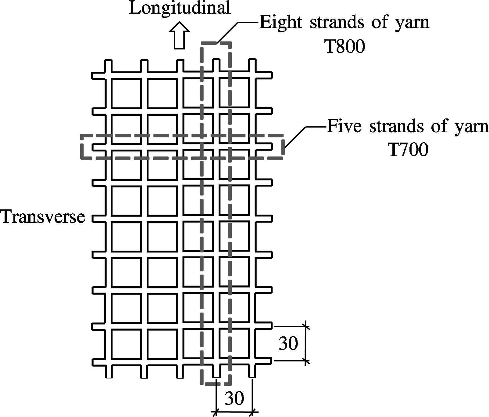
Fig.1 The form of the manufactured CFRP grid (units: mm)
Tab.1 Tested mechanical properties of the CFRP grid
Abstract:The effectiveness of carbon fiber reinforced polymer (CFRP) grids as the strengthening materials for a pre-damaged scaled tunnel model is experimentally investigated. First, the bond performances between the CFRP grid and the concrete under different types of adhesive and surface treatment were tested. The most efficient anchoring system was adopted for the subsequent scaled tunnel strengthening. Test results show that when the epoxy structural adhesive was used as the bonding material, the failure mode was CFRP grids rupturing, and the anchorage performance was optimal. When the polymer mortar was used as the adhesive, the surface treatments with anchored bolts and grooves can improve the bond performance, and the failure mode was sliding failure with the polymer mortar peeled off. After strengthening with CFRP grids, both the stiffness and the load capacity of the pre-damaged scaled tunnel model were improved. Additionally,
the results obtained by fiber bragg grating (FBG) sensors indicate that the strains across tunnel segments were reduced, and the overall performance of the tunnel was improved.
Key words:carbon fiber reinforced polymer (CFRP) grid; double-shear bond test; surface treatment; scaled tunnel model; relative displacement
Fiber reinforced polymers (FRPs) in the form of bars, sheets, and plates have been widely used in the strengthening of concrete structures for decades[1]. In recent years, FRP grids, as another form of FRP materials, have attracted increasing interest from researchers as both inner tensile reinforcements[2-6] and external bonded strengthening materials[7-10]. The properties of concrete beams, slabs and bridge decks that were reinforced or strengthened with FRP grids have been extensively investigated. Rahman et al.[6] tested the performance of bridge decks reinforced with carbon fiber reinforced polymer (CFRP) grids under service load and ultimate load. It was found that the construct ability of CFRP grids in strengthening bridge decks was good. The deflection and stress were both reduced as indicated by the cyclic loading test results. Researchers also tested the static and seismic performance of concrete columns reinforced or strengthened with FRP grids[11-12]. Wu et al.[11] conducted an axial compression loading test on concrete columns wrapped by FRP grids; it was concluded that both the strength and ductility of the confined column were clearly improved, and the external bonded FRP grids can effectively increase the seismic performance of RC concrete structures.
With the expanding body of research, the FRP grid is regarded as one item that can be effectively used in tunnel strengthening due to its properties of being lightweight, of high strength, and good durability. It can not only reinforce the strength and stiffness of the cross-section of the tunnel but also improve the longitudinal flexural stiffness of it and thus lower the impact of uneven settlement on the tunnel. For a subway tunnel in a city, the strengthening can only be carried out during the suspension of operation of the subway; the period of the suspension of operation is only approximately three to four hours every day. This limited period requires that the strengthening method must have a high construction efficiency. When the FRP grids are used in tunnel strengthening, a light grid can be easily fixed onto the sprayed substrate concrete using a compressed air gun; subsequently, a thin layer of concrete is sprayed as cover. Technically, it is mature, simple and convenient. Thus, FRP grids have a good prospect for application in tunnel strengthening.
To further investigate the feasibility of using FRP grids as a strengthening material in a tunnel, CFRP grids are manufactured in the laboratory, and the bond performance of CFRP grids with concrete under different adhesives and surface treatments are investigated. Also, a loading test is conducted on a CFRP grid strengthened scaled tunnel model in the laboratory.
1.1 Materials
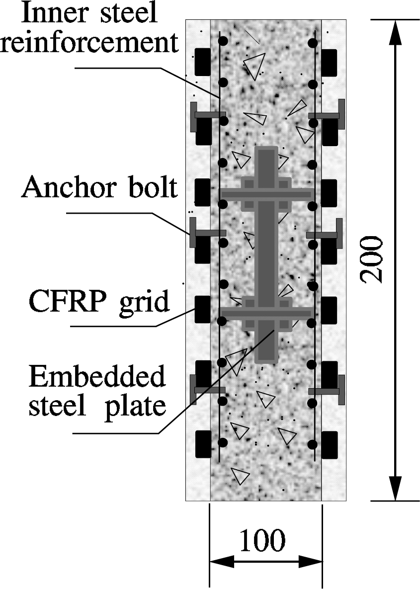
The CFRP grid used in this paper was manufactured using the vacuum-assisted resin transfer molding (VARTM) technique in the laboratory. The carbon fibers were provided by the Japan Toray Company, and the resin matrix of vinyl ester was provided by the Yabang Investment Holding Group Co., LTD. As shown in Fig.1, there were eight strands of T800 yarn in the longitudinal direction and five strands of T700 yarn in the transverse direction. The grid spacing was 30 mm×30 mm, and the cross-section of the single bar was 3 mm (width)×2 mm (thickness) in both directions. The tested mechanical properties in the two directions are shown in Tab.1.
Fig.1 The form of the manufactured CFRP grid (units: mm)
Tab.1 Tested mechanical properties of the CFRP grid
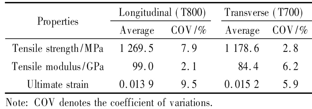
PropertiesLongitudinal(T800)Transverse(T700)AverageCOV/%AverageCOV/%Tensilestrength/MPa1269.57.91178.62.8Tensilemodulus/GPa99.02.184.46.2Ultimatestrain0.01399.50.01525.9Note:COVdenotesthecoefficientofvariations.
The epoxy structural adhesive used was type TLS-401, which was provided by the Nanjing Telesun S&T Industry Co., LTD. The performance specifications of TLS-401 are listed in Tab.2. The polymer mortar was made by mixing dry powder and the liquid matrix at a mass ratio of 3∶1. The dry powder was comprised of cement∶coarse sand∶fine sand at a ratio of 2∶2∶1, and the liquid matrix was comprised of water∶acrylic-emulsion∶901 glue at a ratio of 2∶0.5∶0.9. The tested flexural strength was higher than 8.0 MPa, and the cohesive pulling strength was higher than 1.2 MPa.
Tab.2 The performance of the structural adhesive used in this paper (type TLS-401)
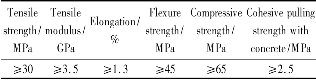
Tensilestrength/MPaTensilemodulus/GPaElongation/%Flexurestrength/MPaCompressivestrength/MPaCohesivepullingstrengthwithconcrete/MPa≥30≥3.5≥1.3≥45≥65≥2.5
1.2 Specimen design
1.2.1 Double-shear bond specimens
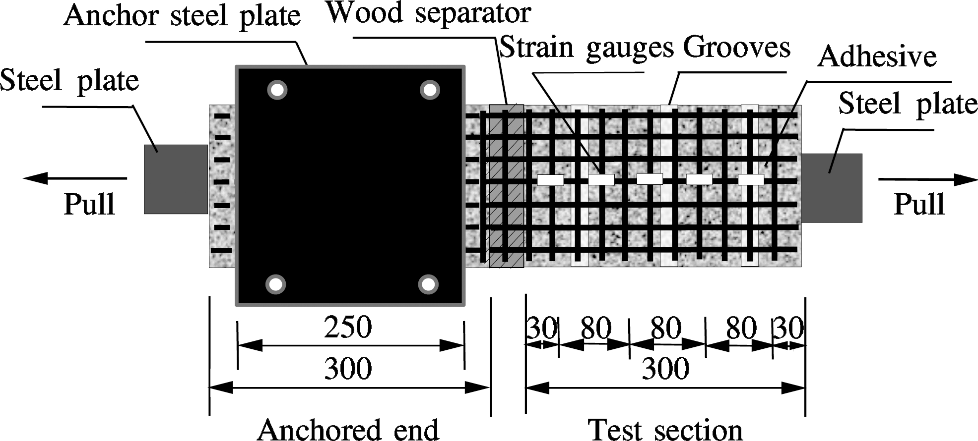
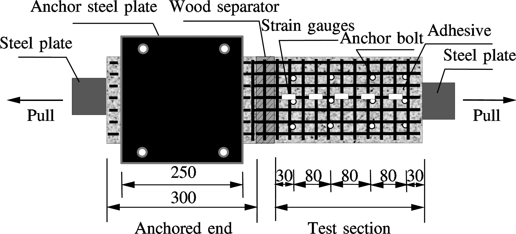
Fig.2 illustrates the specimens prepared for the double-shear bond tests; the sizes of concrete blocks were based on the research by Shi et al.[13]. The targeted concrete grade was C50, and the tested 28-day cube strength was 65.7 MPa. The test matrix are shown in Tab.3. To improve the bond performance, two types of surface treatments, i.e., grooves and anchor bolts, were adopted, as shown in Figs.2(a) and (c).
(a)
(b)
(c)
(d)
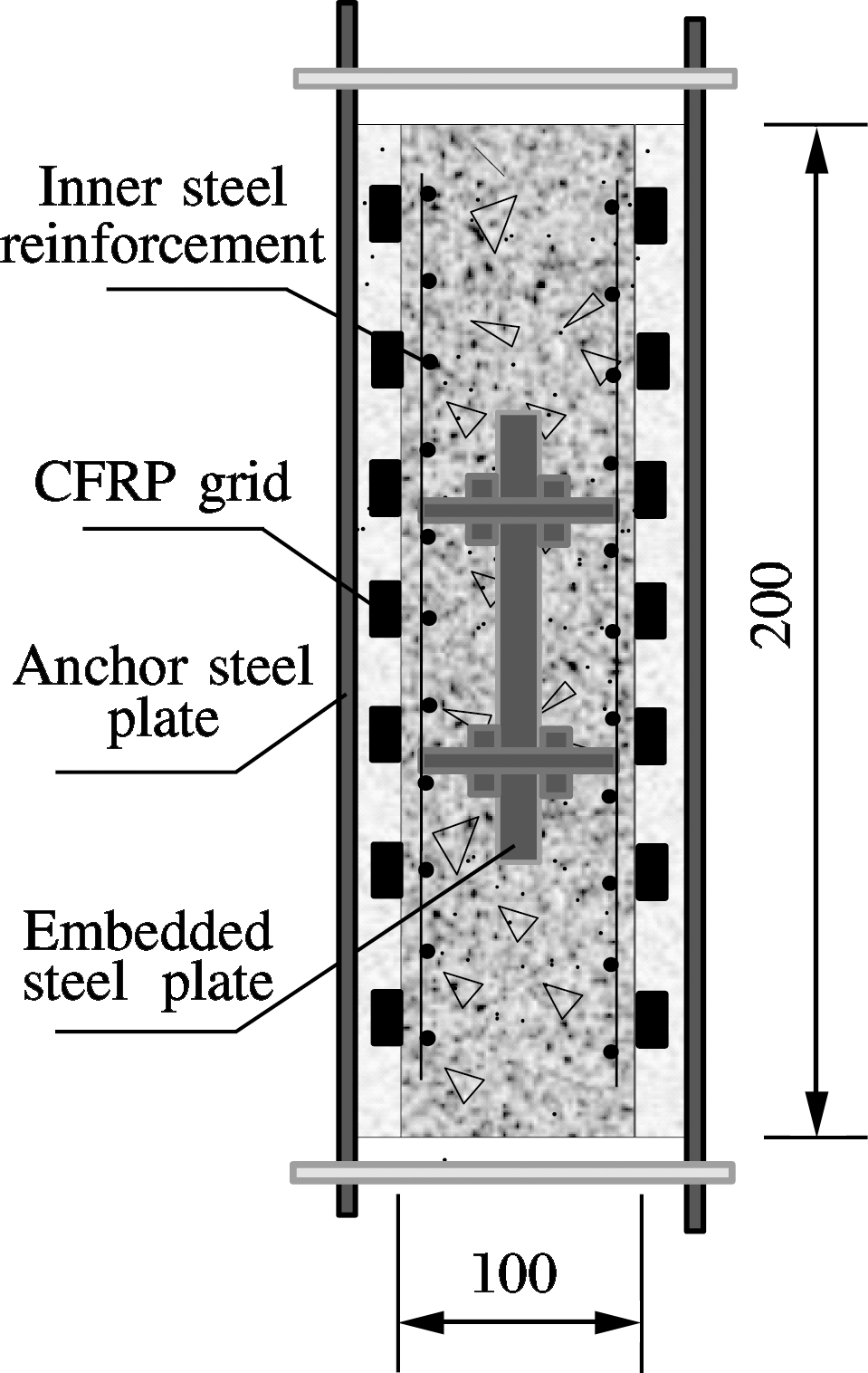
Fig.2 Schematic diagram of the double-shear bond test specimens (unit: mm). (a) Surface treatment with grooves; (b) Cross-section of the anchored end; (c) Surface treatment with anchor bolts; (d) Cross-section of the test section
Tab.3 Test matrix for the double-shear bond performance test

SpecimensTypeofadhesiveSurfacetreatmentGroovesAnchorboltsH0EpoxystructuraladhesiveNoNoHCEpoxystructuraladhesiveYesNoJMPolymermortarNoYesJCPolymermortarYesNoNote:Eachgroupcontainsthreeidenticalsamples
As shown in Fig.2, the CFRP grids were symmetrically attached to the two sides of the concrete block. Steel plates were embedded inside the concrete blocks and were connected to the machine grips when testing. The two concrete blocks were separated by a wood separator at the middle section. At one end, the concrete block was clamped by two steel plates, as shown in Fig.2(b), which formed the anchored end. The other end was used as the test section. The tests were conducted on the universal testing machine, and the loading speed was 0.8 mm/min. As shown in Figs.2(a) and (c), strain gauges were attached to the middle CFRP along the pull direction.
1.2.2 Scaled tunnel model
According to the analogous theory, a scaled tunnel model was manufactured[14]. Tab.4 shows a comparison of the parameters of the practical tunnel segment and the scaled model. The adopted scale similarity ratio was 8, and the stress scale similarity ratio was 1.
Tab.4 Parameters of the practical tunnel segment and its scaled model
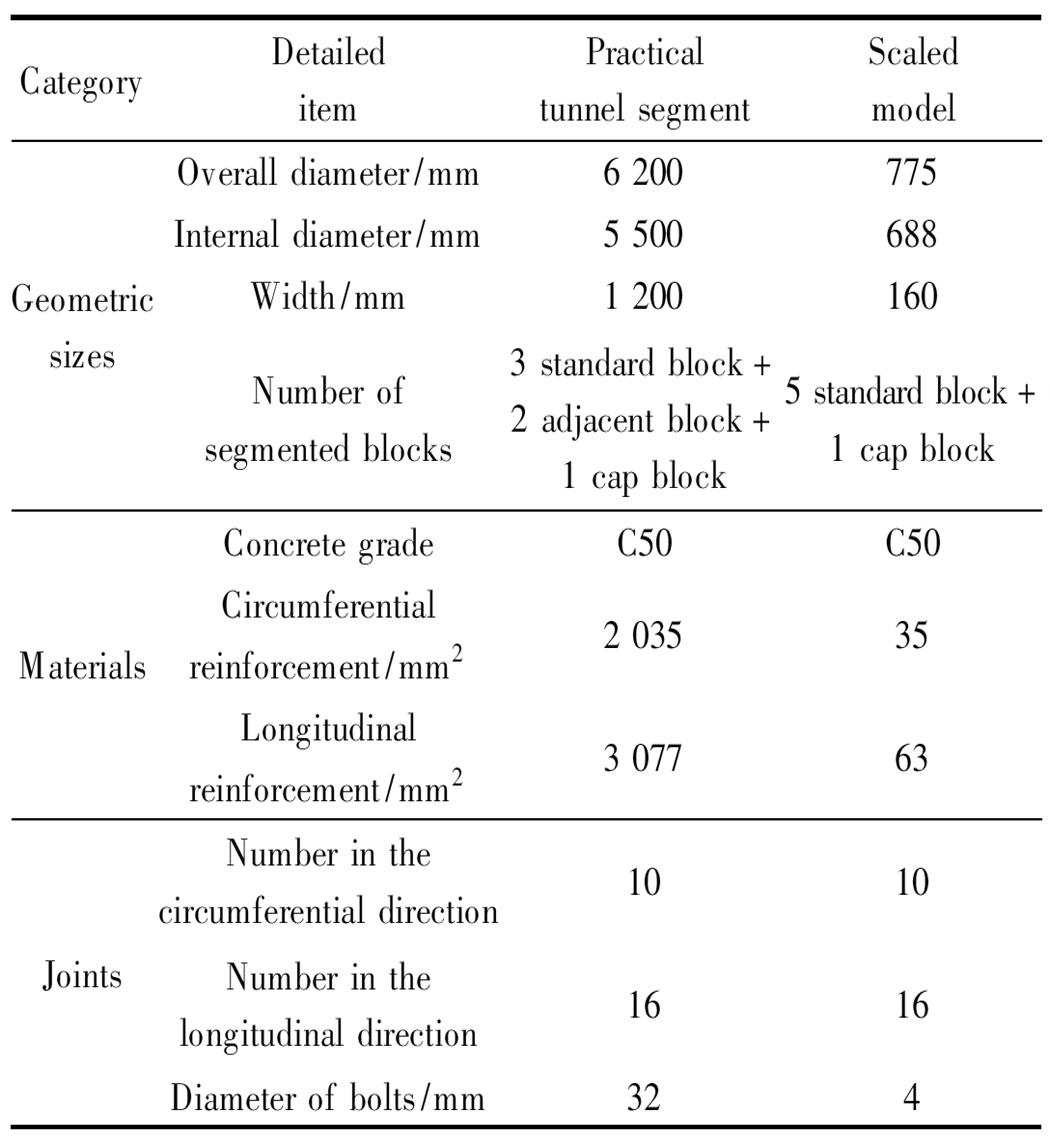
CategoryDetaileditemPracticaltunnelsegmentScaledmodelGeometricsizesOveralldiameter/mm6200775Internaldiameter/mm5500688Width/mm1200160Numberofsegmentedblocks3standardblock+2adjacentblock+1capblock5standardblock+1capblockMaterialsConcretegradeC50C50Circumferentialreinforcement/mm2203535Longitudinalreinforcement/mm2307763JointsNumberinthecircumferentialdirection1010Numberinthelongitudinaldirection1616Diameterofbolts/mm324
Fig.3 shows the simulation of the tunnel’s surrounding conditions. The surrounding soil was silty clay, and the tested modulus of compression was 3 MPa. The thickness of the soil between the ground and the tunnel bottom was 0.3 m, and the total height of the soil was 0.9 m.
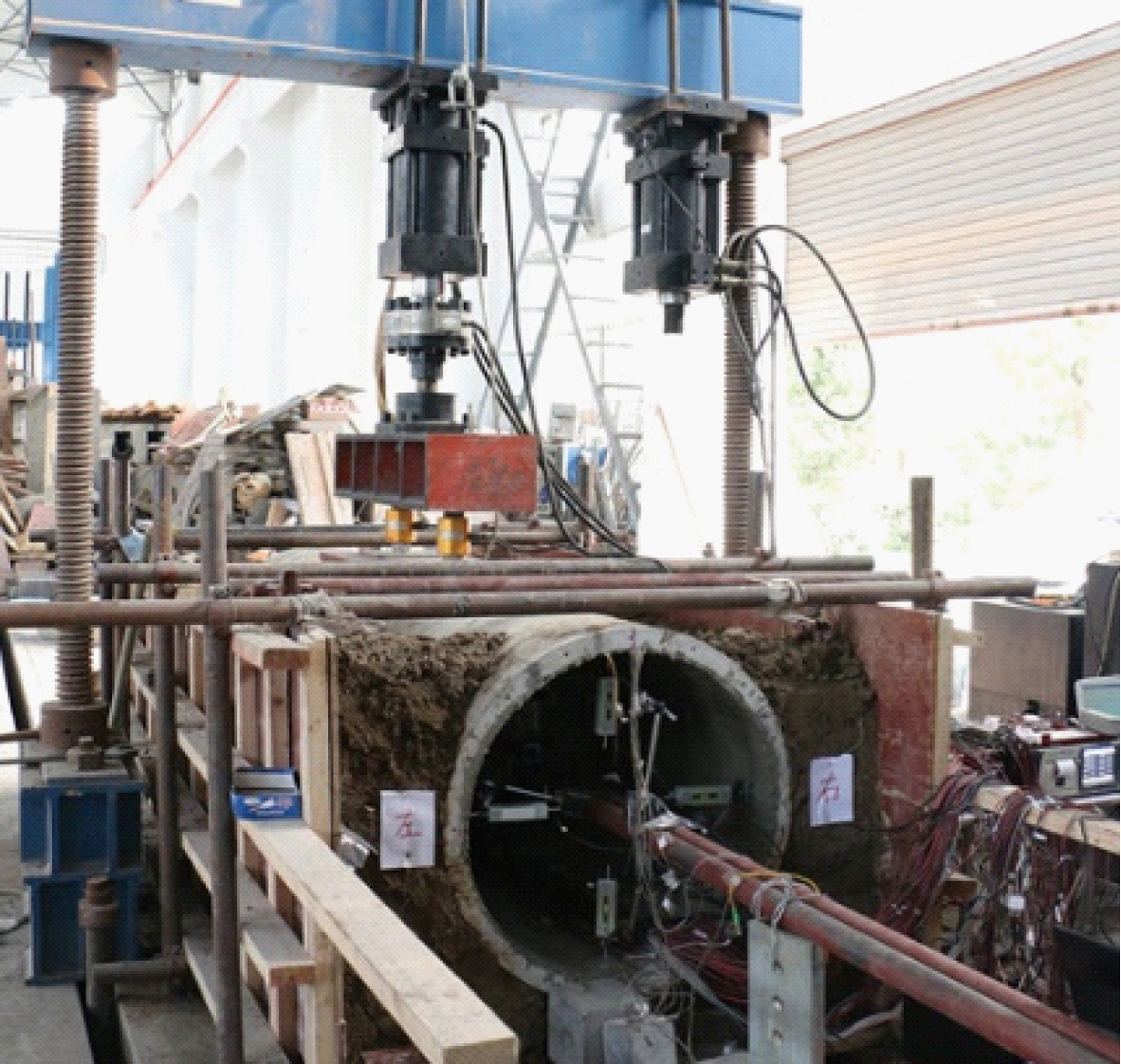
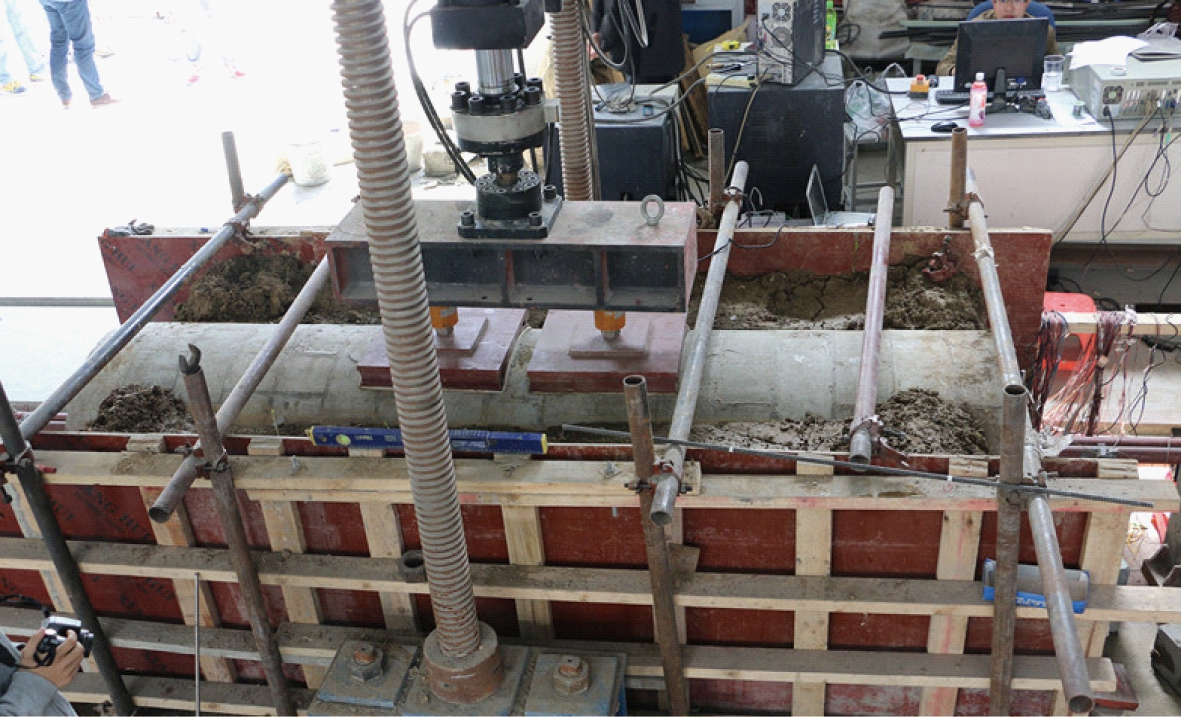
According to the test set-up shown in Fig.4, the load was applied with an MTS loading system. Uniformly distributed loads were applied to the middle six segments for the simulation of a local settlement. As shown in Fig.4(b), for the creation of a uniformly distributed load and also to avoid local shear failure, arc steel plates with a width of 380 mm were placed between the load sensor and tunnel segments. In addition, rubber blankets with a thickness of 10 mm were placed between the arc steel plates and the tunnel segments. A displacement control mode was adopted as the load method in this experiment. There was a total of 108 load steps, with a step size of 0.5 mm. For the first 70 steps, the 71th to 90th step, and the 91th step to the end, the loading rates were 0.5, 1, and 2 mm/min, respectively.
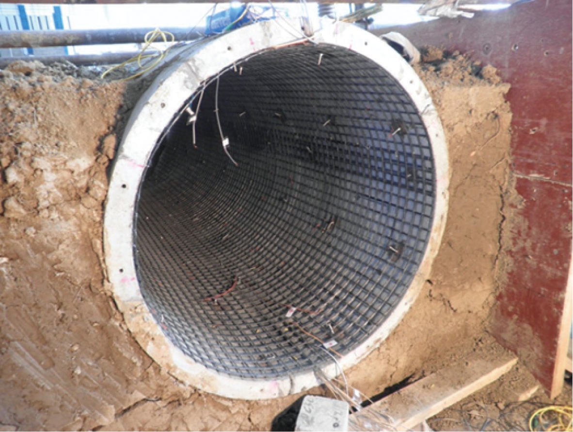
Fig.3 The scaled tunnel mode with the CFRP grid placed inside in the laboratory
(a)
(b)
Fig.4 Test set-up. (a) Side view; (b) Top view
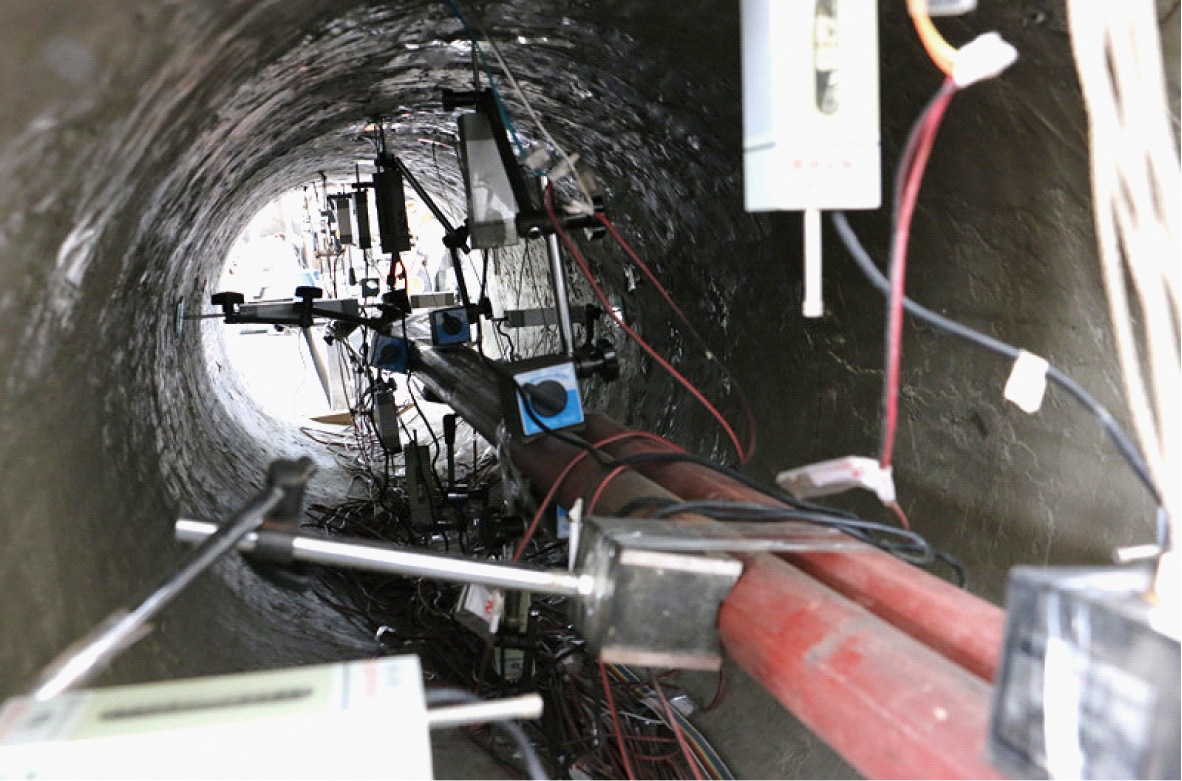
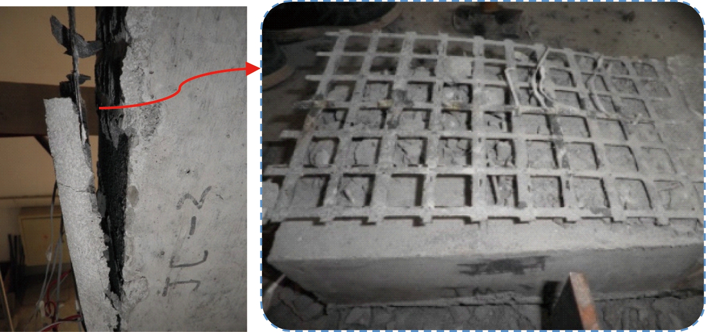
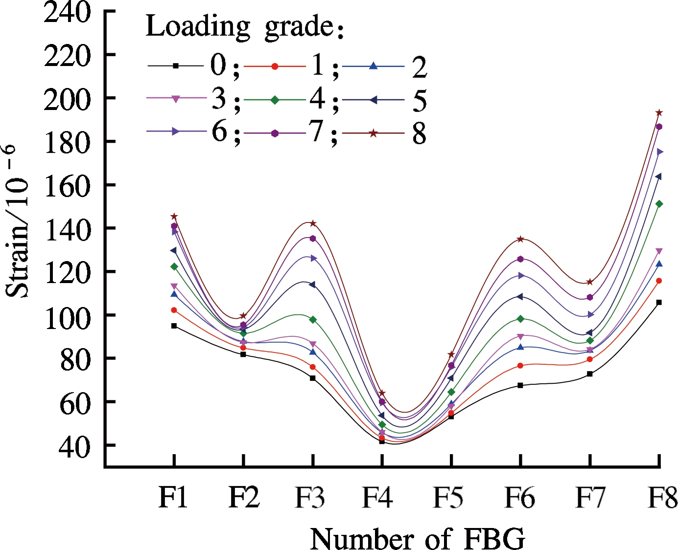
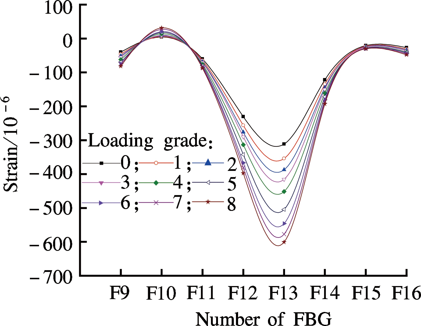
As shown in Fig.5(a), the tunnel model was divided into 16 elements, named E1 to E16 one by one, with each element comprised of two half tunnel segments and one circumferential joint and the 1st and the 17th half segment was not considered. Since the damage at the middle eight elements, i.e., E5 to E12, should be much more serious than that at the two end parts, sixteen fiber bragg grating (FBG) sensors were longitudinally attached to the bottom and top concrete walls inside the tunnel. FBG sensors could monitor the overall longitudinal strains along the bottom and top concrete walls. These FBG sensors were named F1 to F16 one by one. Regarding the monitoring of the displacements, the displacements at the top, bottom, and lateral walls were tested using linear variable differential transformers (LVDTs). The positions of the LVDTs are shown in Fig.5(a), and Fig.5(b) shows the inside photograph of the tunnel with the LVDTs placed. The top and bottom displacements at the 1st, 5th, 9th, 13th, and 17th segments were tested, and the lateral displacements at the 1st, 9th, and 17th segments were tested.

(a)
(b)
Fig.5 The positions of LVDTs and FBGs. (a) Schematic diagram; (b) Inside photograph
2.1 Failure modes and ultimate loads
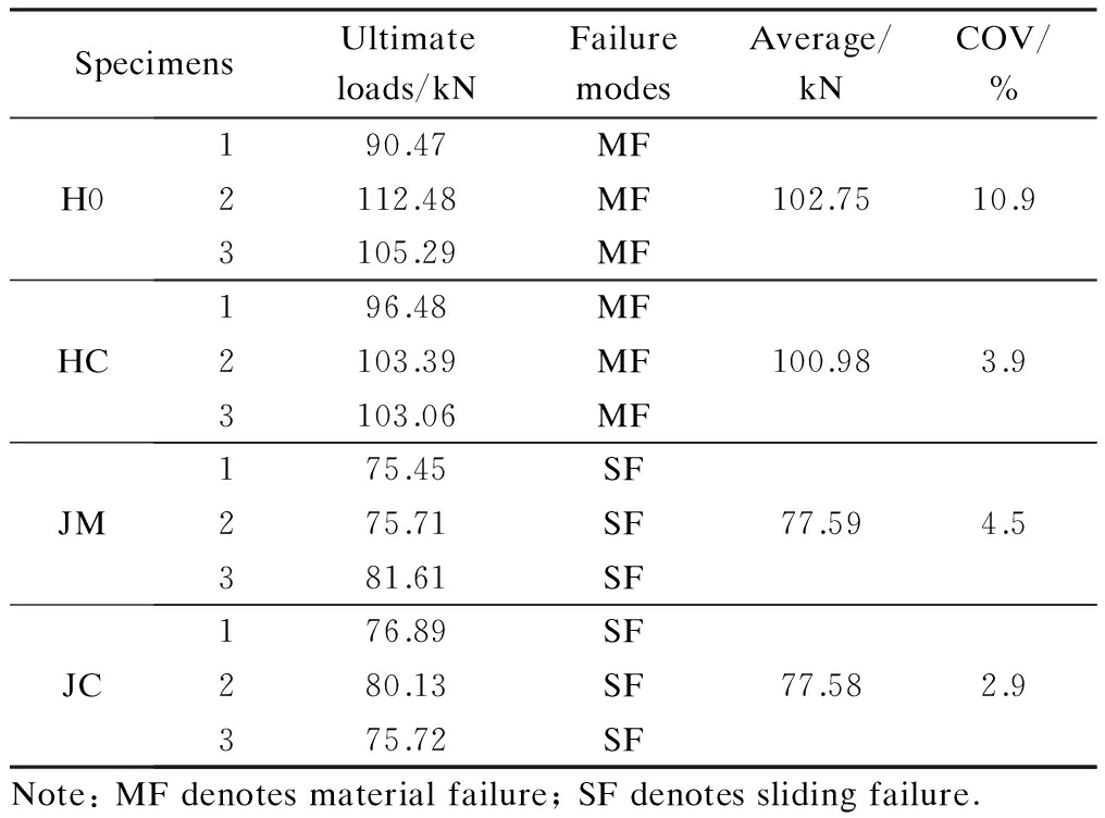
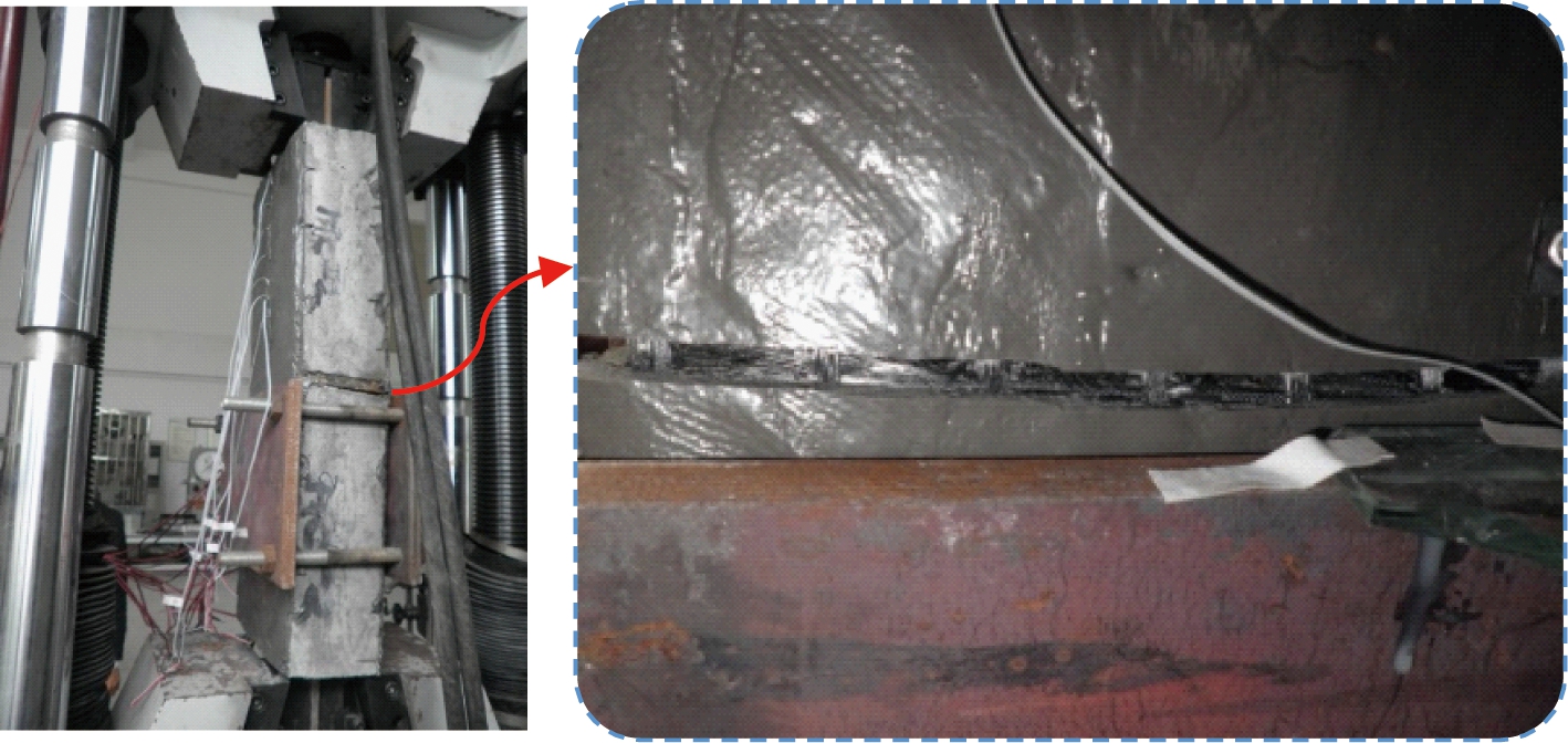
The test results of the 12 double-shear bond specimens are listed in Tab.4, and their typical bond failure modes are shown in Fig.6. As shown in Figs.6(a) and (b), the specimens with epoxy structural adhesive both failed because the CFRP ruptured, and almost no slips were observed. With the increase of the load, the structural adhesive first cracked at one side, and then small sounds of fiber rupture were heard. As the load continued to increase, the structural adhesive at the other side also cracked, and an increasing number of sounds of fiber rupture was heard. Finally, the CFRP grids near the wood separator ruptured. For the HC group with grooves on the concrete surface, oblique cracks of 45° on the concrete near the crack of structural adhesive were observed, indicating the good bond performance between the structural adhesive and the concrete substrate. The ultimate loads of the H0 and HC groups were similar, indicating that the surface treatment with grooves was unnecessary when the structural adhesive was used.
Tab.5 Double-shear bond test results
SpecimensUltimateloads/kNFailuremodesAverage/kNCOV/%H0190.47MF2112.48MF102.7510.93105.29MFHC196.48MF2103.39MF100.983.93103.06MFJM175.45SF275.71SF77.594.5381.61SFJC176.89SF280.13SF77.582.9375.72SFNote:MFdenotesmaterialfailure;SFdenotesslidingfailure.
 (a)
(a)
(b)
(c)
(d)
Fig.6 Typical bond failure modes for the double-shear tests. (a) H0; (b) HC; (c) JM; (d) JC
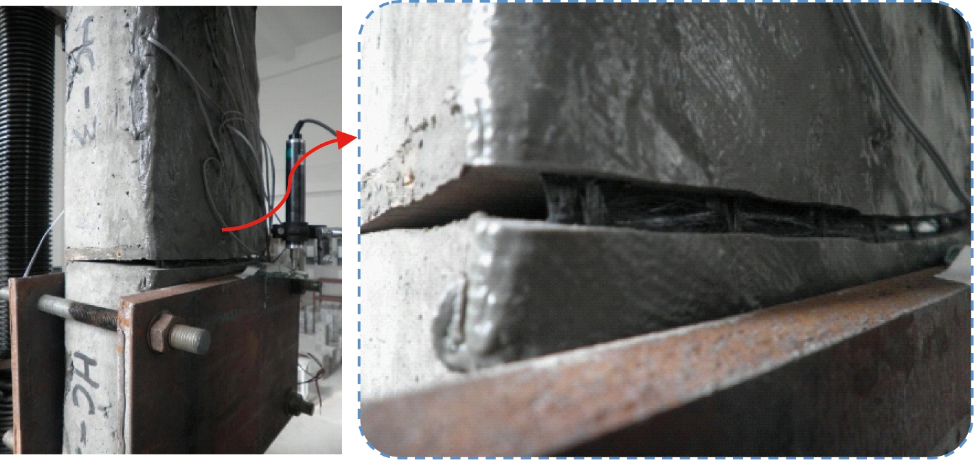
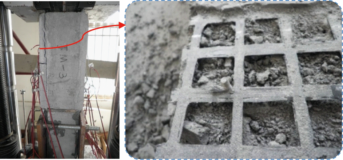
As shown in Figs.6(c) and (d), the inner CFRP grids of specimens with polymer mortar as adhesive did not rupture, and the mortar layer peeled off from the concrete substrate. For the JM group, as shown in Fig.6(c), the anchored bolts provided an out-of-plane constraint on the CFRP grids, and the mortar did not obviously fall off. The local fiber rupture observed on the CFRP grid near the bolts was due to the shear force. However, it did not influence the overall bond performance. For the JC group shown in Fig.6(d), the mortar in grooves served as shear connectors, and they were sheared-off after the test. Since there were no out-of-plane constraints, the mortar obviously fell off from the concrete substrate, and the CFRP grid was pulled out. Similar to the groups with epoxy structural adhesive, the ultimate loads of JC and JM group were similar, but they were obviously lower than those of the H0 and HC groups.
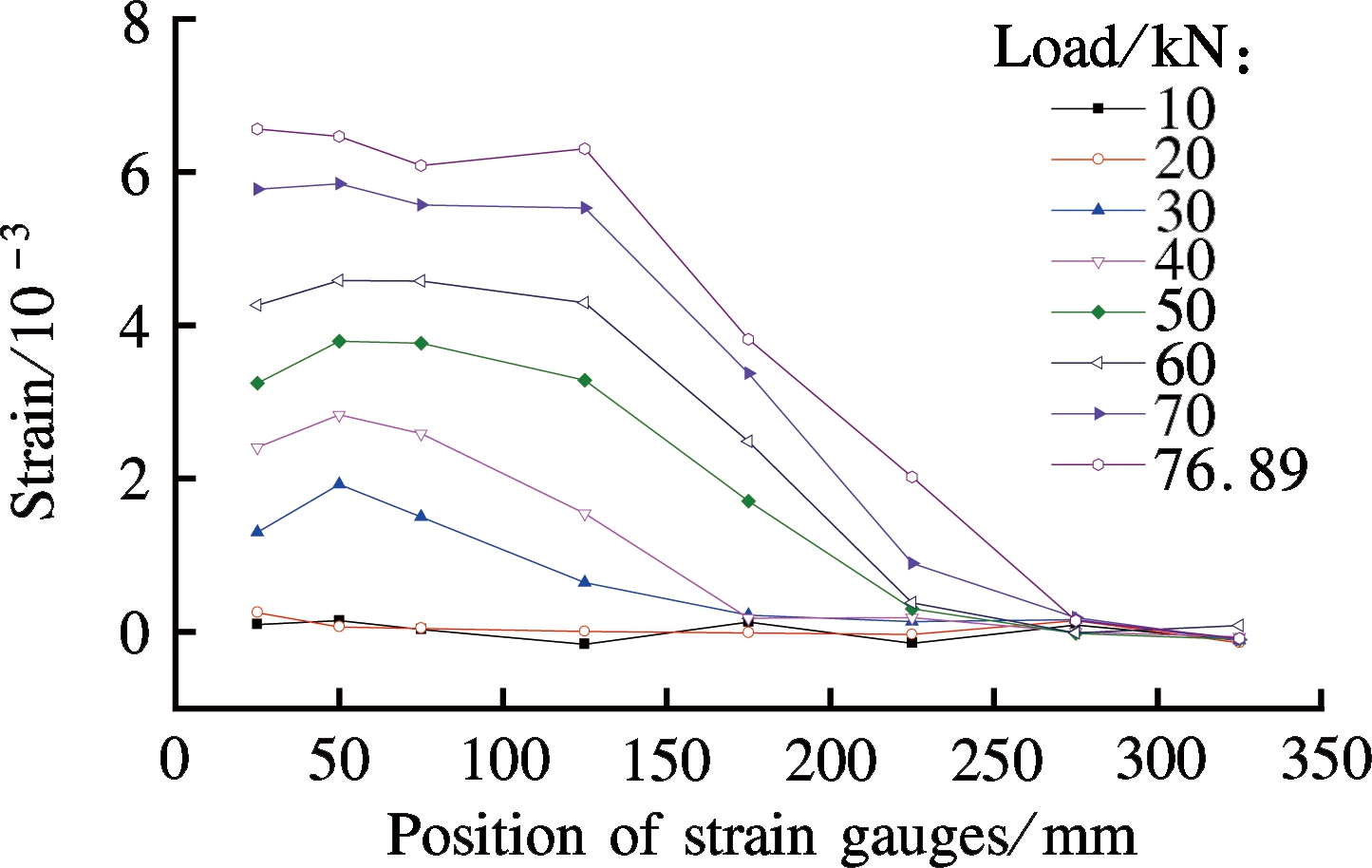
2.2 Strain distribution at CFRP grids
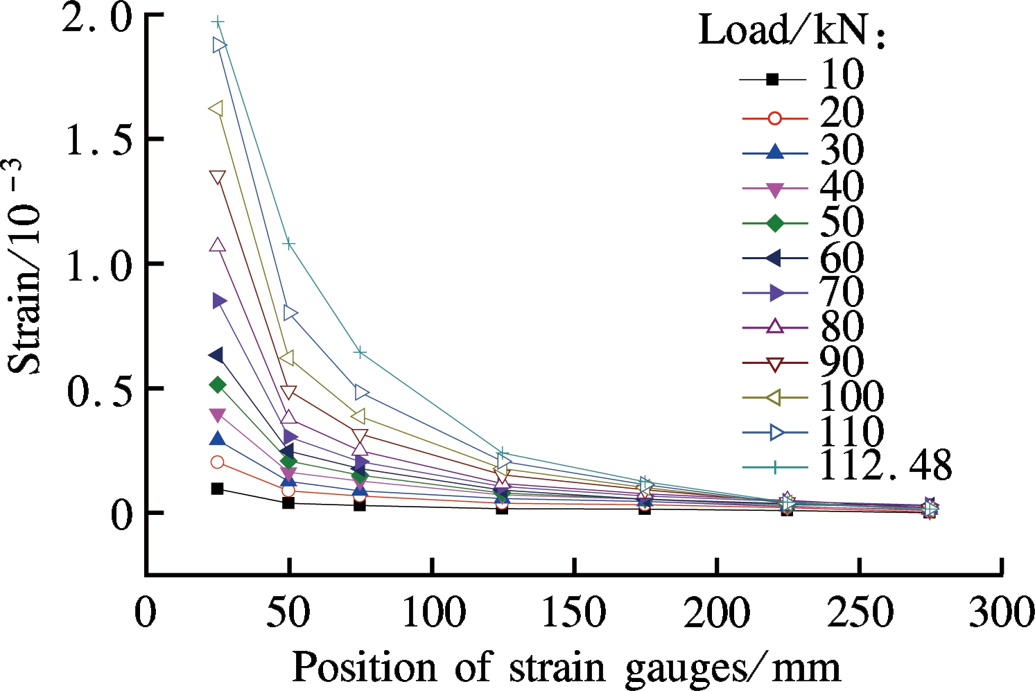
Fig.7 shows the tested strain values of CFRP grids under different load levels; the horizontal axis here represents the distance between the strain gauges and the wood separator (as shown in Fig.2). Figs.7(a) and (b) show the results of the H0 and HC groups with epoxy structural adhesive. The strains close to the pull end were found to be large with the values decreasing rapidly with the increase in the distances. The bond strength transfer lengths were approximately 250 mm for both the H0 and HC groups. By comparing Fig.7(a) and Fig.7(b), the CFRP strains of the HC group with grooves at concrete substrate were found to decrease much more rapidly than that of the H0 group due to the shear resistance of adhesive inside the grooves.
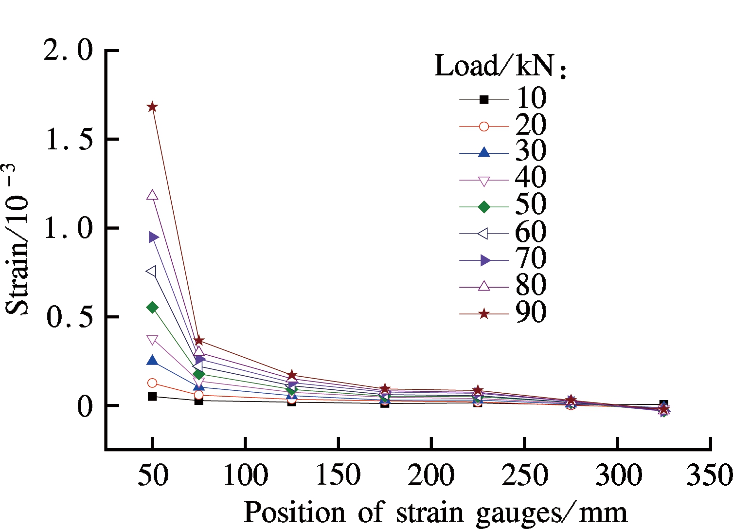
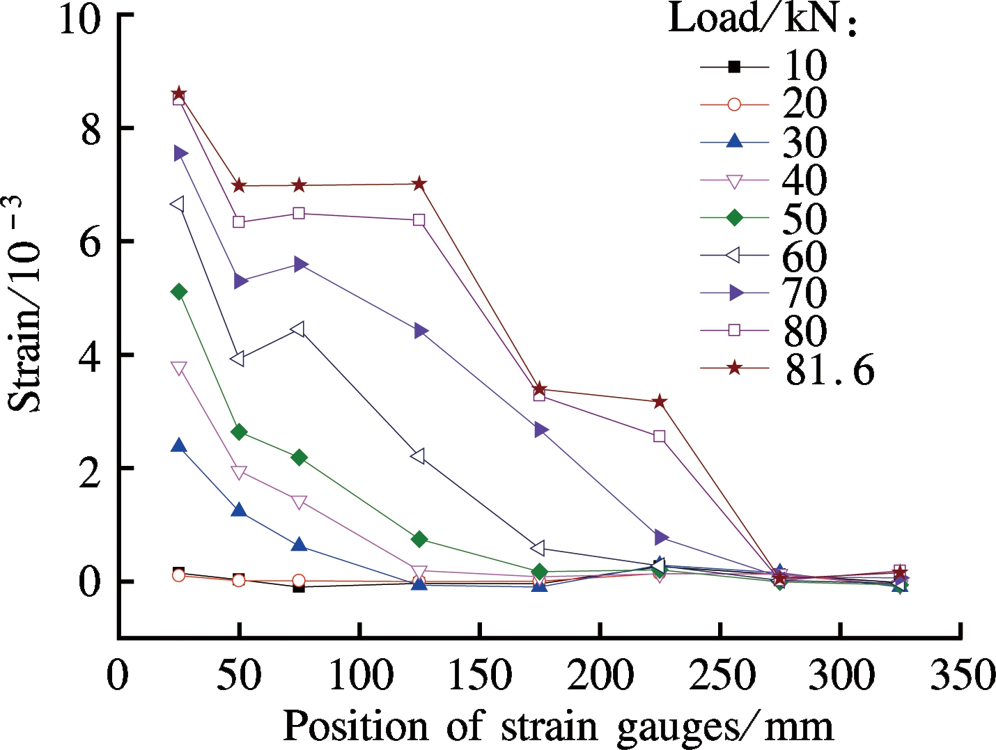
Figs.7(c) and (d) show the results of the JM and JC groups with polymer mortar. The strain values were found to be obviously higher than those of the specimens with structural adhesive due to a weaker bond effect. For the JM group with anchored bolts, the strains decreased with the increase of distances as well, but the speed was obviously lower than the specimens with structural adhesive. For the JC group with grooves in the concrete substrate, in the first 150 mm length of the bond area, the strain values were basically the same; with the further increase of the length, the strains suddenly decreased.
3.1 Load vs. relative displacement curves
Considering the influence of compressive deformations of the surrounding soils, the analysis is based on the difference between the displacement tested by the top LVDT and that of the bottom LVDT. The difference value was defined as the relative displacement. Fig.8 shows the load vs. relative displacement curves of the undamaged and strengthened tunnel at the middle span. Note that the loading of the undamaged tunnel was stopped when the crack widths reached the value the code prescribed. At that point, the load value was 165.68 kN, and the relative displacement was 6.89 mm. Next, the pre-damaged tunnel model was unloaded and strengthened with CFRP grids and epoxy structural adhesive. The strengthened tunnel was then tested until the load capacity obviously decreased.
(a)
(b)
(c)
(d)
Fig.7 CFRP strain distribution along the longitudinal direction. (a) H0; (b) HC; (c) JM; (d) JC
As shown in Fig.9, when comparing the theoretical reload path of the pre-damaged tunnel with the strengthened curve, both the stiffness and strength of the strengthened tunnel were found to be significantly improved. Within the initial 0 to 2.5 mm relative displacement, the load capacity of the strengthened tunnel was still slightly lower than that under the undamaged condition because the tunnel was pre-damaged. With the increase of deformation, the utilization rate of the CFRP grids improved, and the load capacity of the strengthened tunnel was higher than that of the undamaged tunnel. The load capacity of the strengthened tunnel was found to be increased by 19.2% at the loading stopping point of the undamaged tunnel. However, we should also be aware of the excessive positive effect of the epoxy structural adhesive on the improvement of the stiffness because the practical adhesive layer will be very thick after multiplying it by the scaled ratio, which is unrealistic.
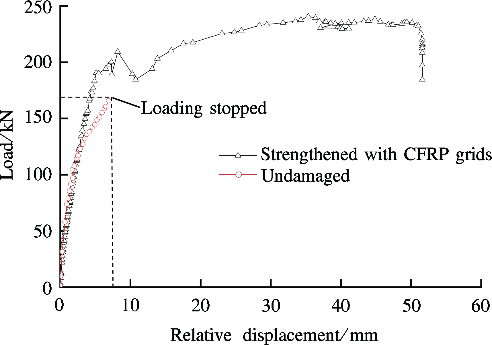
Fig.8 Load vs. relative displacement curves of the scaled tunnel mode at the middle span
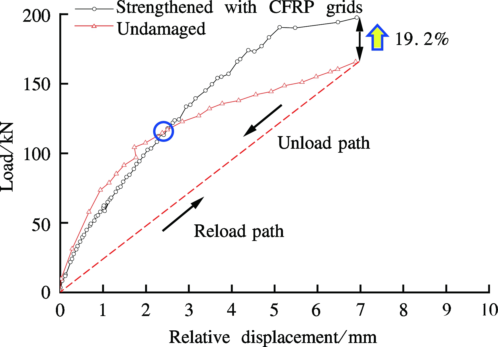
Fig.9 Comparison of the load-relative displacement curve of the undamaged tunnel and the strengthened tunnel within the same range of relative displacements
3.2 Strain distributions tested by FBG sensors
The eight loading grades as listed in Tab.6 were adopted in the analysis of the strain distribution tested by the FBG sensors. The results are shown in Fig.10. The two loading arc plates were located at the E6-E8 and E9-E11 segments, as shown in Fig.5. As shown in Fig.10(a), the strain values measured by F3 and F6 (located under the loading points) were obviously higher than those measured by F4 and F5 due to a higher base settlement. The strain distribution curves were saddle-shaped, in good agreement with the theoretical results based on the elastic foundation beam theory. As shown in Fig.10(b), for the strains at the top section, the compressive strains mainly appeared at the loading area, i.e., the F10 to F15 area. The tested strain distributions at the top section met the actual loading condition. The observed crack damage was due to pre-loading at the joint of tunnel segments that the F4 FBG crossed. However, after strengthening with CFRP grids, the strains at F4 FBG remained at small values because the tunnel segments were further connected as a whole by the CFRP grid layer, thereby improving the overall performance.
Tab.6 The eight loading grades adopted in the analysis
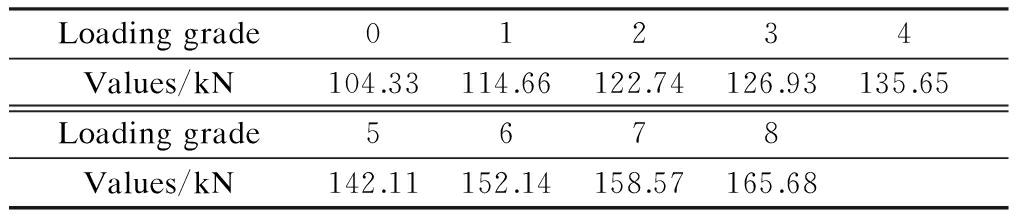
Loadinggrade01234Values/kN104.33114.66122.74126.93135.65Loadinggrade5678Values/kN142.11152.14158.57165.68
(a)
(b)
Fig.10 Tested strains by the FBGs. (a) Bottom section; (b) Top section
1) For the double-shear bond specimens, when the adhesive was epoxy structural adhesive, the failure mode was the rupturing of the CFRP grids. When the polymer mortar was used as an adhesive, the failure mode was sliding failure, and the CFRP grids did not rupture.
2) The surface treatment with grooves was unnecessary when the structural adhesive was used. For the bond specimens using polymer mortar, the anchored bolts provided an out-of-plane constraint on the CFRP grid, and the mortar did not obviously fall off. In contrast, the mortar obviously fell off from the concrete substrate, and the CFRP grid was removed for specimens with surface grooves.
3) For the strengthened tunnel, with the increase of deformation, the utilization rate of the CFRP grids improved, and the load capacity of the strengthened tunnel was higher than that of the undamaged tunnel.
4) The tunnel segments were further connected as a whole by the CFRP grid layer, and the overall performance of the tunnel was improved.
[1]Teng J G. FRP strengthened RC structures [M]. Beijing: China Building Industry Press, 2005. (in Chinese)
[2]Banthia N, Al-Asaly M, Ma S. Behavior of concrete slabs reinforced with fiber-reinforced plastic grid [J]. Journal of Materials in Civil Engineering, 1995, 7(4): 252-257. DOI:10.1061/(asce)0899-1561(1995)7:4(252).
[3]Matthys S, Taerwe L. Concrete slabs reinforced with FRP grids. Ⅰ: One-way bending [J]. Journal of Composites for Construction, 2000, 4(3): 145-153. DOI:10.1061/(asce)1090-0268(2000)4:3(145).
[4]Matthys S, Taerwe L. Concrete slabs reinforced with FRP grids. Ⅱ: Punching resistance [J]. Journal of Composites for Construction, 2000, 4(3): 154-161. DOI:10.1061/(asce)1090-0268(2000)4:3(154).
[5]Yost J R, Goodspeed C H, Schmeckpeper E R. Flexural performance of concrete beams reinforced with FRP grids [J]. Journal of Composites for Construction, 2001, 5(1): 18-25. DOI:10.1061/(asce)1090-0268(2001)5:1(18).
[6]Rahman A H, Kingsley C Y, Kobayashi K. Service and ultimate load behavior of bridge deck reinforced with carbon FRP grid [J]. Journal of Composites for Construction, 2000, 4(1): 16-23. DOI:10.1061/(asce)1090-0268(2000)4:1(16).
[7]Wu G, Wu Z S, Jiang J B, et al. A new technology of strengthening concrete structures with FRP grids and its application [J]. Const Tech, 2007, 36(12): 98-102. (in Chinese)
[8]Zheng Y Z, Wang W W, Brigham J C. Flexural behaviour of reinforced concrete beams strengthened with a composite reinforcement layer: BFRP grid and ECC [J]. Construction and Building Materials, 2016, 115: 424-437. DOI:10.1016/j.conbuildmat.2016.04.038.
[9]Papanicolaou C, Triantafillou T, Lekka M. Externally bonded grids as strengthening and seismic retrofitting materials of masonry panels [J]. Construction and Building Materials, 2011, 25(2): 504-514. DOI:10.1016/j.conbuildmat.2010.07.018.
[10]Corradi M, Borri A, Castori G, et al. Shear strengthening of wall panels through jacketing with cement mortar reinforced by GFRP grids[J]. Composites Part B: Engineering, 2014, 64: 33-42. DOI:10.1016/j.compositesb.2014.03.022.
[11]Wu G, Wu Z S, Luo Y B, et al. Aseismic performance of circular concrete columns confined with FRP grids [J]. Journal of Architecture and Civil Engineering, 2007, 24(4): 39-44. (in Chinese)
[12]Bentayeb F, Tahar K A, Chateauneuf A. New technique for reinforcement of concrete columns confined by embedded composite grid [J]. Construction and Building Materials, 2008, 22(8): 1624-1633. DOI:10.1016/j.conbuildmat.2007.06.015.
[13]Shi J W, Zhu H, Wu Z S, et al. Experimental study on bond behavior between basalt/hybrid FRP sheets and concrete substrates [J]. Journal of Southeast University: Natural Science Edition, 2010, 40(3): 554-558. (in Chinese)
[14]Shen S. Development of structural health monitoring system for underground tunnel based on the distributed fiber optic sensing technique [D]. Nanjing: School of Civil Engineering, Southeast University, 2011. (in Chinese)
References:
摘要:对碳纤维增强树脂(CFRP)网格加固受损缩尺盾构隧道模型的有效性进行了试验研究.首先,对CFRP网格与混凝土表面采用不同粘结材料和表面处理方式时的粘结性能进行了研究.采用最有效的锚固方式对随后的缩尺隧道进行了加固.研究结果表明,采用环氧结构胶作为粘结材料时,粘结试验均表现为网格材料破坏,粘结锚固性能最优;而采用聚合物砂浆锚固时,表面锚栓锚固处理和表面开槽处理均能提高粘结性能,破坏模式为聚合物砂浆剥落的滑移破坏.受损隧道模型采用CFRP网格加固后,刚度和承载力都得到了明显提升.此外,FBG的测试结果表明,加固后的隧道环缝应变减小,隧道整体性能得到提升.
关键词:CFRP网格;双面剪切试验;表面处理方式;缩尺隧道模型;相对挠度
中图分类号:TU502
Received:2016-12-10.
Foundation item:s:The Science and Technology Project of China Southern Power Grid Co., Ltd. (No.GDKJ00000030), the National Key Technology R&D Program of China (No.2016YFC0701400), the National Natural Science Foundation of China (No.51525801).
Citation::Li Wensheng, Wu Gang, Dong Zhiqiang, et al. Experimental study on a pre-damaged scaled tunnel model strengthened with CFRP grids[J].Journal of Southeast University (English Edition),2017,33(2):196-202.
DOI:10.3969/j.issn.1003-7985.2017.02.012.
DOI:10.3969/j.issn.1003-7985.2017.02.012
Biographies:Li Wensheng (1984—), male, doctor; Wu Gang (corresponding author), male, professor, g.wu@seu.edu.cn.