Mechanical performance of the mixed post-installed connectionin low-strength concrete
Wang Yongquan1 Chen Tianjiao1 Jing Jian2
(1College of Water Conservancy and Hydropower Engineering, Hohai University, Nanjing 210098, China)(2College of Civil and Transportation Engineering, Hohai University, Nanjing 210098, China)
Abstract:Due to inadequate bearing capacity of the chemically-planted steel bar in low-strength concrete, a new mixed post-installed connection is proposed using small diameter anchoring steel bars and grouting materials together to anchor the main steel bar. To investigate the feasibility of the proposed post-installed connections, a series of pull-out tests with different anchors were conducted for comparison, including fully adhesive anchors, partially adhesive anchors, grouting material anchoring connection and the new mixed post-installed connection. The experimental results of the single steel bar pull-out test show that the mixed post-installed connection can effectively enhance the bearing capacity of post-installed steel bars in low-strength concrete. The bearing capacity is increased by nearly two times with no cone-type concrete failure compared with the fully adhesive anchor. The results show that adopting the new mixed post-installed connection can ensure that joint performance meets the requirements if the space dimension is available.
Key words:low-strength concrete; post-installed connection; chemically-planted steel bars; bearing capacity; failure pattern
Chemically-planted steel bars are widely used in post-installed adhesive anchors[1-2]. Among all the factors that may affect performance of chemically-planted steel bars, the strength of a concrete matrix is the most important. Eligehausen et al.[3] investigated the average bond stress and concrete compressive strength fc of chemically-planted steel bars. The study showed that when the concrete compressive strength fc≥40 MPa, the average bond stress is a constant; when 20 MPa≤fc≤40 MPa, the average bond stress exhibits a linear relationship to the concrete compressive strength; however, when fc≤20 MPa, the relationship was not given. Akiyama et al.[4] conducted studies on the mechanical behavior of chemically-planted steel bars subjected to tension, and compared the load-displacement curves, the distribution of cracks and the ultimate load of chemically-planted steel bars with an embedment depth of seven times the bar diameter in the C5 and C15 concrete matrix. This conclusion indicates that the mechanical behavior of chemically-planted steel bars in C15 concrete is superior to that in C5 (i.e., the ultimate bearing capacity increases by nearly 1 times), and its ability to absorb energy is clearly enhanced while the crack width visibly decreases. Maz lgüney[5] conducted experimental studies on old framed structures (The compressive strength of concrete was in the range of 6.2 to 17.5 MPa). The results indicate that concrete strength has minor effect on the bearing capacity of chemically-planted steel bars. Besides, according to the theoretical calculation and experimental contrast, the average shear stress model is applicable to the calculation of the bonding capacity of the chemically-planted steel bars in low-strength concrete, but the average bonding strength must be determined through pull-out tests.
Although much research has been done on the mechanical performance of chemically-planted steel bars in low-strength concrete, design methods for chemically-planted steel bars in low-strength concrete are divergent. Moreover, single reinforcement pull-out test results show that increasing the anchoring depth of chemically-planted steel bars in low-strength concrete is unable to prevent local cone-type concrete failure. Therefore, in this paper, a new mixed post-installed connection is proposed considering the application in low-strength concrete to ensure joints’ connection performance and to solve local cone-type concrete failure problem.
1 Connection Design
When the chemically-planted steel bar is fully anchored into low-strength concrete, low concrete strength will cause local cone-type concrete failure in the early stage of load applying during the single reinforcement pull-out test. The local failure leads to the decrease of the bearing capacity of the pull-out anchor system or to interfacial bonding failure. According to the stress-transfer mechanism of chemically-planted steel bars[1-3] at the elastic stage, the interfacial bonding stress is not distributed along the bonded length, but declines exponentially in the direction of the depth. Therefore, in view of the mechanical characteristics and failure pattern of chemical adhesive steel bars, comparison research, involving four types of post-installed anchors[6-8], is carried out to improve the mechanical performance of a single anchor in low-strength concrete.
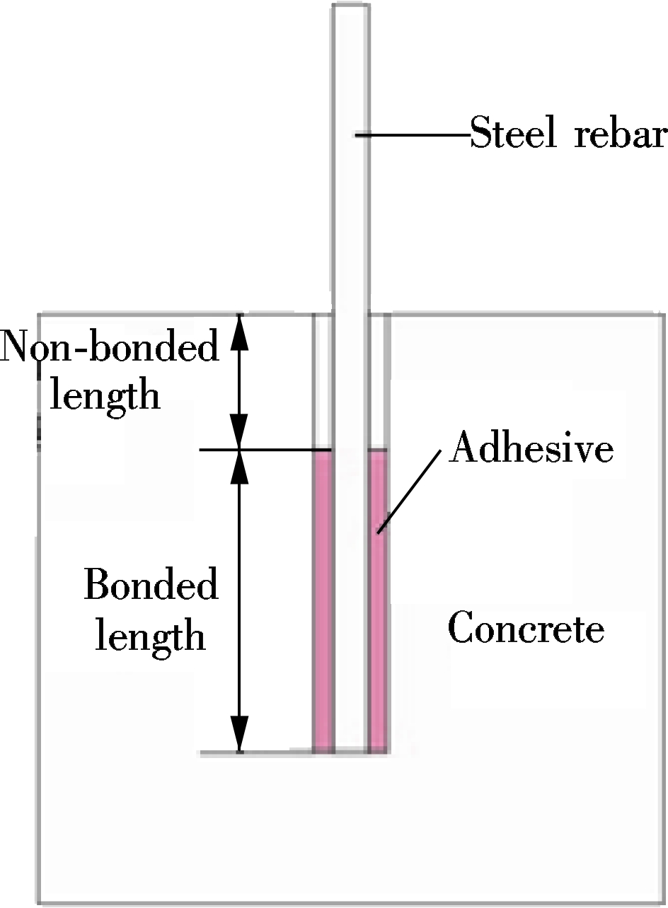
1.1 Fully bonded anchor
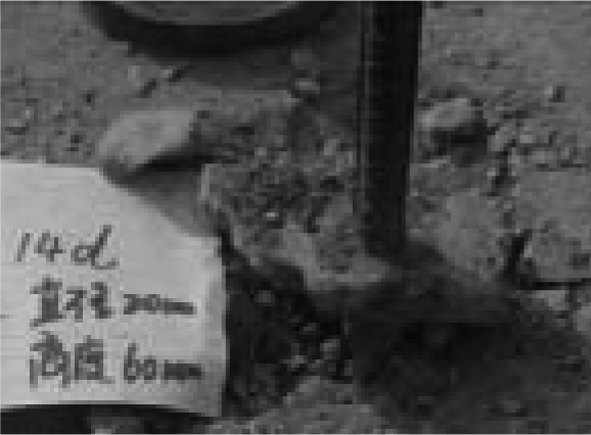
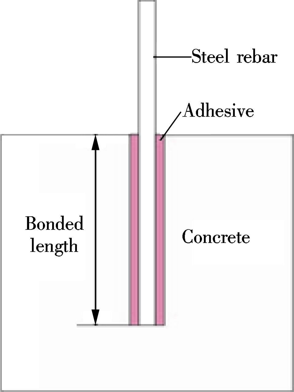
The main difference was that the fully bonded anchors were designed first according to the connection of adhesive anchors in a high-strength concrete matrix. These anchors were bonded to the concrete all along their embedment length by a chemical adhesive[9]. As shown in Fig.1, the bonded lengths were 7, 10 and 14 times the steel rebar diameter.
1.2 Partially bonded anchor
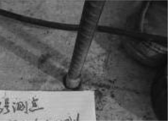
Partially bonded anchors with chemical adhesives were designed for a low-strength concrete matrix[10](see Fig.2). This connection structure was supposed to avoid premature cone concrete failure and improve the single reinforcement pull-out capacity. The embedment lengths for partially bonded anchors were 7, 10 and 14 times the steel rebar diameter, and non-bonded length were 3 and 4 times, while bonded length were 4, 7 and 10 times, respectively.
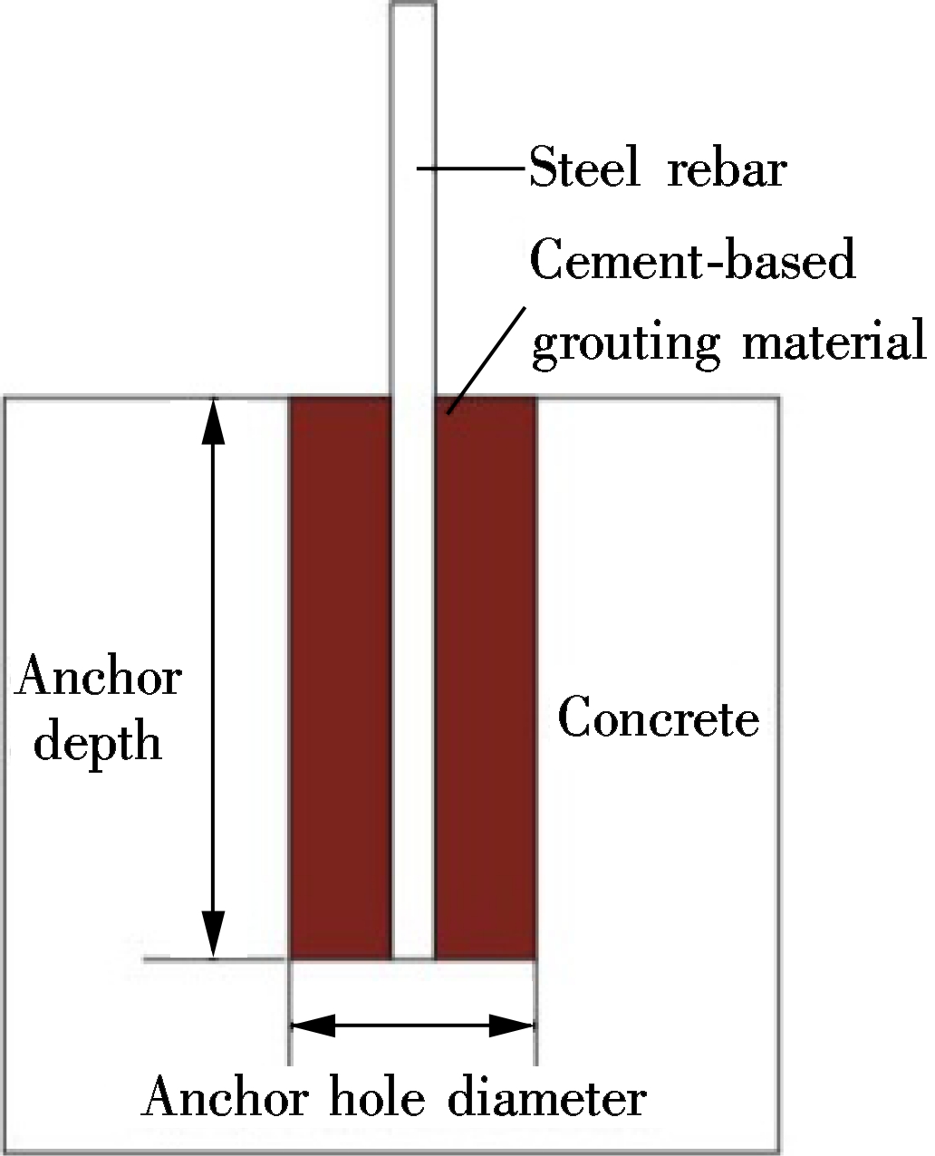
1.3 Cement-based grouting material anchor
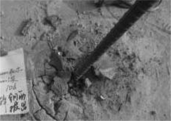
As noted by Cook et al.[1], the carrying capacity of chemically-planted steel bars was correlated to the concrete strength, thus high-strength cement-based grouting material were designed to replace local low-strength concrete[11] (see Fig.3). In the post-installed connection, a post-installed steel rebar was inserted into a drilled hole in the low-strength concrete matrix, and the high-strength cement-based grouting material acted as a bonding agent between the concrete and the steel rebar. The diameter of the anchor hole was 100 mm, while the anchoring depth were 7 and 10 times the steel rebar diameter.
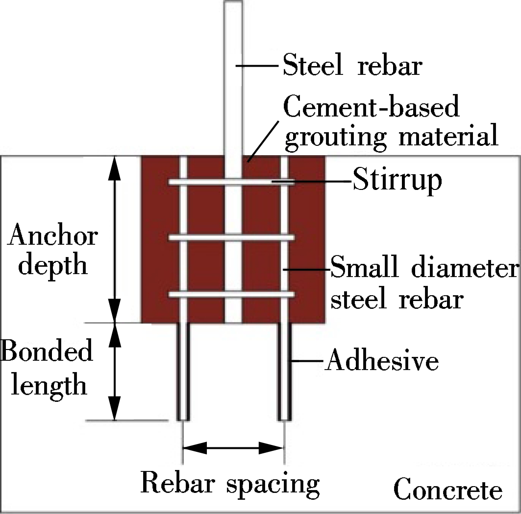
1.4 Mixed post-installed connection
A new mixed post-installed connection using a small diameter anchoring steel bar and cement-based grouting material was proposed considering the advantages and disadvantages of the above connection structures (see Fig.4). The specific practice of the mixed connection structure was applied as follows: First, a concrete cylinder was drilled out from the low-strength concrete. Secondly, small diameter steel bars were anchored at the bottom of the hole using the chemical anchorage method. Thirdly, stirrups were arranged for the small diameter steel bars, and finally, a post-installed steel rebar was installed. The cement-based grouting material was cast as well. It is noteworthy that in order to improve the pull-out capacity of single reinforcement, some small diameter reinforcing rebars and a post-installed anchoring bar were lapped to work together in the grouting region.
2 Mechanical Performances of Different Connections
In order to validate whether the new mixed connection can suffice the post-installed anchor system in mechanical performance, the pull-out experiments are conducted on the aforementioned four types of connection structures. From the experimental results, the peak loads of different connections are obtained and the failure modes are described.
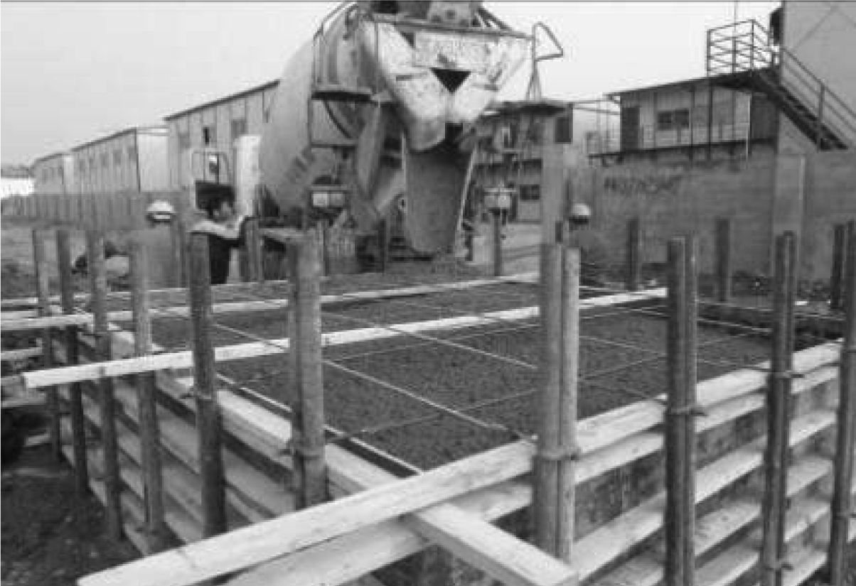
2.1 Concrete matrix and post-installed anchoring bar
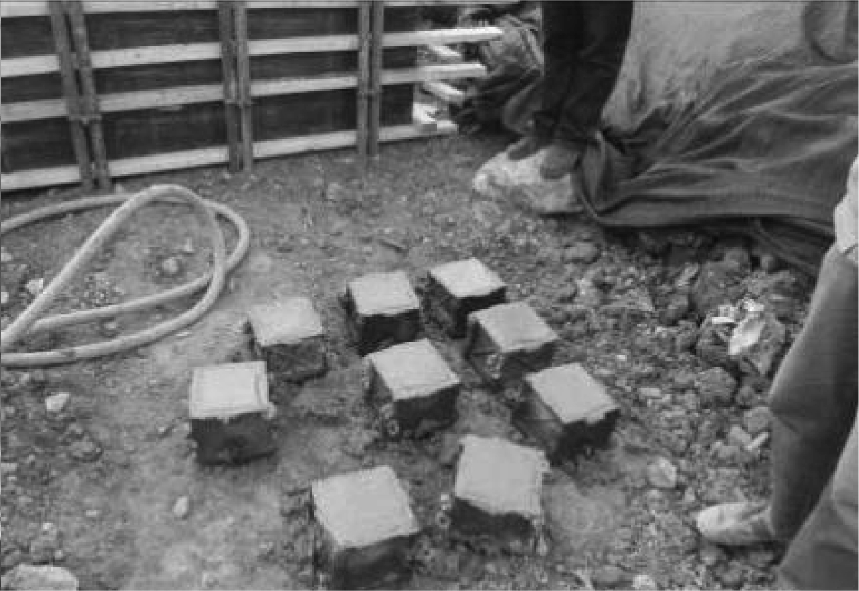
The plain concrete matrix with a dimension of 3 000 mm×4 000 mm×1 000 mm is employed in the test, along with the measured compressive strength of which is 7.3 MPa. The post-installed rebar with the diameter of 16 mm is adopted with the yield strength and the ultimate strength of 400 and 540 MPa, respectively. The yield load of the reinforcement is 80.44 kN, and the ultimate load is 108.59 kN. The casting of the low-strength concrete matrix is shown in Fig.5(a),and the concrete cubes for testing compressive strength are shown in Fig.5(b).
2.2 Production of different specimens
According to the design of the connections, three specimens are fabricated for each connection. The diameter of each steel rebar is 16 mm, and the specific connection design is shown in Tab.1.
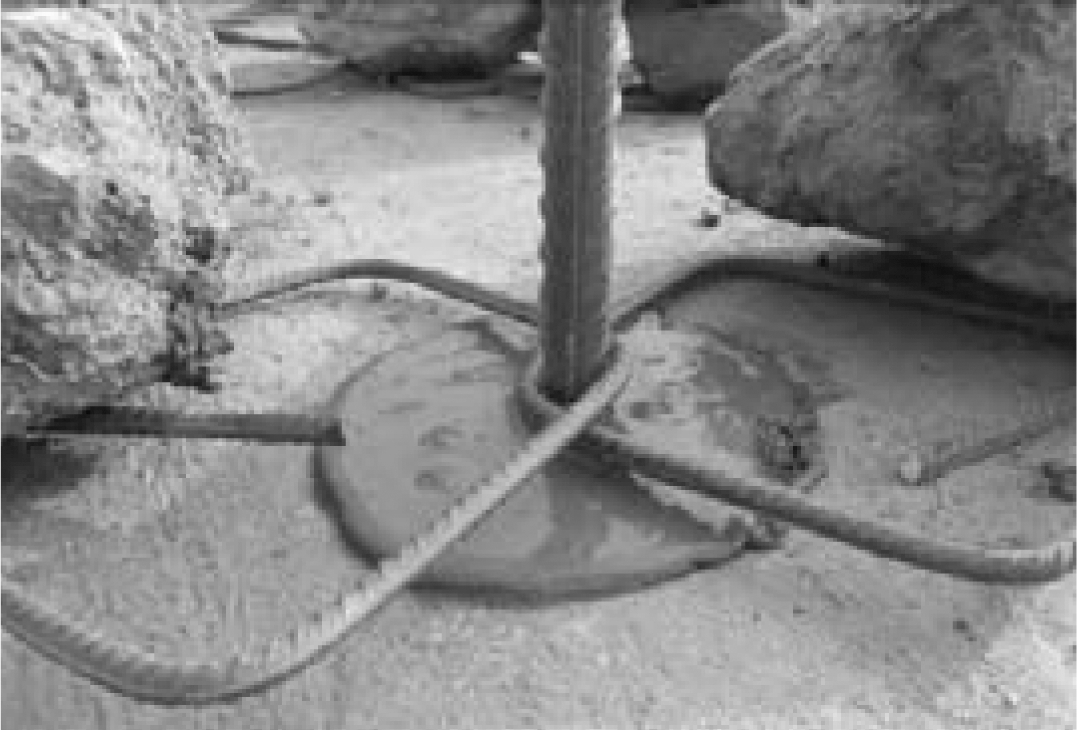
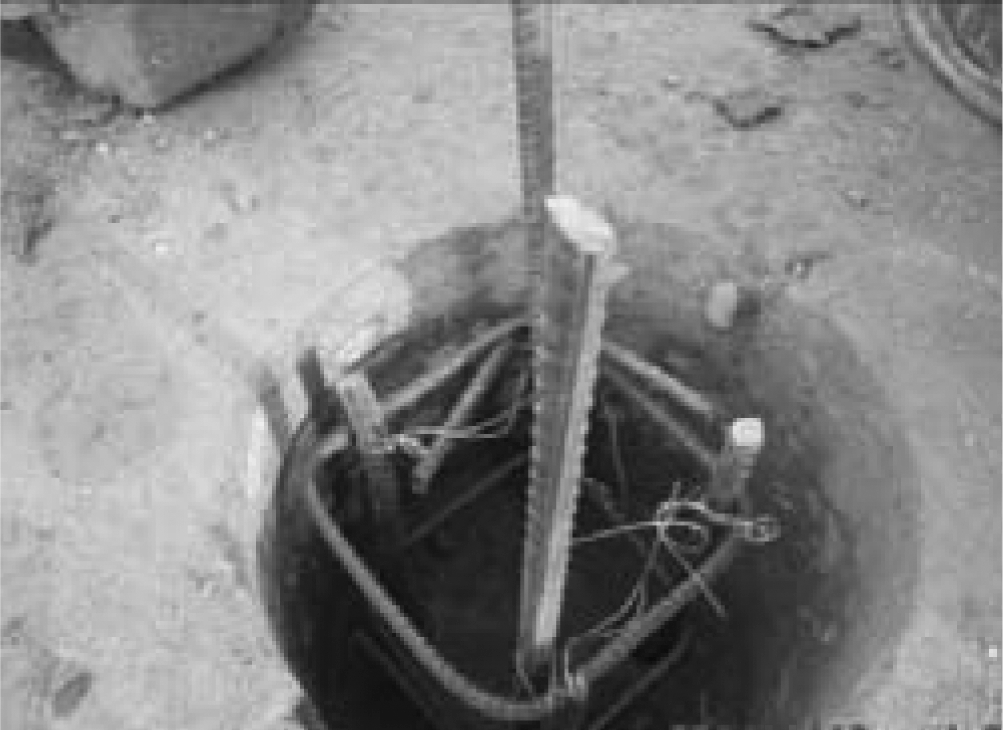
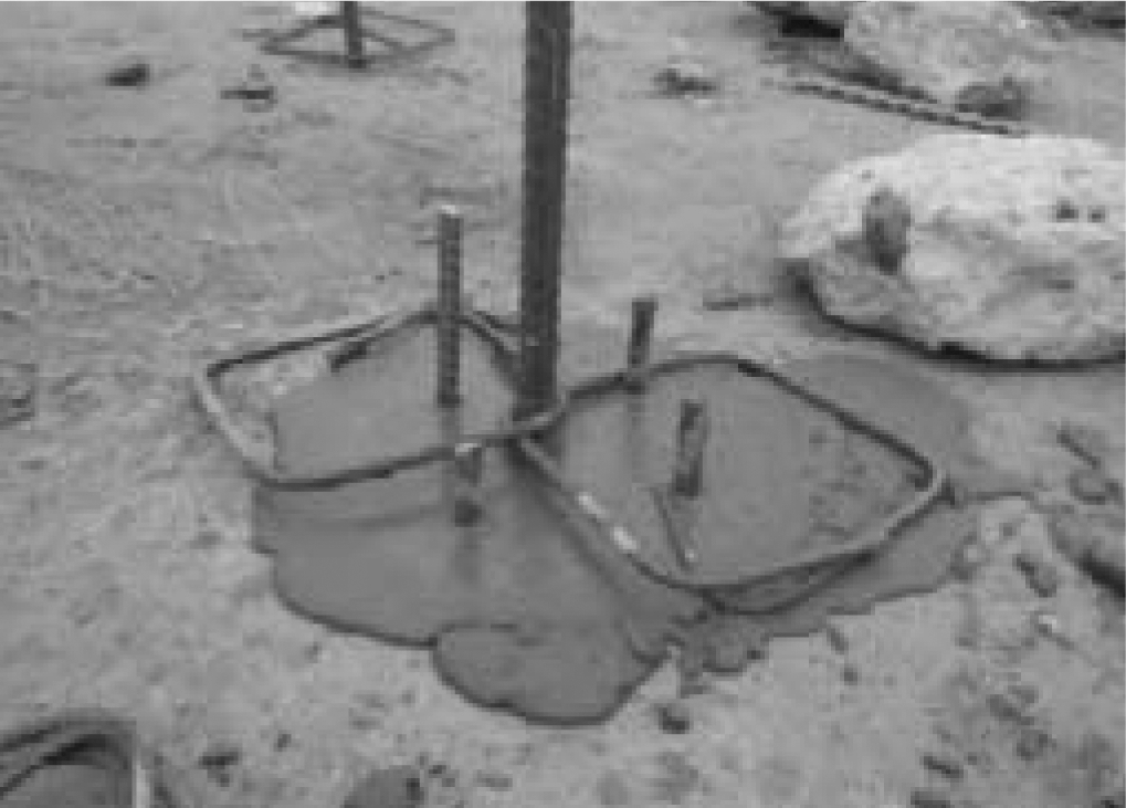
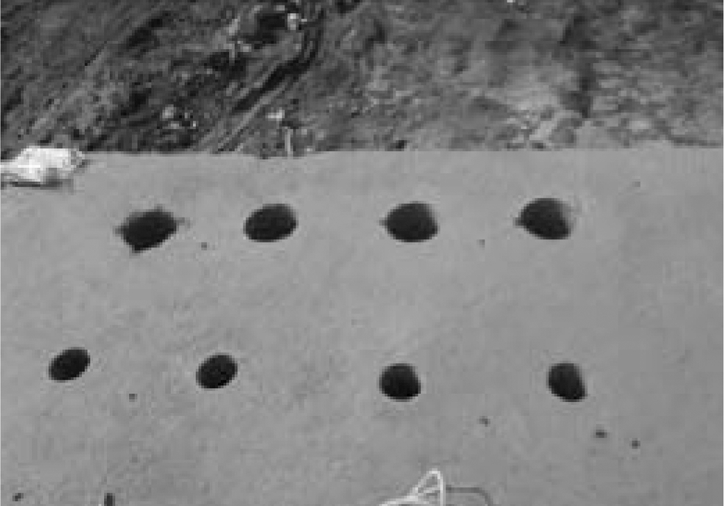
The experiment specimens are fabricated on top of the above concrete matrix. The procedure for making these specimens is shown in Fig.6. To eliminate the interactive impact of the adjacent pull-out tests, the distance between the centers of every two steel rebars is 500 mm.
Tab.1 List of test specimens of different connections
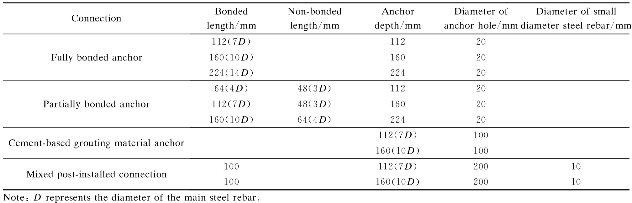
ConnectionBondedlength/mmNon-bondedlength/mmAnchordepth/mmDiameterofanchorhole/mmDiameterofsmalldiametersteelrebar/mmFullybondedanchor112(7D)11220160(10D)16020224(14D)22420Partiallybondedanchor64(4D)48(3D)11220112(7D)48(3D)16020160(10D)64(4D)22420Cement-basedgroutingmaterialanchor112(7D)100160(10D)100Mixedpost-installedconnection100112(7D)20010100160(10D)20010Note:Drepresentsthediameterofthemainsteelrebar.
(a)

(b)
(c)
Fig.6 The procedure of fabricating different specimens. (a) Fully bonded anchor; (b) Partially bonded anchor; (c) Drilled out concrete cylinder; (d) Cement-based grouting material anchor; (e) Small diameter steel rebar and stirrup installation; (f) Mixed post-installed connection
2.3 Pull-out test of specimen
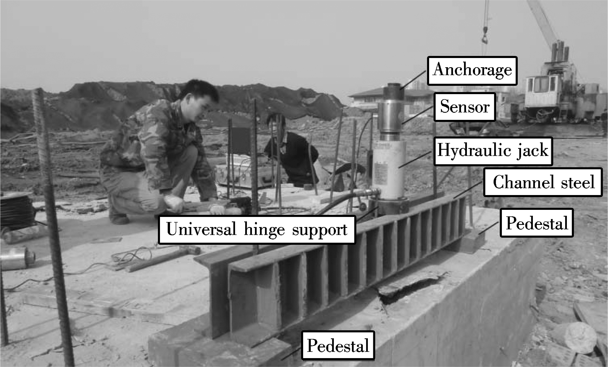
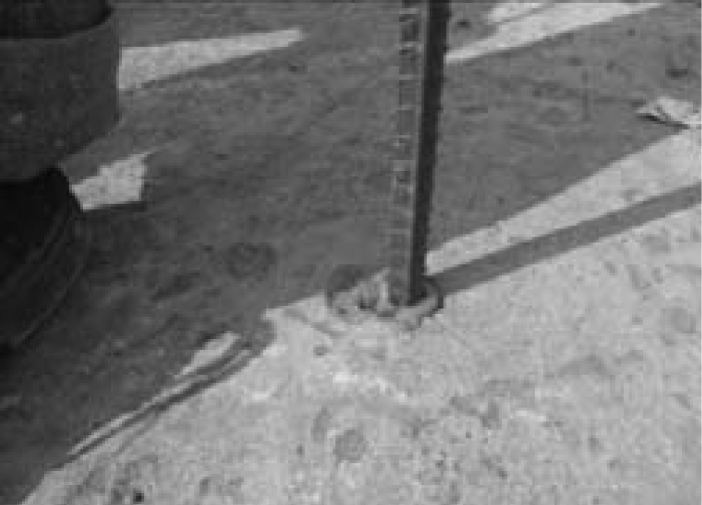
The pull-out test is an important method of investigating the mechanical performance of post-installed steel rebars[12]. Tests can divide the concrete surface conditions into two categories, unconfined and confined pull-out tests. The unconfined test can avoid stress on the concrete surface, which is consistent with the practical situation and can be used to study the planted bar performance under different failure modes. In this paper, an unconfined pull-out test is conducted, as shown in Fig.7. In the single reinforcement pull-out test, a center hole jack is applied to exert tension force onto the anchors. The testing procedure is as follows: First, two channel steel pedestals are placed onto the matrix with an interval at least four times that of the anchor depth; then, two channel steel beams are fixed onto the pedestals; next, the jack is mounted onto the two beams; finally, the pressure sensors and connection anchorage are installed in turn. Axial uniform load is applied by a manual hydraulic pump to the test specimens with slow increments up to anchor failure in 2 to 3 min.
2.4 Experimental results
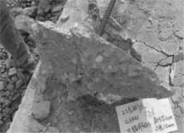
During the experimental process, the failure load and failure pattern of each specimen are carefully recorded, and the experimental results are listed in Tab.2 to Tab.5, where R1 is defined as the ratio of the failure load to the yield load of the steel rebar; and R2 is defined as the ratio of the failure load to the ultimate load of the steel rebar. The failure patterns are described in Fig.8.
Tab.2 Failure load and failure mode of the fully bonded anchor
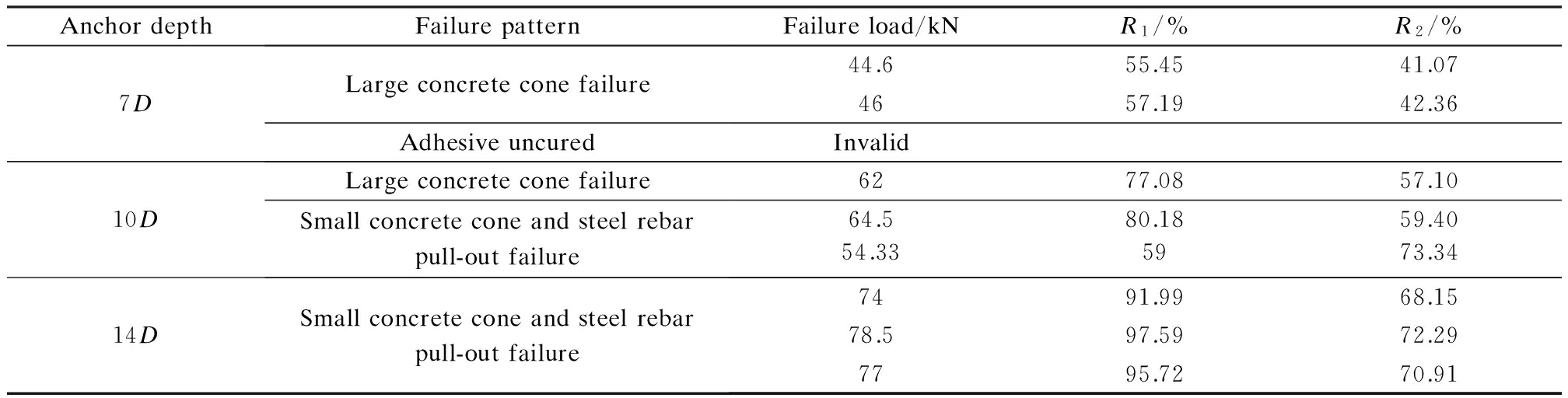
AnchordepthFailurepatternFailureload/kNR1/%R2/%7DLargeconcreteconefailureAdhesiveuncured44.655.4541.074657.1942.36Invalid10DLargeconcreteconefailureSmallconcreteconeandsteelrebarpull-outfailure6277.0857.1064.580.1859.405973.3454.3314DSmallconcreteconeandsteelrebarpull-outfailure7491.9968.1578.597.5972.297795.7270.91
Tab.3 Failure load and failure mode of the partially bonded anchor
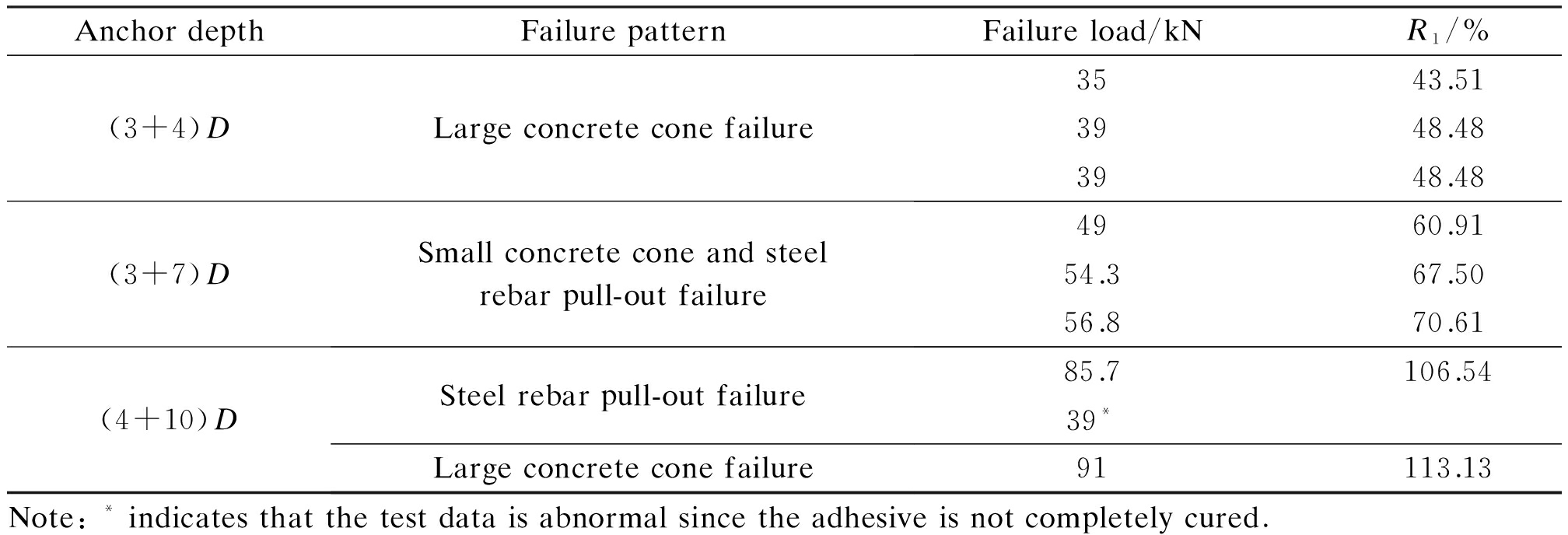
AnchordepthFailurepatternFailureload/kNR1/%R2/%(3+4)DLargeconcreteconefailure3543.5132.233948.4835.913948.4835.91(3+7)DSmallconcreteconeandsteelrebarpull-outfailure4960.9145.1254.367.5050.0056.870.6152.31(4+10)DSteelrebarpull-outfailureLargeconcreteconefailure85.7106.5478.9239*91113.1383.80Note:*indicatesthatthetestdataisabnormalsincetheadhesiveisnotcompletelycured.
Tab.4 Failure load and failure mode of the cement-based grouting material anchor
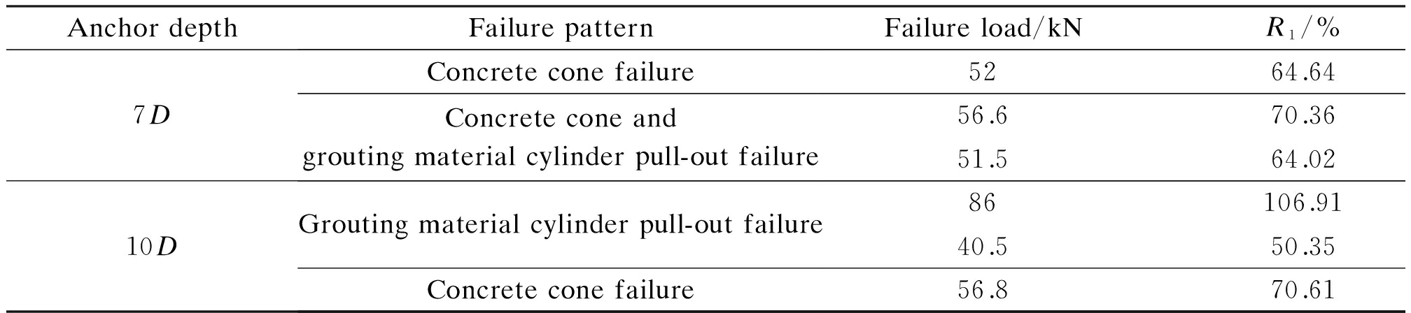
AnchordepthFailurepatternFailureload/kNR1/%R2/%7DConcreteconefailureConcreteconeandgroutingmaterialcylinderpull-outfailure5264.6447.8956.670.3652.1251.564.0247.4310DGroutingmaterialcylinderpull-outfailureConcreteconefailure86106.9179.2040.550.3537.3056.870.6152.31
Tab.5 Failure load and failure mode of mixed post-installed connections
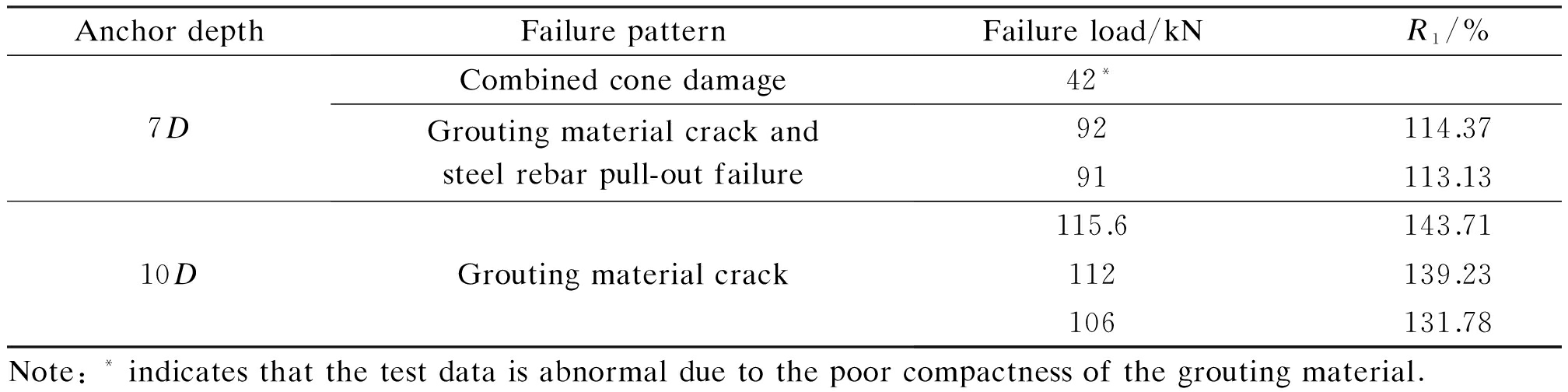
AnchordepthFailurepatternFailureload/kNR1/%R2/%7DCombinedconedamageGroutingmaterialcrackandsteelrebarpull-outfailure42*92114.3784.7291113.1383.8010DGroutingmaterialcrack115.6143.71106.46112139.23103.14106131.7897.61Note:*indicatesthatthetestdataisabnormalduetothepoorcompactnessofthegroutingmaterial.
(a)
(b)
(c)

(d)
(e)
Fig.8 The failure modes of specimens. (a) Large concrete cone failure; (b) Small concrete cone and steel rebar pull-out failure; (c) Steel rebar pull-out failure; (d) Grouting material cylinder pull-out failure; (e) Grouting material crack
2.5 Discussion
In the first case, a fully bonded post-installed adhesive anchor is employed. When anchorage lengths are 7D (112 mm) and 10D (160 mm), large concrete cone failure can easily occur due to the low strength of the concrete matrix, local cone-type concrete failure and steel reinforcement pull-out failure that are observed in some specimens, and failure load values are far less than the yield load value of rebar. When the anchored depth reaches 14D (224 mm), large concrete cone failure will not occur. All three specimens encounter local cone-type concrete failure and steel rebar pull-out failure, and the failure load values are close to the yield load values of the steel rebar.
As for partially bonded anchors, when the non-bonded length is 3D (48 mm) and the bonded length is 4D (64 mm), large concrete cone failure also easily occurs due to the low strength of the concrete substrate, and failure load value is only 1/2 of the yield load of the steel rebar. When the non-bonded length is 3D (48 mm) and bonded length is 7D (112 mm), all three specimens fail because they pull out with the small concrete cone. This proves that adding non-bonded section cannot prevent cone failure caused by insufficient tensile strength in low-strength concrete. The failure load is approximately 2/3 of the yield load of the steel rebar. When the non-bonded length is 4D (64 mm) and the bonded length is 10D (160 mm), large concrete cone failure and steel rebar pull-out failure occur, which confirms that increasing the non-bonded length can avoid small concrete cone failure. However, the steel rebar is embedded so deep into the concrete that adhesive construction quality is poor, and then the steel rebars pull out.
In the third case, the cement-based grouting material is designed to replace local low-strength concrete. The results indicate that when the anchorage length is 7D, large concrete cone failure also easily occurs due to the low strength of the concrete matrix, and the failure load value is only 2/3 of the yield load value. When the anchorage length is 10D, concrete cone and grouting material cylinder are pulled out due to the insufficient bonding capacity at the interfaces of the concrete and grouting materials. The proposed mixed post-installed connections perform well in tests. Concrete cone failure does not occur in all the tests. When the anchorage length is 7D, the failure load exceeds the yield load of rebar but is still less than the ultimate load; however, due to poor grouting material quality, the data of one specimen is not used. When the anchorage length is 10D, the failure load of which exceeds the ultimate load of the steel rebar, all the failure patterns crack in the grouting material. Hence, the proposed mixed connection structure can make good changes in failure pattern and improve the bearing capacity of the post-installed anchor in low-strength concrete. On the basis of fine construction, the strong mechanical performance requirements of the post-installed anchor in low-strength concrete can be achieved.
For the application of the mixed post-installed connection, the requirement for micro expansion of the cement-based grouting material is that the shrinkage of grouting material can be completely compensated, while the pre compressive stress can reach 0.2 to 0.7 MPa under the constraint condition. The proposed bonded length of the small diameter steel rebar is 10 times its diameter. The suggested anchor depth of the main steel rebar is 10D, and the diameter of the cement-based grouting material is 200 mm.
3 Conclusion
In this paper, the methods of improving the bearing capacity of post-installed steel rebar are experimentally studied. In single reinforcement pull-out tests, four connection structures are designed to verify the efficiency and reliability of the proposed bonding connections. When the partially bonded anchor is adopted, reasonable bonded and non-bonded length of anchors can prevent small concrete cone failure, and greatly increase the bearing capacity of the connection joint. For the lack of sufficient number of specimens, the quantitative conclusion of the partially bonded anchors cannot be drawn. The cement-based grouting material anchor system seems to be useless for increasing bearing capacity. Due to the significant difference of the surface treatment between the concrete and grouting materials, the pull-out failure of the grouting material cylinder will occur, and the deviations of failure load are large. A mixed post-installed connection is recommended, which can effectively improve the bearing capacity of a single rebar. Owing to the lapping small diameter steel bar and constraints of grouting material core by the stirrups, the failure load is greater than the design capacity of the steel rebar. If the size of the concrete base is sufficient, the mixed post-installed anchor system is very suitable in practice.
[1]Cook R A, Konz R C. Factors influencing bond strength of adhesive anchors[J]. ACI Structural Journal, 2001, 98(1): 76-86.
[2]Upadhyaya P, Kumar S. Pull-out capacity of adhesive anchors: An analytical solution[J]. International Journal of Adhesion and Adhesives, 2015, 60: 54-62. DOI:10.1016/j.ijadhadh.2015.03.006.
[3]Eligehausen R, Cook R A, Appl J. Behavior and design of adhesive bonded anchors[J]. ACI Structural Journal, 2006, 103(6): 822-831.
[4]Akiyama T, Yamamoto Y, Ichihashi S, et al. Experimental study on performance of bonded anchors in the low strength reinforced concrete[C]//International Symposium on Connections Between Steel and Concrete. Stuttgart, Germany, 2001: 371-380.
[5]Maz lgüney L. Tensile behavior of chemically bonded post-installed anchors in low-strength reinforced concretes [D]. Ankara, Turkey: The Graduate School of Natural and Applied Sciences of Middle East Technical University, 2007.
[6]Yang S, Wu Z, Hu X, et al. Theoretical analysis on pullout of anchor from anchor-mortar-concrete anchorage system[J]. Engineering Fracture Mechanics, 2008, 75(5): 961-985. DOI:10.1016/j.engfracmech.2007.05.004.
[7]Wang D P, Wu D S, Ouyang C J, et al. Performance and design of post-installed large diameter anchors in concrete [J]. Construction and Building Materials, 2016, 114: 142-150. DOI:10.1016/j.conbuildmat.2016.03.167.
[8]Wang D P, Wu D S, He S M, et al. Behavior of post-installed large-diameter anchors in concrete foundations [J]. Construction and Building Materials, 2015, 95: 124-132. DOI:10.1016/j.conbuildmat.2015.07.129.
[9]Contrafatto L, Cosenza R. Behaviour of post-installed adhesive anchors in natural stone [J]. Construction and Building Materials, 2014, 68: 355-369. DOI:10.1016/j.conbuildmat.2014.05.099.
[10]Yilmaz S, Özen M A, Yardim Y. Tensile behavior of post-installed chemical anchors embedded to low strength concrete[J]. Construction and Building Materials, 2013, 47: 861-866. DOI:10.1016/j.conbuildmat.2013.05.032.
[11]Xie Q, Zhao Y Q, Tang S L. Bond-slip behavior of post-installed reinforcement in concrete with inorganic adhesive [J]. Journal of Xi’an University of Architecture and Technology: Natural Science Edition, 2015, 47(6): 838-842. DOI:10.15986/j.1006-7930.2015.06.014. (in Chinese)
[12]Kim J S, Jung W Y, Kwon M H, et al. Performance evaluation of the post-installed anchor for sign structure in South Korea[J]. Construction and Building Materials, 2013, 44: 496-506. DOI:10.1016/j.conbuildmat.2013.03.015.
References:
低强度混凝土基材上新型后锚固连接构造的受力性能
王永泉1 陈天骄1 景 剑2
(1河海大学水利水电学院, 南京 210098)(2河海大学土木与交通学院, 南京 210098)
摘要:为解决低强度混凝土基材上化学植筋承载力不足的技术难题,提出了一种采用小直径钢筋植筋+灌浆料锚固的新型混合连接构造.为验证所提连接构造的可行性,设计了4种锚固连接构造的对比试验,包括植筋胶全粘结、植筋胶部分粘结、灌浆料连接和新型混合连接.单筋拉拔实验结果显示,新型混合连接构造可有效提高低强度混凝土基材上的化学植筋承载能力,相对于植筋胶全粘结的连接构造,承载力提高近2倍,且不会出现混凝土椎体破坏.结果表明:对于在低强度混凝土基材上进行钢筋后锚固连接,若空间尺寸满足要求,可采用新型混凝土连接构造,确保节点连接性能满足要求.
关键词:低强度混凝土;新型连接构造;化学植筋;承载力;破坏形态
中图分类号:TV331
Received:2016-09-04.
Foundation item:s:The National Natural Science Foundation of China (No.51409084), the Natural Science Foundation of Jiangsu Province(No.BK20130836).
Citation::Wang Yongquan, Chen Tianjiao, Jing Jian. Mechanical performance of the mixed post-installed connection in low-strength concrete[J].Journal of Southeast University (English Edition),2017,33(2):203-208.
DOI:10.3969/j.issn.1003-7985.2017.02.013.
DOI:10.3969/j.issn.1003-7985.2017.02.013
Biography:Wang Yongquan(1981—), male, doctor, associate professor, wyq_hhu@hhu.edu.cn.
 (b)
(b)