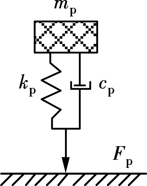
Fig.1 MMSD biodynamic model
Abstract:The human-induced vertical vibration serviceability of low-frequency and lightweight footbridges is studied based on the moving mass-spring-damper (MMSD) biodynamic model, and the mass damper (TMD) with different optimal model parameters being used to control the vertical vibration. First, the MMSD biodynamic model is employed to simulate the pedestrians, and the time-varying control equations of the vertical dynamic coupling system of the pedestrian-bridge-TMD are established with the consideration of pedestrian-bridge dynamic interaction; and the equations are solved by using the Runge-Kutta-Felhberg integral method with variable step size. Secondly, the footbridge dynamic response is calculated under the model of pedestrian-structure dynamic interaction and the model of moving load when the pedestrian pace frequency is consistent with the natural frequency of footbridge. Finally, a comparative study and analysis are made on the control effects of the vertical dynamic coupling system in different optimal models of the TMD.The calculation results show that the pedestrian-bridge dynamic interaction cannot be ignored when the vertical human-induced vibration serviceability of low-frequency and light-weight footbridge is evaluated.The TMD can effectively reduce the vibration under the resonance of pedestrian-bridge, and TMD parameters are recommended for the determination by the Warburton optimization model.
Key words:footbridge; vibration serviceability; biodynamic;dynamic coupling system; vibration control
With extensive use of high-strength materials, footbridges tend to be of lower frequency, slender and lightweight, and more sensitive to human-induced excitation, resulting in human-induced vibration serviceability problems[1]. Human-induced excitation simultaneously causes vertical and horizontal vibration of the footbridge. A significant horizontal vibration will occur when multiple pedestrians walk on the flexible structures. However, perceptible vertical vibration in ordinary footbridges can be induced even by a single walking pedestrian[2]. As a self-adaptive, intelligent driving force, pedestrians may adjust their footsteps in response to the vibration of the footbridge, which is accordingly influenced by footsteps and vice versa, forming a human-bridge interaction[3-4]. Nevertheless, engineers know little about this human-structure interaction mechanism, and it is almost ignored in footbridge designs. The recommended method for calculating the human-induced vibration is one where pedestrian load acting on the bridge is treated as moving load expressed in the Fourier series[5] and is applicable to most cases. However, if it is employed in lightweight constructions, particularly when the natural vibration frequency of the structure is consistent with that of pedestrians, there is great difference between the estimated results and measured values[4,6].
The dynamic interaction model of the pedestrian-structure should be established in order to obtain a reliable measurement in the vibration serviceability of a structure. Currently, available pedestrian-structure dynamic models consist of the moving mass-spring-damper (MMSD)[7], the inverted pendulum model[8] and the bipedal model[9]. The MMSD is a single degree of the freedom dynamic system, in which human weight is concentrated at the center of gravity, thus, the mechanical impedance of the lower limbs and the energy dissipation of the human body can be, respectively, expressed in the parameters of mass, stiffness and damping. These are related to the three empirical functions concerning pacing frequency and body weight[10]. This model is extensively applied in human-structure dynamic interaction[11-12] and it exhibits explicit physical meaning and it easily forms a dynamic coupling system with the structure.
The tuned mass damper (TMD) is a vibration control system composed of mass, spring and damping, and it is widely used in resistance against vibration of the structure under earthquake or wind load. In order to satisfy the vertical vibration serviceability of footbridge, the application of the TMD is becoming more typical in the current design of footbridges[13-14]. According to different design criteria, different optimal TMD characteristics can be obtained, thus reducing the structural response to harmonic loading condition or random loading (such as white noise) characterized by a uniform spectrum[15]. For the TMD installed in the box girder of the footbridge, apart from vibration reduction, the displacement limit of the structure needs to be taken into consideration in its design and fabrication.
On the basis of some research results obtained by other scholars, this paper attempts to establish the time-varying control equations of the human-bridge-TMD vertical dynamic coupling system by simulating pedestrian-structure interaction based on the MMSD biodynamic model and solves the equations by using Runge-Kutta integration method with variable step size on a Matlab computing platform. The dynamic response when the pedestrian pace frequency is consistent with the natural frequency of the footbridge is calculated under the dynamic interaction model and moving load model, and a comparative study and analysis are made on the control effects of the vertical dynamic coupling system in three different optimal model parameters of the TMD.
The MMSD biodynamic model simulating pedestrian walking is proposed by Archbold et al.[8], as shown in Fig.1. The model is composed of two parts: The pedestrian biodynamic parameters mp, kp and cp,and the pedestrian walking load Fp.
Fig.1 MMSD biodynamic model
The walking dynamic parameters were obtained from the test of 34 males and 1 female in Ref.[16], and the correlative analysis was made among these parameters. Some relevant formulas in Ref.[16]are therefore improved, and then the pedestrian biodynamic parameters can be represented by the pedestrian body mass M and stride frequency fp:
mp= -231.34+3.69M+154.06fp-1.97Mfp+

(1)
cp= -1 115.69+92.56M-108.94mp+

(2)
kp= 75 601-1 295.32M-33 786.75fp+

(3)
The pedestrian walking load Fp is[4]
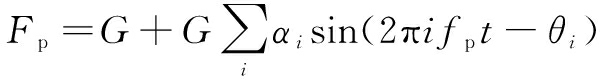
(4)
where G is the weight of pedestrian, generally equal to 750 N; αi and fi are the dynamic load factor and walking frequency, respectively. The phase angle θi often equals 0, and i is the term of inter-harmonics adopted in the calculation. The dynamic load factors are generally taken the former three steps as follows:
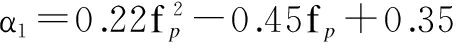
(5a)
α2=0.024+6.87×10⁻⁵cp-2.4×10⁻⁶kp
(5b)
α3= -0.064+0.002 4M-1.1×10⁻⁶kp+
1.0×10⁻⁸Mkp-1.38×10⁻⁵M2
(5c)
The dynamic response of the structure was calculated based on the above MMSD biodynamic model in Refs.[5,17], and the calculated results were in agreement with the experimental results. It shows that the MMSD biodynamic model can be used in the calculation of the pedestrian-structure dynamic coupling system.
Traditionally, in the case of harmonic loading, the optimization of the frequency ratio and the TMD’s damping aims at minimizing the structural response by minimizing the structural dynamic magnification function. The optimum TMD damping ratio is determined as the arithmetic mean of the values that give the maximum dynamic magnification at the two fixed points. The optimum values of the frequency ratio and the TMD damping ratio[15] can be obtained.

(6)

(7)
where λopt, μ are the frequency ratio and the mass ratio between the TMD and the structure control model, respectively; ξdoptis the damping ratio of the TMD.
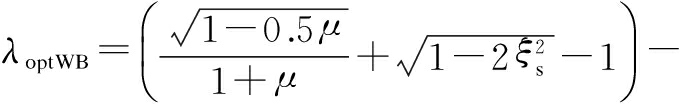
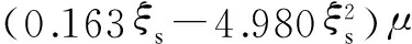
The optimization design of the TMD under white noise was introduced by Warburton et al[18]. The optimal parameters, which can minimize the variance of the structural response, are obtained.
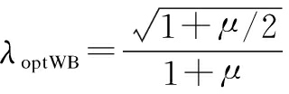
(8)
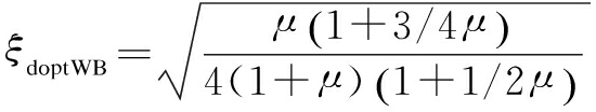
(9)
Eqs.(6) to (9) are based on the assumptions of none of the damping structures of the TMD optimization model, and Tsai et al.[19] deduced the design formulas for the damping structure:


(10)

(11)
where ξs is the damping ratio of structure.
The vertical coupling dynamic system consists of a pedestrian, footbridge and TMD, as shown in Fig.2. The footbridge is assumed to be the uniform section Euler-Bernoulli beam. L is the span of footbridge; E and I are the elastic modulus and section moment of inertia, respectively; m is the mass of footbridge per unit length. The pedestrian can be described by the MMCK biodynamic model, where md, kd and cd are the mass, stiffness and damping of the TMD; v is the walking speed of pedestrian, which is generally 0.9 times that of the stride frequency; up, ud and u are the vertical displacements of the pedestrian, TMD and footbridge, respectively; ![]() is the position of the TMD, and t is the walking time. There is an assumption that the pedestrian and bridge always remain in contact when the pedestrian is walking.
is the position of the TMD, and t is the walking time. There is an assumption that the pedestrian and bridge always remain in contact when the pedestrian is walking.
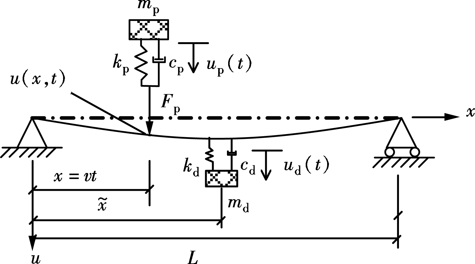
Fig.2 Pedestrian-bridge-TMD dynamic coupling system
The equations of the motion of the structure, pedestrian and TMD can be written in the following forms, respectively:
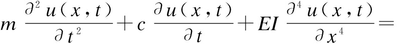


(12)

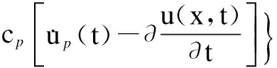
(13)

(14)
where δ is the Dirac equation. Substituting ![]() yn(t)φn(x) into the above equations, where φn(x) is the n-order vibration mode function and yn is the generalized ordinates, Eqs.(12), (13) and (14) can be, respectively, re-written as follows:
yn(t)φn(x) into the above equations, where φn(x) is the n-order vibration mode function and yn is the generalized ordinates, Eqs.(12), (13) and (14) can be, respectively, re-written as follows:
![]() φm(vt)φn(vt)+
φm(vt)φn(vt)+

![]()
![]() φn(vt)-
φn(vt)-


(15)

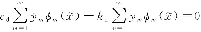
![]() φm(vt)=0
φm(vt)=0
(16)

(17)
where mn, ξn and ωn=2πfn are the n-order modal mass, the modal damping ratio and the modal circle frequency, respectively.
Combining Eqs.(15), (16) and (17) can obtain the control equation of the pedestrian-bridge-TMD dynamic coupling system, and the control equation can be written in the following matrix form:
(18)
The mass matrix M, the damping matrix C and the stiffness matrix K are given as follows:
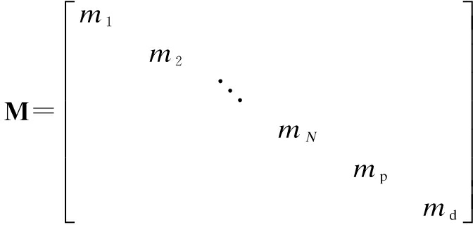
(19a)

(19b)
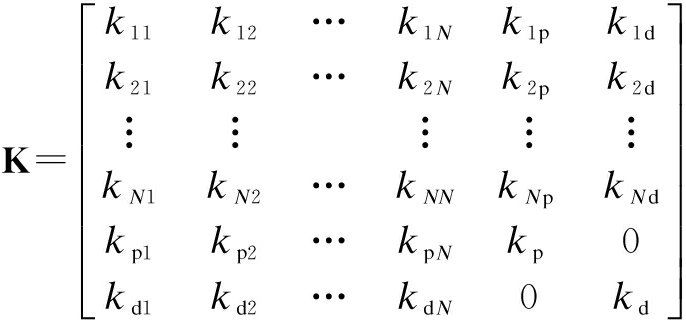
(19c)
The matrix elements in Eq.(19) can be given by

kip=kpi=-kpφi(vt)


i,j=1,2,…,N;i≠j
cip=cpi=-cpφi(vt)


i,j=1,2,…,N;i≠j
The displacement vector y and the force vector F in Eq.(18) are given as
y=[y1,y2,…,yN,up,ud]T
(20)
F=[ρFφ1,ρFφ2,…,ρFφN,0,0]T
(21)
where ![]() ). When the pedestrian is crossing the footbridges, K, C and F change continuously, and then the control equations of the pedestrian-bridge-TMD vertical dynamic coupling system become time varying second-order differential equations. On the Matlab computing platform, the Runge-Kutta integration method with variable step size was used to solve the time varying control equations of the dynamic coupling system.
). When the pedestrian is crossing the footbridges, K, C and F change continuously, and then the control equations of the pedestrian-bridge-TMD vertical dynamic coupling system become time varying second-order differential equations. On the Matlab computing platform, the Runge-Kutta integration method with variable step size was used to solve the time varying control equations of the dynamic coupling system.
The example is a lightweight cable-stayed footbridge made of the FRP material. The main span of the footbridge is 63 m and the main span part of the footbridge is regarded approximately as a simple beam just like that in Ref.[20]. By means of the modal test of the footbridge, it can be determined that the main mode shape of the bridge is the first-order vertical vibration. The vibration frequency is 1.52 Hz, the damping ratio is 0.42%, and the modal mass is 2 750 kg.
4.1 Pedestrian-bridge dynamic interaction
When a pedestrian walks on the footbridge in accord with the first-order resonance frequency of 1.52 Hz, the acceleration time history curves of the bridge under the action of the moving load model and the interaction model are shown in Fig.3.
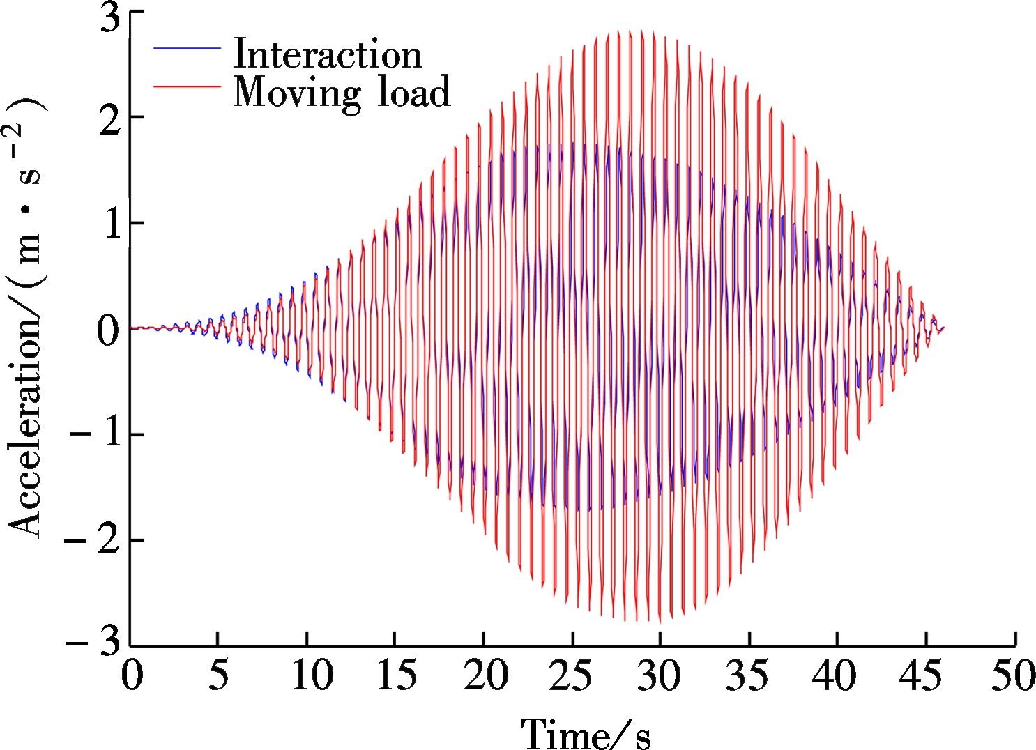
Fig.3 Acceleration time responses of the footbridge under different loading models
As shown in Fig.3, the peak value of acceleration of the pedestrian bridge under the moving load model is 2.79 m/s2,while under the interaction model, the peak value of acceleration is 1.75 m/s2, which is reduced by 37%. It can be seen that, for the light and low frequency structure, the dynamic interaction of the pedestrian-structure cannot be ignored. Although the dynamic interaction of the human-bridge is taken into account, the peak value of the acceleration of the pedestrian bridge is still greater than the limit value of 0.70 m/s2[21].Therefore, it is necessary to control the vibration of the pedestrian bridge.
4.2 TMD control of dynamic coupling system
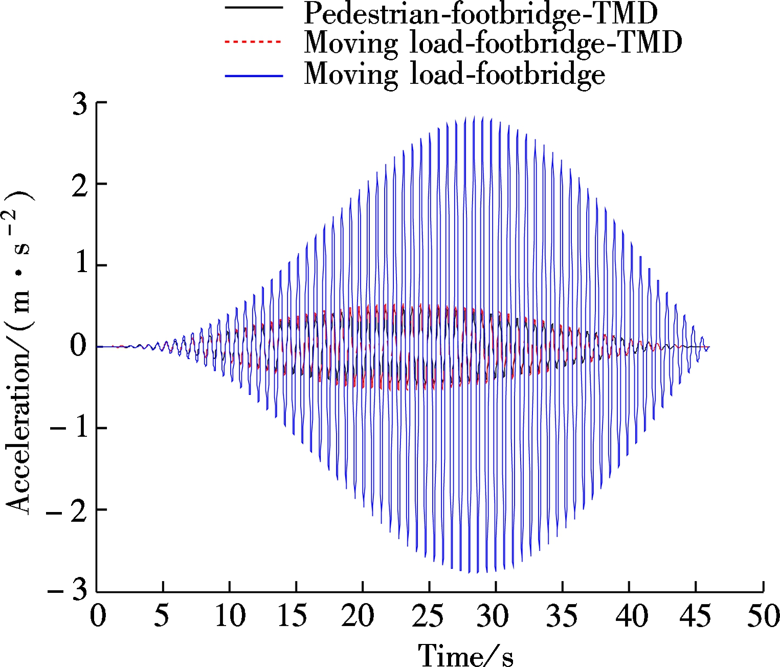
According to the Den Hartog optimization model, the design parameters of TMD were obtained to control the first-order mode of the pedestrian bridge with the mass ratio μ of 0.01. The pedestrian-footbridge-TMD dynamic coupling model not only installs TMD but also considers pedestrian-bridge interaction, the moving load-footbridge-TMD dynamic coupling model installs TMD without considering the pedestrian-bridge interaction, and the moving load-footbridge neither installs TMD nor considers pedestrian-bridge interaction. Fig.4 is the dynamic responses of the footbridge according to different coupling models when a pedestrian goes through the footbridge with a walking frequency equal to the first-order resonance frequency of 1.52 Hz.
In order to confirm whether the strength of the structure is impacted after the installation of TMD, the finite element software ANSYS is used to analyze the strength of the structure. TMD is installed in the secondary beam via bolts and the beam is of the steel type Q235, of which the stress intensity is 210 GPa and the mass of TMD is 27.5 kg. The stress intensities of structure under the action of gravity and pedestrian load are calculated and the maximum stress intensities are 2.10 and 2.24 MPa, respectively, which is far less than the maximum stress intensity of Q235 steel. Under the two conditions, the maximum principal stresses at the joint of the main beam and the secondary beam are 17 232 and 18 369 Pa, respectively, which is less than the tensile strength of the bolt. So, the structure remains safe.
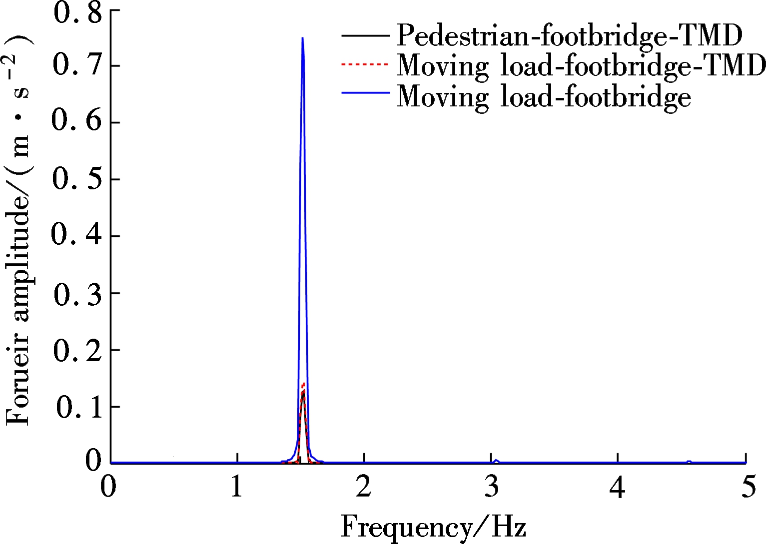
As shown in Fig.4(a), after installing the TMD, the peak acceleration of the footbridge from the moving load model of 1.75 m/s2 reduces to the pedestrian-footbridge-TMD coupling dynamic model of 0.47 m/s2and the footbridge-TMD coupling dynamic model of 0.53 m/s2, and the ratios of vibration mitigation are 73.7% and 69.7%, respectively; which meet the requirements of vertical vibration serviceability. It can also be seen that, after installing the TMD, the responses of bridge under the action of moving load model and interaction model are almost equal. Employing the fast Fourier transform into acceleration time history, the FFT spectrum curve is shown in Fig.4(b), from which a similar conclusion as Fig.4(a) can be reached.
(a)
(b)
Fig.4 Dynamic response of footbridge with different dynamic coupling systems. (a) Acceleration time history; (b) FFT spectrum curve
4.3 TMD control effects of different optimization models
Tab.1 presents the TMD optimization parameters of three different optimization models in three typical mass ratios.
Tab. 1 Optimal parameters of TMD
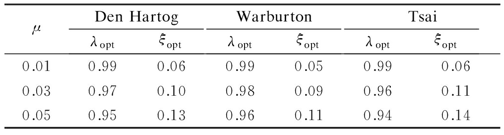
μDenHartogλoptξoptWarburtonλoptξoptTsaiλoptξopt0.010.990.060.990.050.990.060.030.970.100.980.090.960.110.050.950.130.960.110.940.14
As shown in Tab.1, the optimal frequency ratios obtained by different optimization models are not so different, but the optimal damping ratios are quite different. Among them, the minimum damping ratio is obtained by the Warburton optimization model,and the maximum damping ratio is obtained by the Tsai model. In addition, with the increase of the mass ratio, the damping ratio increases.
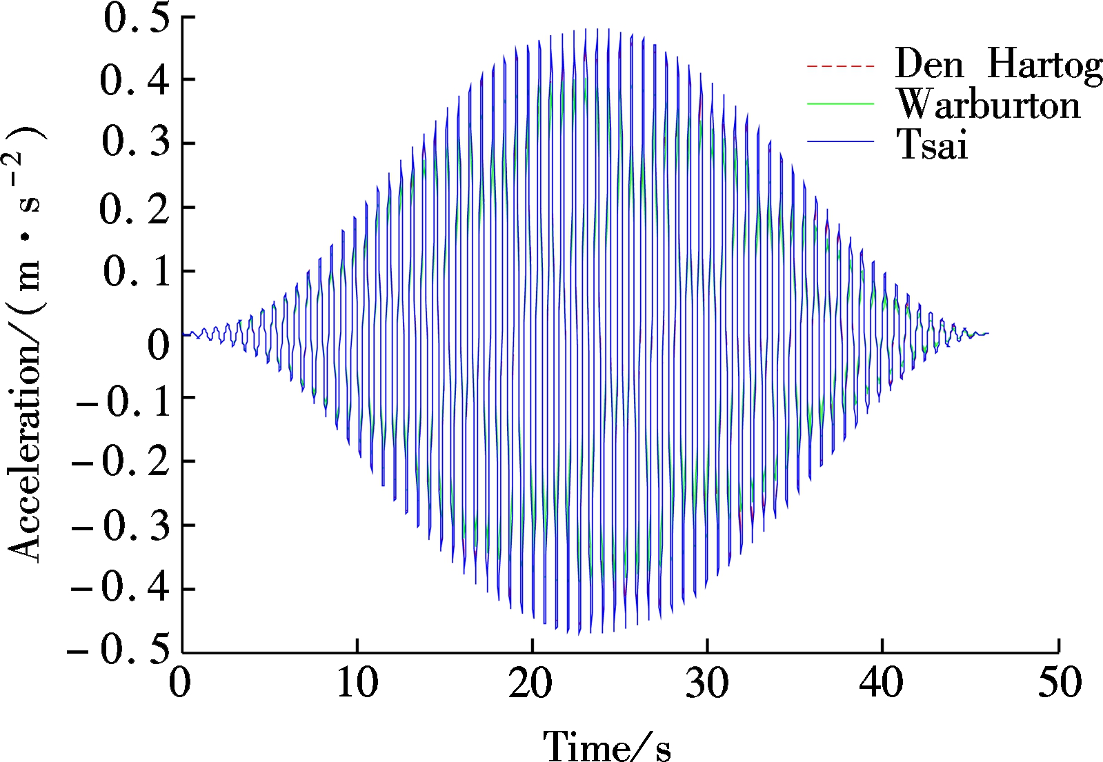
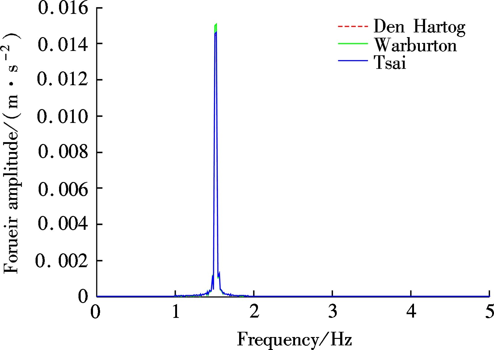
The responses of the footbridge of the pedestrian-footbridge-TMD vertical dynamic coupling system are shown in Fig.5 when the mass ratio equals 0.01, and the TMD uses different optimization parameters. It can be seen in Fig.5(a) that, when a pedestrian walks with the first-order resonance frequency of 1.52 Hz, after the TMD is installed in the footbridge with different model parameters of Den Hartog, Warburton and Tsai, the peak accelerations are 0.47, 0.40 and 0.48 m/s2,respectively. Correspondingly, the damping rates are 73.7%, 77.1% and 72.6%, respectively, and all of them meet the requirements of vibration serviceability. Particularly, the Warburton optimization model has the best vibration mitigation.
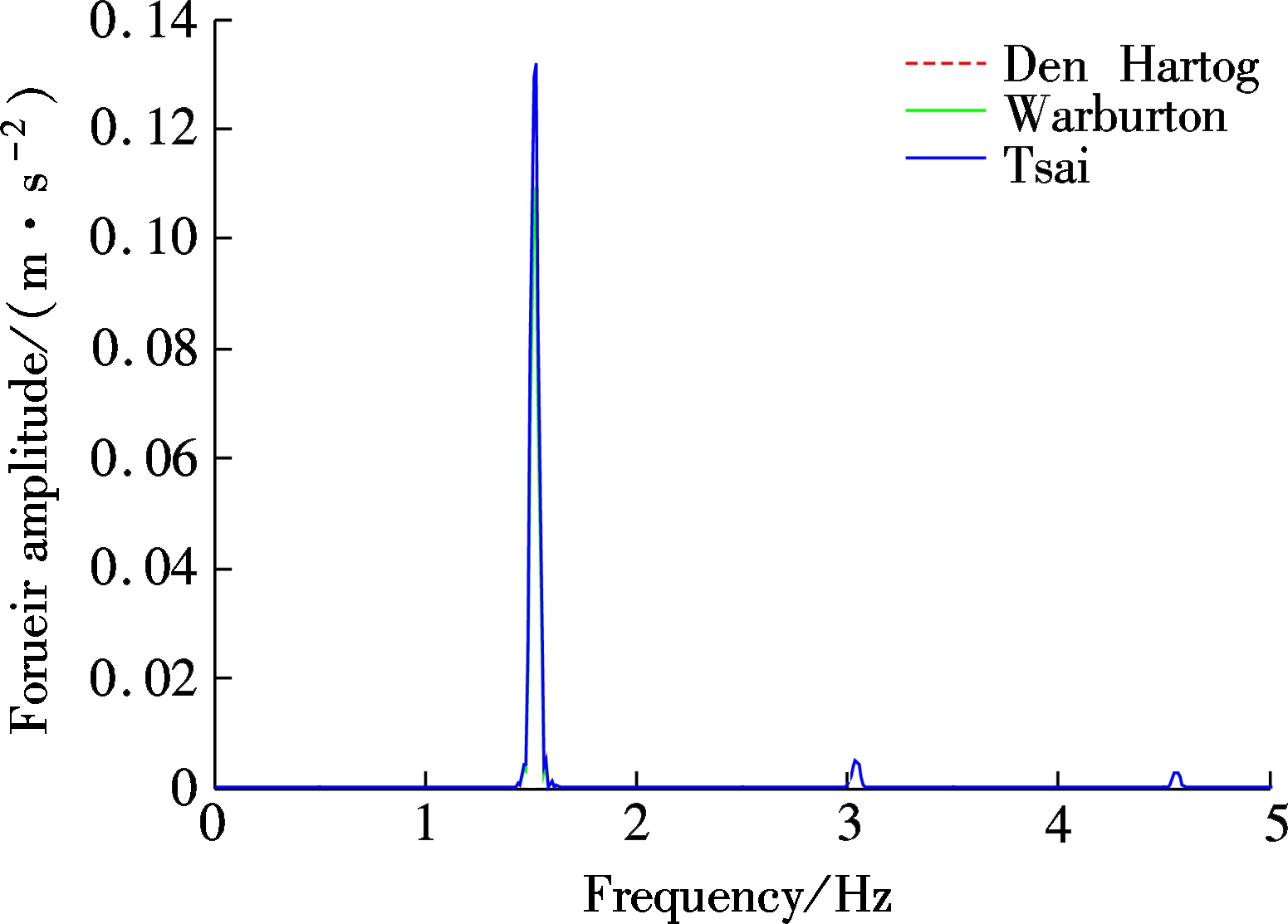
With the fast Fourier transform of the acceleration time history of different optimization models of TMD, we can obtain the FFT spectrum curves, as shown in Fig.5(b). Clearly, when a pedestrian passes through the footbridge with the first-order resonance frequency of 1.52 Hz, the Warburton model has the best optimal damping effect, the Den Hartog model follows, and the Tsai model is the poorest. However, the ratio of vibration mitigation of different optimization models is almost the same when doubling walking frequency.
(a)
(b)
Fig.5 Dynamic responses of footbridge with different optimation models of TMD. (a) Acceleration time history; (b) FFT spectrum curve
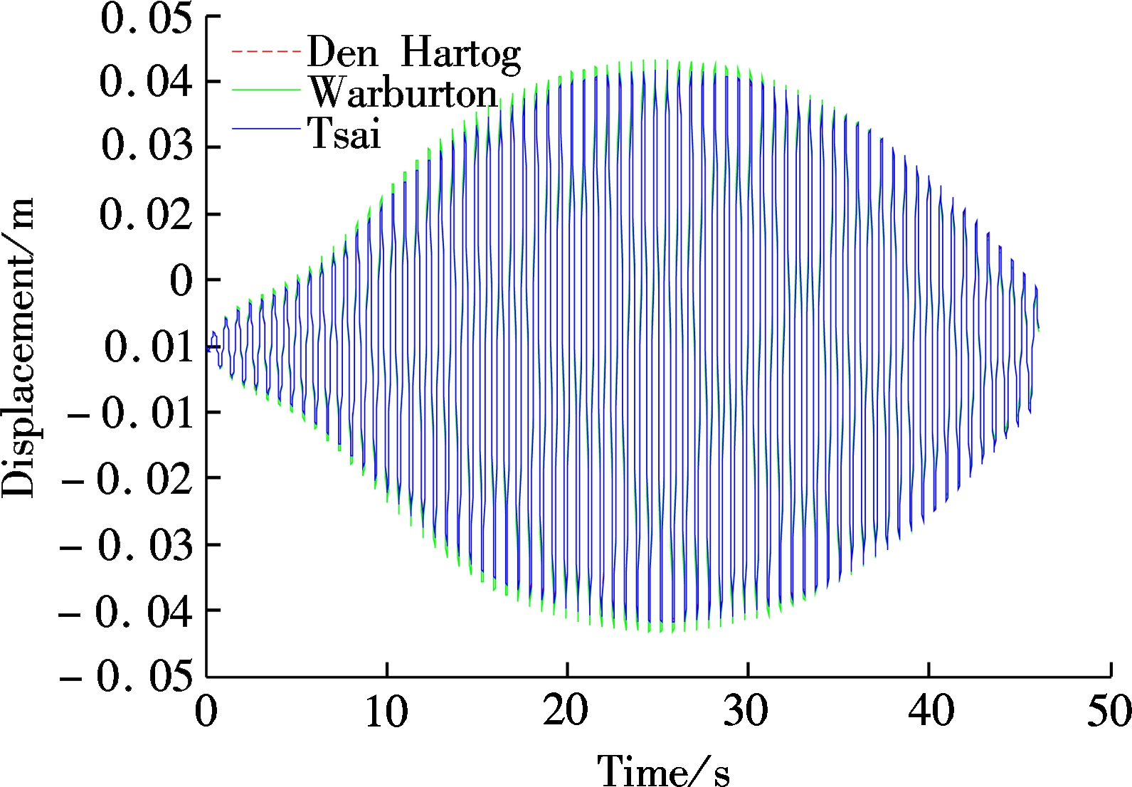
Fig.6 shows TMD relative displacement dynamic response when the pedestrian walks along the footbridge with the fundamental frequency of 1.52 Hz. As can be seen from the figure, using parameters of the optimization models of Den Hartog, Warburton and Tsai, the peak values of relative displacements are 0.042, 0.043 and 0.041 m, in which the optimization model of Tsai requires the minimum space for the installation of TMD. When making the fast Fourier transform on the relative displacement of TMD, the FFT spectral curve can be obtained, as shown in Fig.6(b), indicating that the relative displacement of TMD is mainly generated by doubling stride frequency, but the relative displacements of the three optimization models of TMD show not much difference.
(a)
(b)
Fig.6 Dynamic responses of TMD with different optimation models. (a) Acceleration time history;(b) FFT spectrum curve
1) The dynamic human-bridge interaction cannot be ignored when the vertical human-induced vibration serviceability of the low-frequency and lightweight footbridge is evaluated. The calculation results indicate that a 29.4% peak acceleration difference of footbridge is expected when the pedestrian pace frequency is consistent with the natural frequency of the footbridge under the action of the moving load model and interaction model.
2) The TMD can effectively reduce the vibrations of the footbridge caused by pedestrian-bridge resonance. An example reveals that the vibration mitigation ratio reaches up to 73.3% by using the TMD. Meanwhile, under the action of the moving load model and the interaction model, the response of the acceleration are almost equal.
3) Employing the different optimization models of Warburton, Krenk and Den Hartog to design the TMD, the decreasing amplitude ratios of the pedestrian bridge and the relative displacement of the TMD show no significant difference. Whereas, under Warburton’s model, less damping is needed. So, the Warburton optimization model is recommended to control the vibrations of the footbridge.
[1]Žcaronivanovi![]() S, Pavi
S, Pavi![]() A. Quantification of dynamic excitation potential of pedestrian population crossing footbridges[J]. Shock and Vibration, 2011, 18(4): 563-577.
A. Quantification of dynamic excitation potential of pedestrian population crossing footbridges[J]. Shock and Vibration, 2011, 18(4): 563-577.
[2]van Nimmen K, Lombaert G, de Roeck G, et al. Vibration serviceability of footbridges: Evaluation of the current codes of practice[J]. Engineering Structures, 2014, 59: 448-461. DOI:10.1016/j.engstruct.2013.11.006.
[3]Qin J W, Law S S, Yang Q S, et al. Finite element analysis of pedestrian-bridge dynamic interaction[J]. Journal of Applied Mechanics, 2014, 81(4): 041001. DOI:10.1115/1.4024991.
[4]Dang H V, Živanovi![]() S. Modelling pedestrian interaction with perceptibly vibrating footbridges[J]. FME Transactions, 2013, 41(4): 271-278.
S. Modelling pedestrian interaction with perceptibly vibrating footbridges[J]. FME Transactions, 2013, 41(4): 271-278.
[5]Kerr S C, Bishop N W M. Human induced loading on flexible staircases[J]. Engineering Structures, 2001, 23(1): 37-45. DOI:10.1016/s0141-0296(00)00020-1.
[6]da Silva F T, Brito H M B F, Pimentel R L. Modeling of crowd load in vertical direction using biodynamic model for pedestrians crossing footbridges[J]. Canadian Journal of Civil Engineering, 2013, 40(12): 1196-1204. DOI:10.1139/cjce-2011-0587.
[7]Shahabpoor E, Pavic A, Racic V. Identification of mass-spring-damper model of walking humans[J].Structures,2015,5:233-246.
[8]Archbold P, Keogh J, Caprani C C, et al. A parametric study of pedestrian vertical force models for dynamic analysis of footbridges[C/OL]// EVACES Conference. 2011:1-8. http://arrow.dit.ie/engschcivcon/39/.
[9]Macdonald J H G. Lateral excitation of bridges by balancing pedestrians[J]. Proceedings of the Royal Society of A: Mathematical, Physical and Engineering Sciences, 2008, 465(2104):1055-1073. DOI: 10.1098/rspa.2008.0367.
[10]Qin J W, Law S S, Yang Q S, et al. Pedestrian-bridge dynamic interaction, including human participation[J]. Journal of Sound and Vibration, 2013, 332(4): 1107-1124. DOI:10.1016/j.jsv.2012.09.021.
[11]Silva F T, Pimentel R L. Biodynamic walking model for vibration serviceability of footbridges in vertical direction[C]//Proceedings of the 8th International Conference on Structural Dynamics. Leuven, Belgium, 2011: 1090-1096.
[12]Živanovi![]() S. Modelling human actions on lightweight structures: Experimental and numerical developments[C/OL]//MATEC Web of Conferences. 2015:01005-1-01005-13. http://www.matec-conferences.org.
S. Modelling human actions on lightweight structures: Experimental and numerical developments[C/OL]//MATEC Web of Conferences. 2015:01005-1-01005-13. http://www.matec-conferences.org.
[13]Pfeil M, Amador N, Pimentel R, et al. Analytic-numerical model for walking person-footbridge structure interaction[C]//Proceedings of the 9th International Conference on Structural Dynamics. Porto, Portugal,2014: 1079-1086.
[14]Li X W, He B, Shi W X. Application of TMD seismic vibration control system in the bridge structures [J]. China Civil Engineering Journal, 2013, 46(S1): 245-250.(in Chinese)
[15]van Nimmen K, Verbeke P, Lombaert G, et al. Numerical and experimental evaluation of the dynamic performance of a footbridge with tuned mass dampers[J]. Journal of Bridge Engineering, 2016, 21(8): C4016001. DOI:10.1061/(asce)be.1943-5592.0000815.
[16]Den Hartog J P. Mechanical vibrations[M]. New York: Dover Publications, Inc., 1934.
[17]Toso M A, Gomes H M, da Silva F T, et al. Experimentally fitted biodynamic models for pedestrian-structure interaction in walking situations[J]. Mechanical Systems and Signal Processing, 2016, 72: 590-606. DOI:10.1016/j.ymssp.2015.10.029.
[18]Warburton G B. Optimum absorber parameters for various combinations of response and excitation parameters[J]. Earthquake Engineering and Structural Dynamics, 1982, 10(3): 381-401. DOI:10.1002/eqe.4290100304.
[19]Tsai H C, Lin G C. Optimum tuned-mass dampers for minimizing steady-state response of support-excited and damped systems[J]. Earthquake Engineering and Structural Dynamics, 1993, 22(11): 957-973. DOI:10.1002/eqe.4290221104.
[20]Zivanovic S. Probability-based estimation of vibration for pedestrian structures due to walking[D]. Sheffield, UK:Department of Civil and Structural Engineering, The University of Sheffield, 2006.
[21]Gulvanessian H, Calgaro J A, Holick M. Designer’s guide to EN 1990. Eurocode: Basis of structural design[M]. London: Thomas Telford Publishing, 2002.
References:
摘要:基于移动质量-弹簧-阻尼(MMSD)生物动力学模型,研究了低频轻质人行桥的竖向振动舒适度,采用不同优化模型参数的调谐质量阻尼器(TMD)对其进行振动控制.首先,采用MMSD生物力学模型模拟行人,建立考虑人-桥动力相互作用的人-桥-TMD竖向动力耦合系统的时变控制方程,利用变步长的Runge-Kutta-Felhberg算法对控制方程进行求解.其次,探讨行人步频与人行桥频率一致时,人行桥在人-结构动力相互作用模型和移动荷载模型下的动力响应.最后,采用TMD对人行桥进行振动控制,对比分析不同优化模型的TMD对人-桥竖向动力耦合系统的控制效果.计算结果表明:评估低频轻质人行桥竖向振动舒适度时,人-桥竖向动力相互作用不容忽视;采用TMD能够有效地减轻人-桥共振时的人行桥振动,TMD参数建议依据Warburton优化模型确定.
关键词:人行桥;振动舒适度;生物力学;动力耦合系统;振动控制
中图分类号:U441
Received:2016-08-05.
Foundation item:s:The National Natural Science Foundation of China (No.51508257, 51668042, 51578274), the Yangtze River Scholar and the Innovation Team of Ministry of Education (No.IRT13068), the Scientific Research Project of Gansu Higher Education(No.2015B-34).
Citation::Zhu Qiankun, Li Hongnan, Nan Nana, et al. Vibration control of pedestrian-bridge vertical dynamic coupling interaction based on biodynamic model[J].Journal of Southeast University (English Edition),2017,33(2):209-215.
DOI:10.3969/j.issn.1003-7985.2017.02.014.
DOI:10.3969/j.issn.1003-7985.2017.02.014
Biography:Zhu Qiankun(1981—), male, doctor, associate professor, zhuqk@lut.cn.