Abstract:Precoding and space-time block coding (STBC) techniques using the uniform channel decomposition (UCD) are proposed to improve the bit error rate (BER) of the multiple-antenna communication system, but at a cost of a reduced data rate. In order to achieve a higher overall system performance, a novel adaptive transceiver architecture which flexibly combines both UCD and UCD+STBC technologies is proposed. The channel state information (CSI) feedback path was added to the precoder to select which coding method was to be used, i.e. UCD alone or UCD+STBC. With the smaller constellation sizes, Matlab simulation results show that, the adaptive transceiver architecture will select the UCD-only mode under the higher SNR conditions in order to achieve a higher bit rate. The UCD+STBC mode will be selected under the lower SNR conditions (e.g., SNR < 10 dB) in order to maintain good BER performance at the cost of a reduced data rate. This architecture was implemented and verified using both UMC 0.18 ASIC process technology and a Xilinx xc4vlx Virtex-4 FPGA at 150 MHz. The simulation results demonstrate that the required number of reconfigurable arithmetic unit slices grows linearly with the channel matrix size, while the number of adder array unit and reconfigurable logic unit slices increases slightly with the constellation size.
Keywords:precoding; uniform channel decomposition (UCD); space-time block coding (STBC); adaptive transceiver; reconfigurable baseband architecture
The channel capacity of multiple-input multiple-output MIMO is limited by channel correlations, and precoding methods can be used to address this problem. The singular value decomposition (SVD)[1], which partitions a MIMO channel into multiple parallel sub-channels, and the water-filling technique can be used to achieve the channel capacity. However, due to the different signal-to-noise ratios (SNRs) of the sub-channels, this scheme requires careful bit allocation to match the sub-channel capacity and to achieve a high bit error rate (BER). The geometric mean decomposition (GMD)[2]does not need to make a tradeoff between data rate and BER performance. Instead, it can optimize both aspects simultaneously at a high SNR, but it may suffer from considerable capacity loss at a low SNR due to the zero-forcing operation. The uniform channel decomposition (UCD)[3-4]is capacity loss at any SNR and has maximal diversity gain. It can decompose a MIMO channel into any number of independent sub-channels and is able to achieve a high data rate transmission using small constellation sizes.
Improving the data transmission reliability is another benefit of using MIMO systems. The space-time block coding (STBC)[5]technique is the simplest way to achieve this goal using orthogonal designs at the transmitter to obtain a linear decoding complexity at the receiver.
The use of precoding and STBC may lead to capacity and reliability benefits[6], but simply combining these two schemes together will not necessarily achieve a good tradeoff between data rate and diversity gain. Using a closed-loop strategy[7]for slowly time-varying channels, in which the channel information is fed back to the transmitter, we propose an adaptive transceiver architecture that adjusts its baseband processing algorithms according to the current channel conditions. The proposed transceiver determines the appropriate application of UCD and STBC processing according to the channel state information (CSI). Specifically, UCD alone is used at a high SNR while a combined UCD and STBC scheme (UCD+STBC) is used at a low SNR. We have mapped this adaptive transceiver model onto a previously proposed reconfigurable platform[8-11]. The flexible execute units available in that platform can support the necessary processing modes (i.e., UCD and UCD+STBC), as well as a wide range of channel matrix sizes and signal constellations.
In this section, we will first briefly review the UCD and the UCD+STBC algorithms and then propose the adaptive transceiver model.
1.1 UCD scheme
We consider a MIMO system withMttransmitting antennas andMrreceiving antennas in a pseudo-static flat fading channel with a channel model ofy=HFx+z, whereH∈CMr×Mtis the MIMO channel matrix,x∈CL×1is the transmitted signal pre-coded byF∈CMt×L,Lis the desired number of independent subchannels,y∈CMr×1is the received signal andz~N(0,![]() IMr) is a zero-mean circularly symmetric complex Gaussian noise vector. Using the SVD, the channel matrixHcan be decomposed intoH=UΛV*, where (·)*indicates the complex conjugate transpose, andΛis aK×Kdiagonal matrix whose diagonal elements are the nonzero singular values ofH. The matrixFin the UCD scheme can be represented as[4]
IMr) is a zero-mean circularly symmetric complex Gaussian noise vector. Using the SVD, the channel matrixHcan be decomposed intoH=UΛV*, where (·)*indicates the complex conjugate transpose, andΛis aK×Kdiagonal matrix whose diagonal elements are the nonzero singular values ofH. The matrixFin the UCD scheme can be represented as[4]
F=VΦ1/2Ω*
(1)
whereΩ∈CL×Kis a semi-unitary matrix andΦis a diagonal matrix whosek-th diagonal element determines the power filled into thek-th sub-channel by the water-filling algorithm. The virtual channel is given byG=HF=UΛΦ1/2Ω*, and the augmented matrix is denoted asGa=![]() .
.
The UCD scheme is based on the closed-form representation of the VBLAST algorithm using MMSE nulling vectors. The nulling vectors used for signal detection in the receiver are[4]
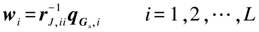
(2)
whererJ,iiis thei-th diagonal element ofRJ;qGa,iis thei-th column of the matrix containing the firstMrrows ofQGa, andQGaandRJare the QR decomposition ofGain which the diagonal elements of the upper-triangular matrixRJhave equal values[4]. In this way, information signals can be decoded sequentially using the sequential interference cancellation (SIC) procedure.
1.2 UCD+STBC scheme
In a closed-loop system, the receiver can feed back the precoding matrixFto the transmitter that is provided by UCD; meanwhile, the UCD block also produces a vectorwthat is used in the receiver for SIC-MMSE detection. A previously proposed combined UCD and STBC transceiver structure is shown in Fig.1[5, 12].
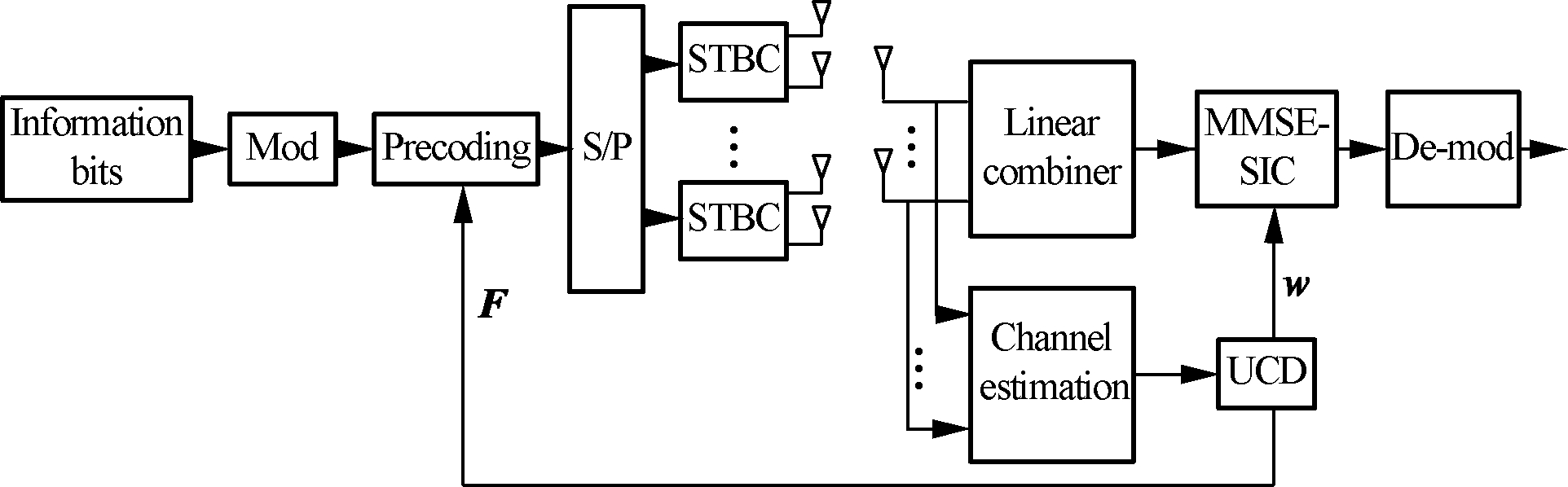
Fig.1 Conventional structure for UCD combined with STBC
The UCD+STBC configuration can be regarded as a form of joint coding, with STBC as the inner code and UCD as the outer code. Assuming 4 transmitting antennas and 2 receiving antennas, the block fading MIMO channel is

(3)
Using the 2×2 Alamouti coding matrix, four modulated information symbols (c1,c2,s1,s2) are transmitted in two consecutive time slots over 4 transmitting antennas, and the received signals during these two time slots are
r11=h11c1+h21c2+g11s1+g21s2+η11
(4)

(5)
As described in Ref.[12], the Alamouti channel matrix [H1 G1] for the first receiving antenna is given by
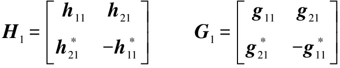
(6)
Similarly, we can obtain the received signals (r12,r22) during two time slots at the second receiving antenna as well as the Alamouti channel matrix [H2 G2] for the second receiving antenna. Then, the overall received signal vector is

(7)

From Fig.1, the effective channel with the UCD scheme is the Alamouti STBC channel with the linear combiner:
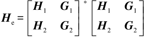
(8)
The transmit/receive relationship can be expressed as
y=HeFx+z
(9)
and then the SIC-MMSE detection procedure can be applied.
1.3 Proposed adaptive transceiver scheme
In our proposed adaptive system, we add the CSI feedback path to the precoder to select which coding method is to be used, i.e. UCD alone or UCD+STBC, as shown in Fig.2. In the simulations, we assume that a transceiver has 4 available antennas. When operating as a receiver, all 4 antennas are used in the UCD mode, while 2 antennas are used in the UCD+STBC mode.
Fig.3 presents Matlab simulation results under both UCD and UCD+STBC with BPSK, QPSK, 16-QAMand 64-QAM, using 500 channel trials and a 3 000 bit test length. From Fig.3, we can see that UCD+STBC achieves much better BER performance under poor channel conditions (e.g., SNR < 10 dB), while UCD performs well at a higher SNR. Thus, in the adaptive transceiver design, the UCD mode will be selected under good channel conditions, i.e. at a high SNR, in order to achieve a higher bit rate. On the other hand, UCD+STBC will be selected under poor channel conditions in order to maintain good BER performance at the cost of a reduced data rate.
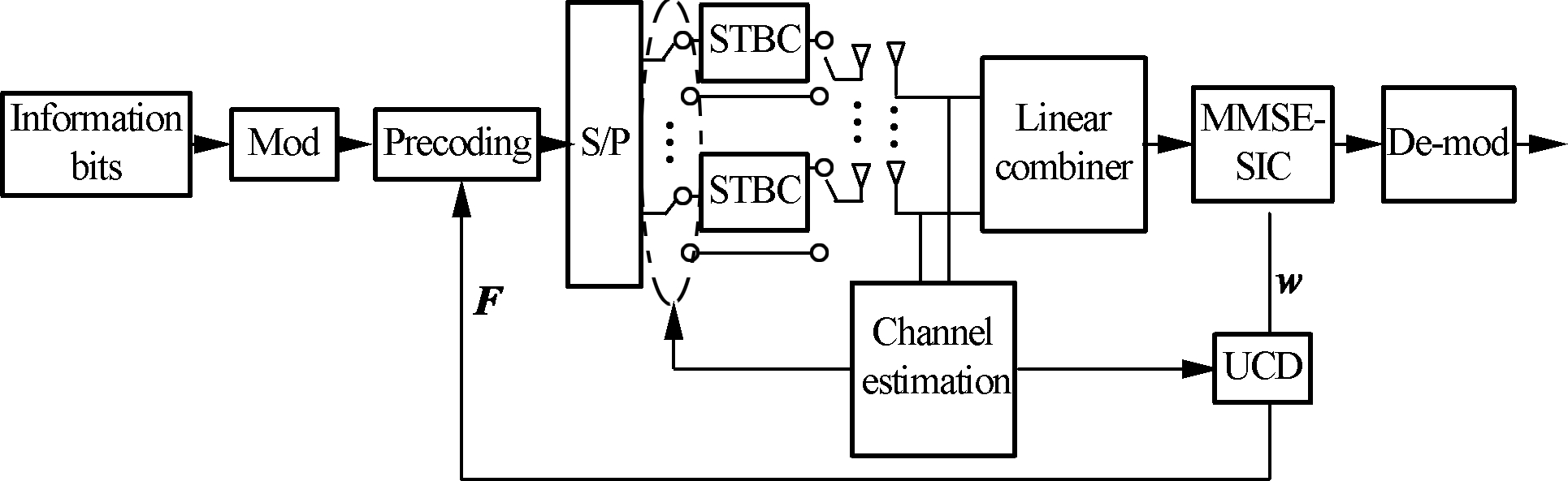
Fig.2 The proposed adaptive transceiver structure
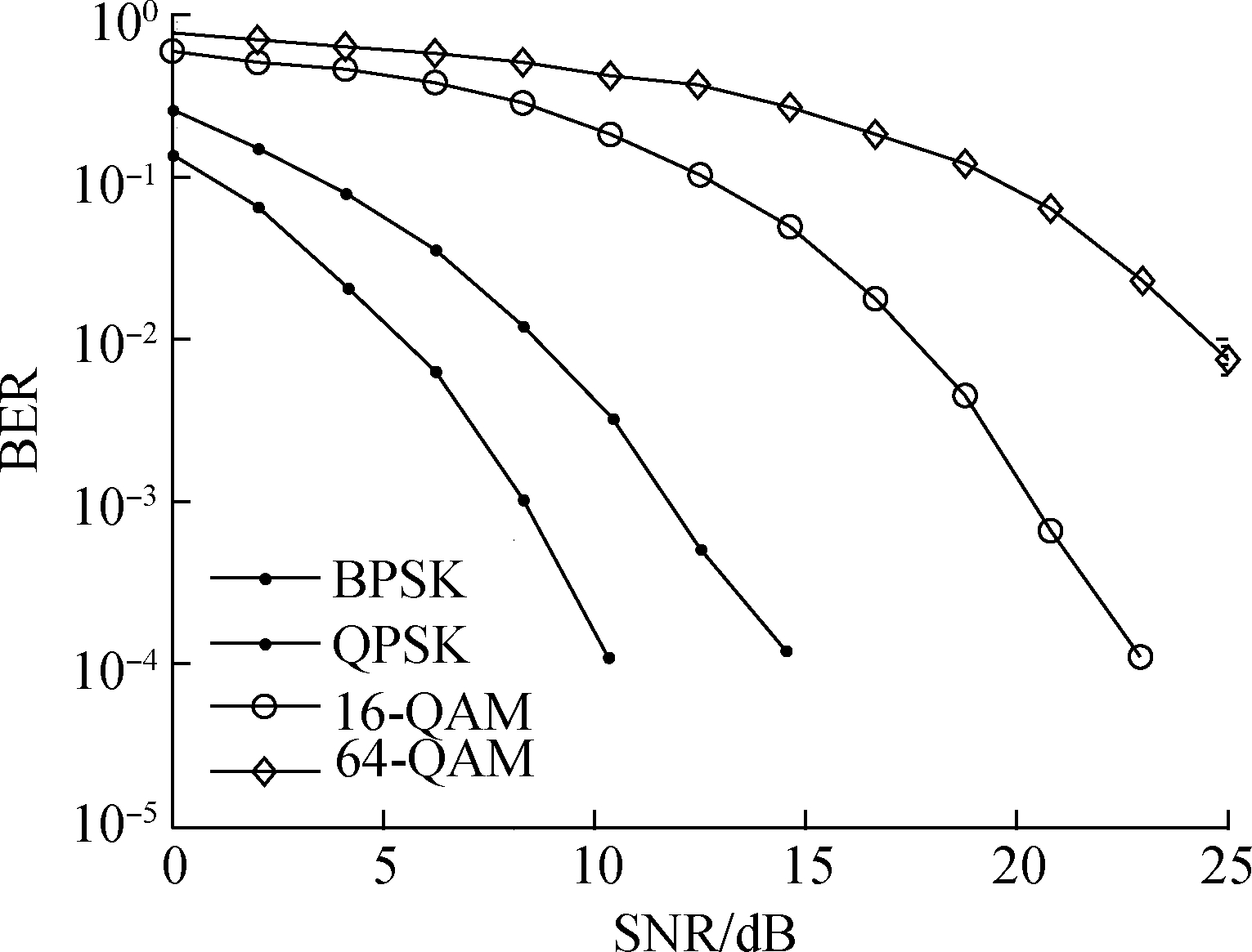
(a)
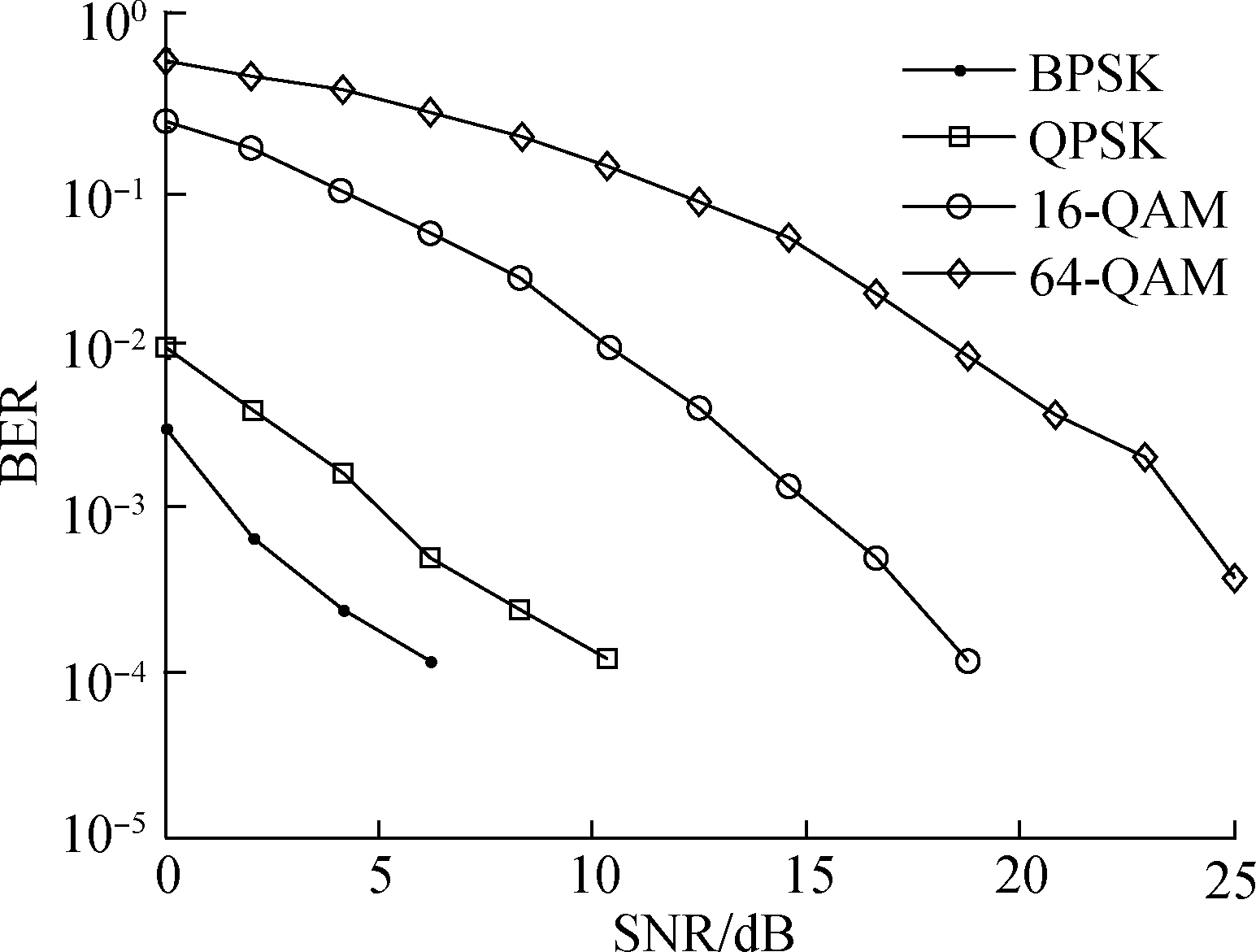
(b)Fig.3 Performance comparison of UCD and UCD+STBC. (a) Simulation result of UCD(Mr=4); (b) Simulation result of UCD+STBC(Mr=2)
Moreover, given a fixed transmission power, UCD and UCD+STBC both perform better when smaller constellation sizes are used (e.g., BPSK, QPSK, 16-QAM), particularly at a higher SNR, and they perform less well with larger constellations (e.g., 64-QAM), particularly in the case of UCD. Therefore, the adaptive selection between UCD and UCD+STBC based on the channel conditions will only be applied when smaller constellation sizes are used, while UCD+STBC will always be used with larger constellation sizes.
The implementation of the adaptive transceiver must achieve a suitable tradeoff between hardware flexibility and implementation complexity. In particular, it needs to be flexible enough to accommodate both UCD and UCD+STBC baseband processing, various sizes of channel matrices, and a range of possible constellations. In this section, we will demonstrate that a reconfigurable, heterogeneous baseband processing platform proposed in Ref.[8-11] can meet all of these requirements.
2.1 Review of reconfigurable execute units
In this subsection, we will briefly summarize three types of execution units (EUs)[8-11]which can be used to implement the adaptive transceiver architecture.
The reconfigurable arithmetic unit (RAU) shown in Fig.4 provides support for multiplication and addition operations. The circled portion in Fig.4 is the basic unit, which is referred to as an RAU slice. Each RAU slice provides a bypass data path from the slice output to the input of the 12-2 compressor (activated by a control signal “bp”), which is used to support the addition of successive values. Two adjacent slices can operate in a combine-mode (activated by a control signal “cb”) to complete onea×b+c×doperation, which releases the 4 input ports of a 4-2 compressor. Each RAU slice provides

Fig.4 Structure of the RAU slice
both 8 bit and 16 bit data widths, which are selected using a “div” control signal. Control signal “rv” indicates a revised value.
The reconfigurable logic unit (RLU) is designed to be the set of look-up table (LUT) elements. Each basic slice contains a 16×4 array of 4-1 LUTs, as shown in Fig.5(a). Since theciof each LUT are programmable, each LUT can support all bitwise Boolean operations through the specification of a truth table. There are two types of input/output modes, namely vertical and horizontal, which can be selected by a “mode” value.
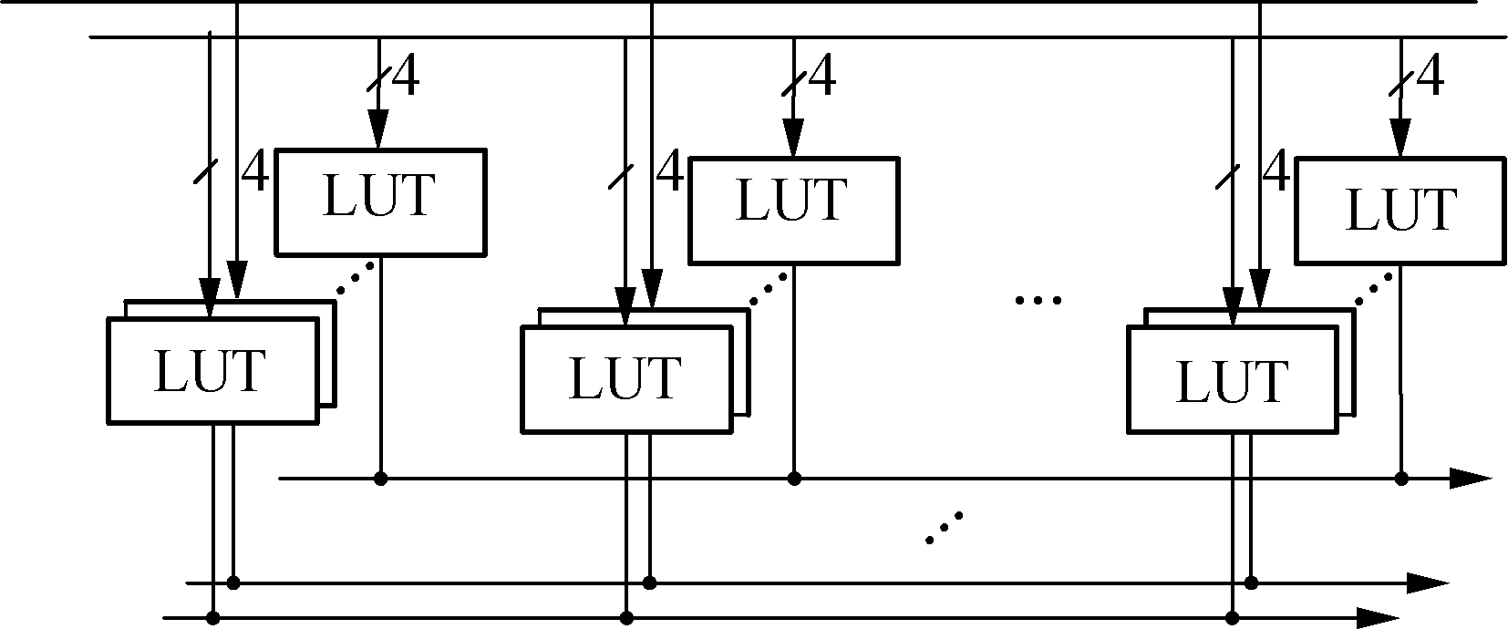
(a)
(b)Fig.5 Two types of EUs. (a) Structure of the RLU slice; (b) Structure of the AAU slice
The adder array unit (AAU) provides support for addition-intensive operations, such as data comparison and add-select-compare. Each AAU slice contains four sets of 8-bit adder/subtractors and two sets of 9-bit subtractors, as shown in Fig.5 (b). It has both 8-bit and 16-bit operation modes, and produces three output results:a0±a1,b0±b1and comparison. Note that ifa1=0 andb1=0,a0andb0will be compared; furthermore, ifb0=-a0, the comparison result will be the absolute value ofa0.
2.2 Implementation
In the adaptive transceiver, the UCD and UCD+STBC algorithms are required as well as a mechanism for flexibly switching between them. The information used to select between these two algorithms comes from the effective channel matrix,He, which requires conjugation and inversion operations[6]. While this can be implemented using an AAU and inverter logic, in this paper we consider it to be configuration information that is sent to the EUs by the top-level control system[9]in order to reduce the area of the processing core.
Therefore, only the precoding operation at the transmitter and the SIC-MMSE detection at the receiver need to be mapped onto the EUs. Here, we will use a 4×4 MIMO configuration with 16-QAM modulation as an illustrative example. From prior simulation studies done on closed-loop MIMO transceivers[13], it is found that using a 15-bit fixed point representation with a 5-bit integer part and a 10-bit fractional part can achieve good BER performance. As noted in the previous section, the EUs can be configured into 8-bit and 16-bit modes. Therefore, their 16-bit modes will be used. Fig.6 illustrates the complete system for precoding and SIC-MMSE detection.
2.3 Precoding
The precoding is performed as matrix multiplication, which involves multiply-with-add operations. As the operands are complex values, two multiplications can be done on 4 RAU slices. In total, 16 RAU slices operatingin the combine mode are used forx=Fis(i=1,2,…,n), wherenis the number of transmitted signals, and “cb” of the even-numbered RAU slices is set to be 1. After 4 clock cycles, two multiplications ofF×scan be completed.
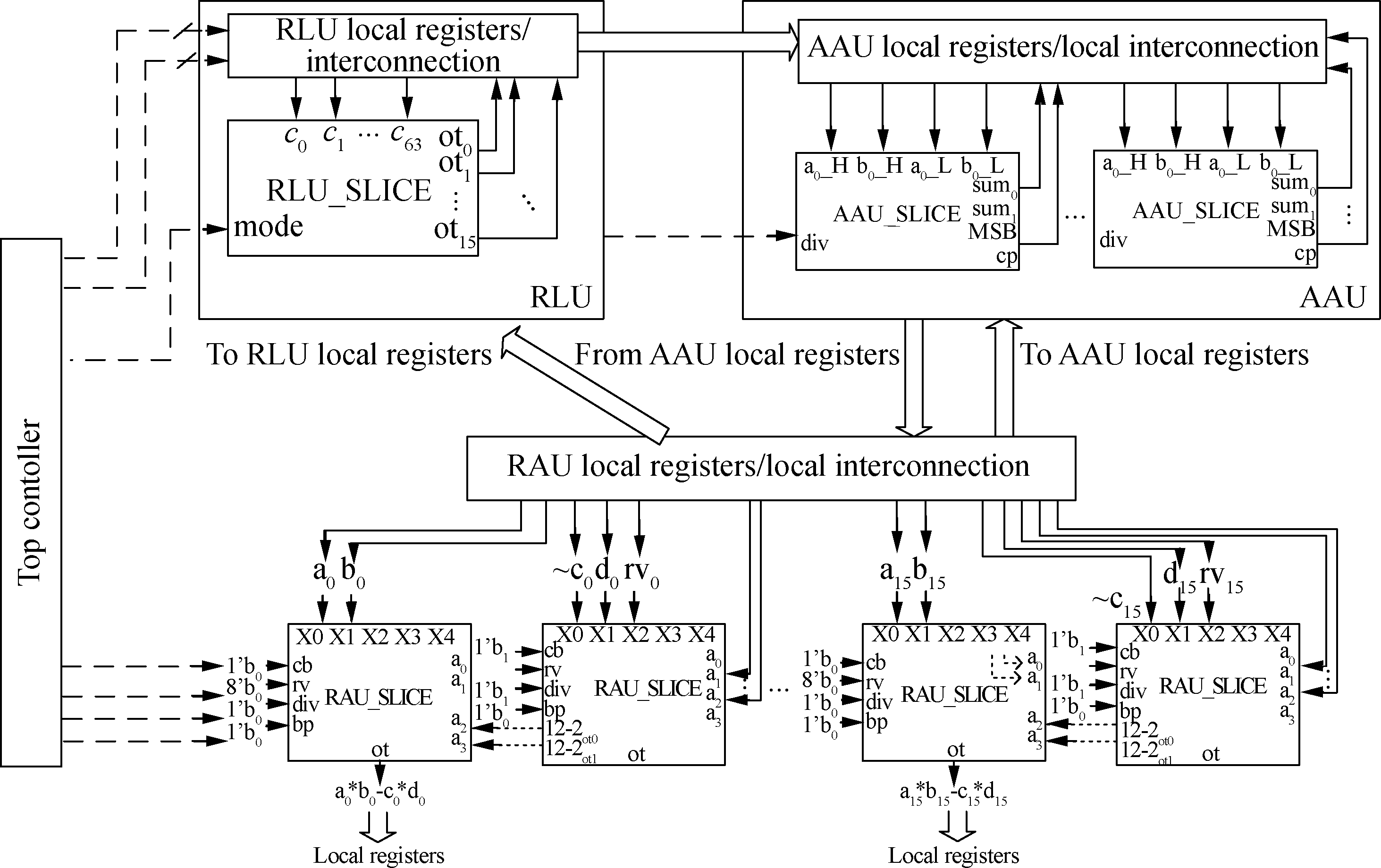
Fig.6 The configured system for pre-coding and MMSE detection
2.4 SIC-MMSE
SIC-MMSE is an iterative, sequential detection algorithm. It requires vector multiplications, constellation decisions and subtractions, as shown in Fig.7. Since the same computations are repeated in each iteration, the overall operation can be divided intonstages, where each stage reuses the same hardware blocks. We can also insert pipeline registers within each stage for further performance improvement.
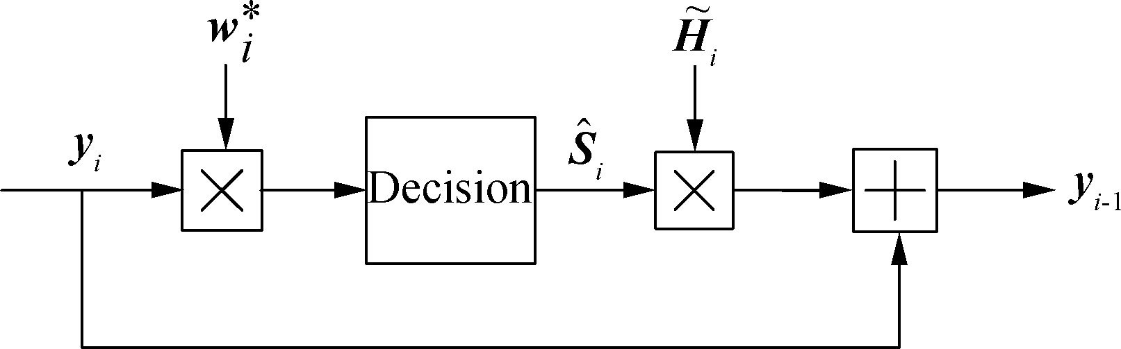
Fig.7 One computing stage for SIC-MMSE detection
In one stage of the computation, 32 RAU slices are needed to compute two vector multiplications. In addition, 1 RLU and 8 AAU slices are used to handle the demodulation of up to 64-QAM, and eight released 4-input adders in the RAU slices are used for vector subtraction.
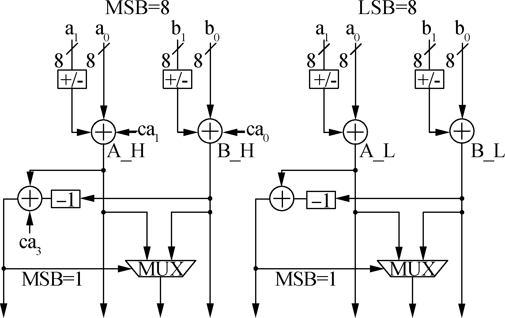
AAU slices process the comparison of an operand and a threshold. Taking 16-QAM as an example, the threshold can be set to be 0 and ±2. For design convenience, all AAU inputs are transformed into absolute values: if![]() <
<![]() , output=1; otherwise, output=0. Usinga0=
, output=1; otherwise, output=0. Usinga0=![]() ,a1=b0⨁b1,a2=1, we re-organize the truth table as shown in Tab.1, and the configured AAU slice is shown in Fig.8.
,a1=b0⨁b1,a2=1, we re-organize the truth table as shown in Tab.1, and the configured AAU slice is shown in Fig.8.
Tab.1 Input/output relationship of the LUTs
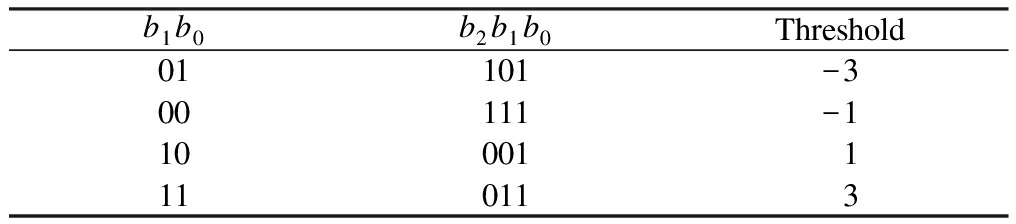
b1b0b2b1b0Threshold01101-300111-1100011110113
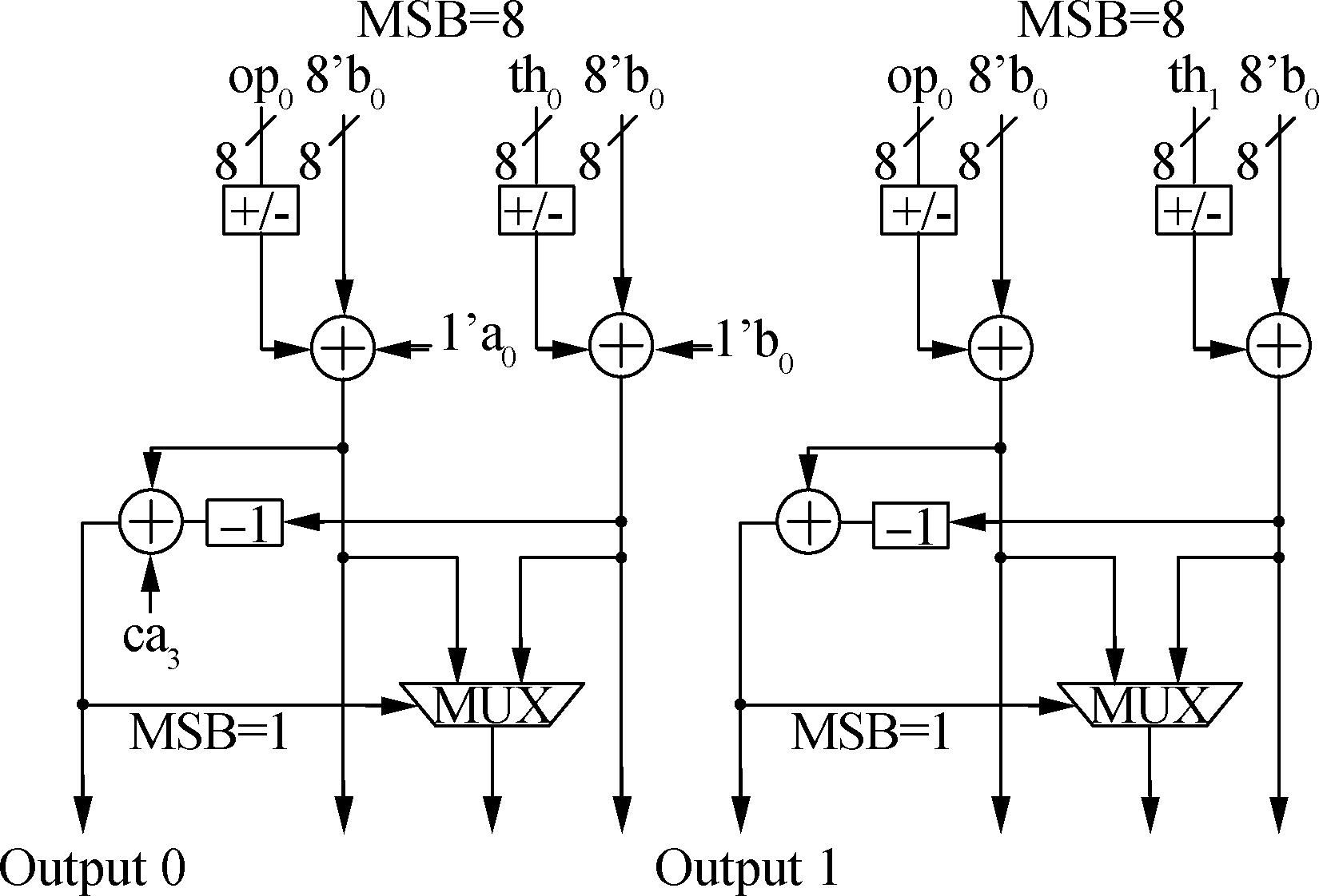
Fig.8 The configured AAU slice for MMSE detection
This truth table can be realized by 6 LUTs. The imaginary part follows the same procedure and requires the same LUT resources. For the maximum size constellation support, a total of 8 LUTs (1 RLU slice) are used for both the real and imaginary parts.
3.1 Analysis of simulation results
We performed Matlab simulations with a 4×4 antenna matrix for UCD, UCD+STBC and the proposed adaptive system, using BPSK, QPSK, 16-QAM and 64-QAM modulation. All channel taps are assumed to be zero mean, unit variance complex Gaussian random variables. The test data flows are 3 000 bits per sub-channel for BPSK and QPSK, 3 200 bits per sub-channel for 16-QAM, and 3 600 bits per sub-channel for 64-QAM. In all cases, 500 channel trials are used.
Fig.9 shows the performance comparison of UCD alone and the adaptive system under QPSK and 16-QAM modulations, respectively. The results indicate that the adaptive combination can give better performance than the UCD-only mode, particularly at a lower SNR (e.g., SNR < 10 dB). So, we obtain a good tradeoff between the data rate and performance with the adaptive system. With the smaller constellation sizes, the adaptive system will select the UCD-only mode at a high SNR, in order to achieve a higher bit rate. The UCD+STBC mode will be selected under the lower SNR conditions in order to maintain good BER performance at the cost of a reduced data rate.

(a)
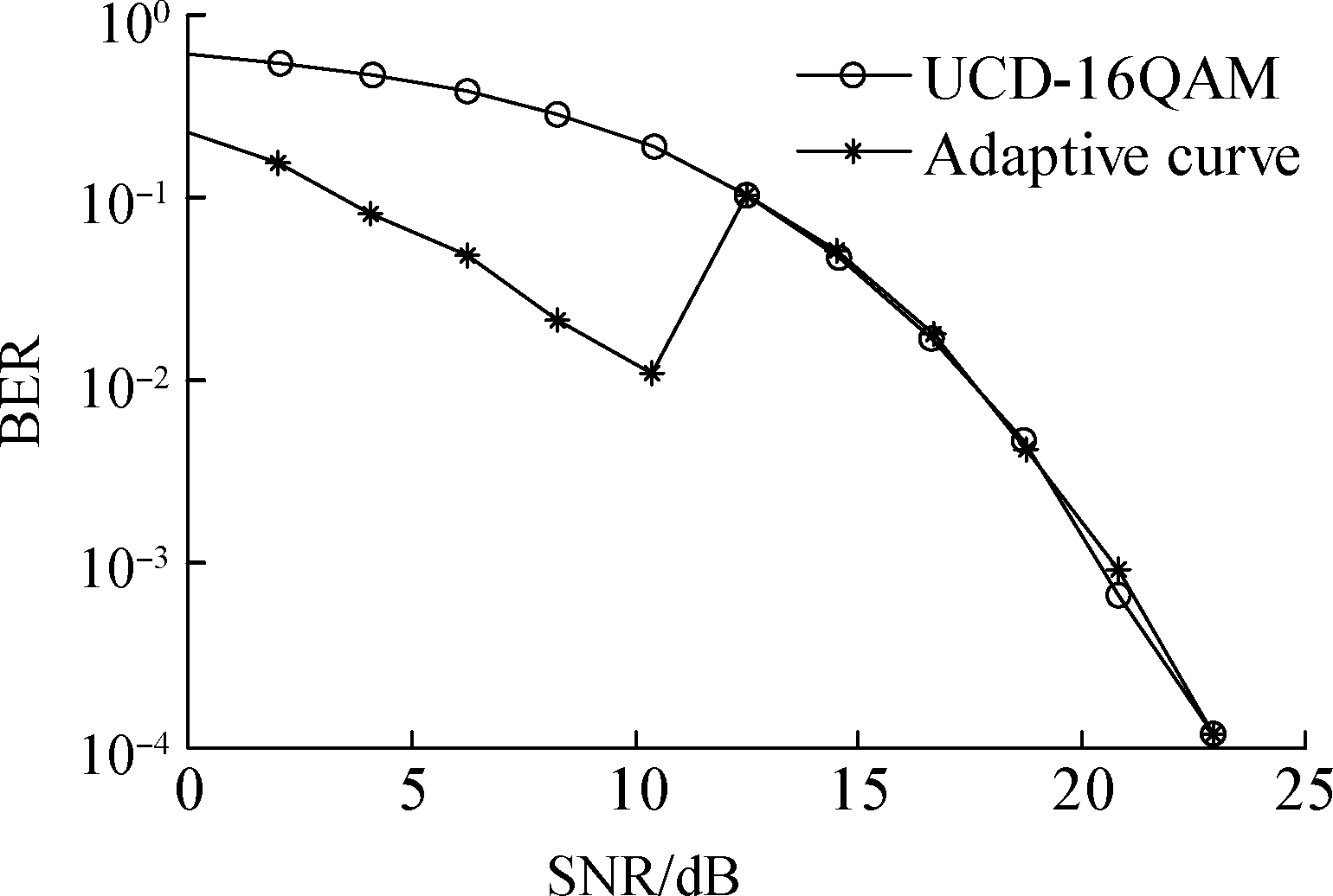
(b)Fig.9 Performance comparison of UCD and the adaptive system using different modulations. (a) UCD vs. the adaptive system using QPSK modulation; (b) UCD vs. the adaptive system using 16-QAM modulation
3.2 Hardware implementation cost
We use Matlab to calculate the precoder filterFand nulling vectorswi, which are then loaded onto the reconfigurable platform. Configurations of 2×2, 4×4 and 8×8 antenna sizes with 16-QAM modulation, and a 2×2 antenna matrix with 64-QAM were evaluated. The estimated post-layout areas of the EU slices are shown in Tab.2, which used UMC 0.18 ASIC technology and Xilinx xc4vlx Virtex-4 FPGA at 150 MHz[8].
Tab.2 Estimated area of each EU slice
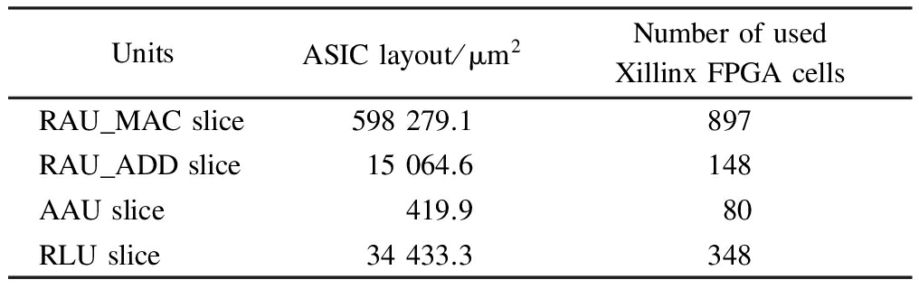
UnitsASIClayout/μm2NumberofusedXillinxFPGAcellsRAU_MACslice598279.1897RAU_ADDslice15064.6148AAUslice419.980RLUslice34433.3348
Tab.3 gives the number of EU slices needed for both precoding and SIC-MMSE sequential detection as well as the required number of clock cycles for coding/detecting one transmitted symbol (not counting the pipeline latency), as a function of the number of transmitting and receiving antennas. From Tab.3, we note that the required number of RAU_MAC slices and RAU_ADD slices grow linearly with the channel matrix size, while the number of AAU and RLU slices increase slightly with constellation size.
Tab.3 The required number of EU slices and clock cycle for 16-QAM and 64-QAM
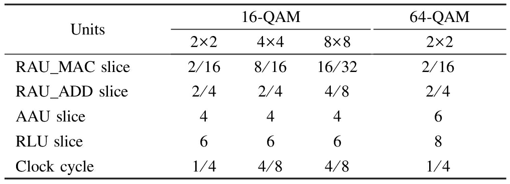
Units16⁃QAM2×24×48×864⁃QAM2×2RAU_MACslice2/168/1616/322/16RAU_ADDslice2/42/44/82/4AAUslice4446RLUslice6668Clockcycle1/44/84/81/4
1) A novel adaptive transceiver architecture is proposed, which flexibly combines both UCD and UCD+STBC technologies. In order to achieve higher overall performance, the CSI feedback path is added to the precoder to select between UCD-only and UCD+STBC modes.
2) With smaller constellation sizes, Matlab simulation results show that, the adaptive system will select the UCD-only mode under the higher SNR conditions in order to achieve a higher bit rate. The UCD+STBC mode will be selected under the lower SNR conditions (e.g., SNR < 10 dB) in order to maintain good BER performance at the cost of a reduced data rate.
3) The adaptive transceiver is efficiently implemented using a previously proposed reconfigurable hardware platform, and performance and area metrics for different configurations are determined. The results demonstrate that the required number of reconfigurable arithmetic unit slices increases linearly with the channel matrix size, while the number of adder array unit and reconfigurable logic unit slices increase slightly with the constellation size.
[1]Ahrens D A, Cano-Broncano F, Benavente-Peces C. Transmitter-side antennas correlation in SVD-assisted MIMO systems [C]//InternationalConferenceonE-businessandTelecommunications2013. Reykjavik, Iceland, 2013,456:402-417. DOI:10.1007/978-3-662-44788-8_24.
[2]Choi S, Lee C. Power allocation algorithms for GMD or UCD based joint transceiver designs [J].WirelessPersonalCommunications, 2014,79(1):105-118. DOI:10.1007/s11277-014-1844-6.
[3]Aleksandra P, Felip R P, Guillem F. A novel adaptive UCD-based MU-MIMO scheme for IEEE 802.11ac[C]//EuropeanWirelessConference2014. Barcelona, Spain, 2014:1-6.
[4]Aleksandra P, Felip R P, Guillem F. Adaptive uniform channel decomposition in MU-MIMO-OFDM: Application to IEEE 802.11ac [J].IEEETransactionsonWirelessCommunications, 2015,14(5):2896-2910. DOI:10.1109/TWC.2015.2396513.
[5]Darsena D, Gelli G, Paura L, et al. Blind channel shortening for space-time-frequency block coded MIMO-OFDM systems[J].IEEETransactionsonWirelessCommunications, 2012,11(3): 1022-1033. DOI:10.1109/twc.2012.010312.110126.
[6]Xu W Y, Bao Y Q, Yu X B. Precoding design for STBC-MIMO system with imperfect feedback in spatially correlated Rayleigh channel [J].ElectronicsLetters, 2014,50(22):1606-1607. DOI:10.1049/el.2014.1621.
[7]Palomar D P, Cioffi J M, Lagunas M A. Joint Tx-Rx beamforming design for multicarrier MIMO channels: A unified framework for convex optimization [J].IEEETransactionsonSignalProcessing, 2003,51(9):2381-2401. DOI:10.1109/tsp.2003.815393.
[8]Lu W, Zhao S, Lu C, et al. A heterogeneous reconfigurable baseband architecture for wireless LAN transceivers [C]//2008IEEEInternationalConferenceonElectro/InformationTechnology. Ames, USA, 2008:284-288.
[9]Zhao S, Lu W, Zhou X, et al. Implementations of FFT and STBD for MIMO-OFDM on a reconfigurable baseband platform[J].IEICETransactionsonInformationandSystems, 2010,93(4): 811-821. DOI:10.1587/transinf.e93.d.811.
[10]Lu W Q, Zhao S, Zhou X F, et al. Reconfigurable baseband processing architecture for communication[J].IETComputers&DigitalTechniques, 2011,5(1): 63-72. DOI:10.1049/iet-cdt.2009.0121.
[11]Zhou X, Zhao S, Lu W, et al. Reconfigurable baseband processing platform for communication systems[C]//2008IEEEAsiaPacificConferenceonCircuitsandSystems. Macau, China, 2008.DOI:10.1109/apccas.2008.4745952.
[12]Lü L, Zhang Z P. Research of a kind of adaptive MIMO transmission and detection[C]//InternationalConferenceonCommunications,CircuitsandSystems. Xiamen, China, 2008: 212-215.
[13]Wang J, Sobelman G E. Reconfigurable MIMO transceiver design using the tunable channel decomposition[J].Signals,Systems&Computers, 2010,45(2):381-384.
References
摘要:为解决复合天线通信系统使用均匀信道分解(UCD)的预编码/空时分组编码(STBC)技术改善系统误码性能的同时降低数据传输速率的问题,提出一种新的包含UCD和UCD+STBC技术的自适应收发器架构.通过增加信道状态信息(CSI)反馈回路至预编码器,实现系统采用单独的UCD或UCD+STBC编码工作模式的选择.Matlab仿真结果显示,在较小星座图条件下,自适应收发器架构在高信噪比状态时,通过选择UCD工作模式,保证系统具有较高的数据传输速率.在低信噪比状态时(如信噪比小于10 dB),系统通过选择UCD+STBC工作模式,以降低数据传输速率为代价保证系统具有较好的误码率性能.该体系结构通过UMC 0.18 ASIC工艺和Xilinx xc4vlx Virtex-4 FPGA在工作频率150 MHz条件下实现并验证.结果表明,所需的可重构算术单元与信道矩阵大小成线性增长,而加阵列单元和可重构逻辑单元的数目随星座图大小的增加而略有增加.
关键词:预编码;均匀信道分解(UCD);空时分组编码(STBC);自适应收发器;基带架构重构
中图分类号:TN929.5
![]()
JournalofSoutheastUniversity(EnglishEdition) Vol.33,No.3,pp.273⁃276Sept.2017 ISSN1003—7985
DOI:10.3969/j.issn.1003-7985.2017.03.003
Foundationitems:The National Natural Science Foundation of China (No.61376025), the Industry-Academic Joint Technological Innovations FundProject of Jiangsu (No.BY2013003-11), the Scientific Innovation Research of College Graduates in Jiangsu Province (No.KYLX_0273).< class="emphasis_bold">Citation
Citation::Ye Yunfei, Wu Ning, Ge Fen, et al. Design of an adaptive precoding/STBC baseband transceiver on a reconfigurable architecture[J].Journal of Southeast University (English Edition),2017,33(3):266-272.
DOI:10.3969/j.issn.1003-7985.2017.03.003.