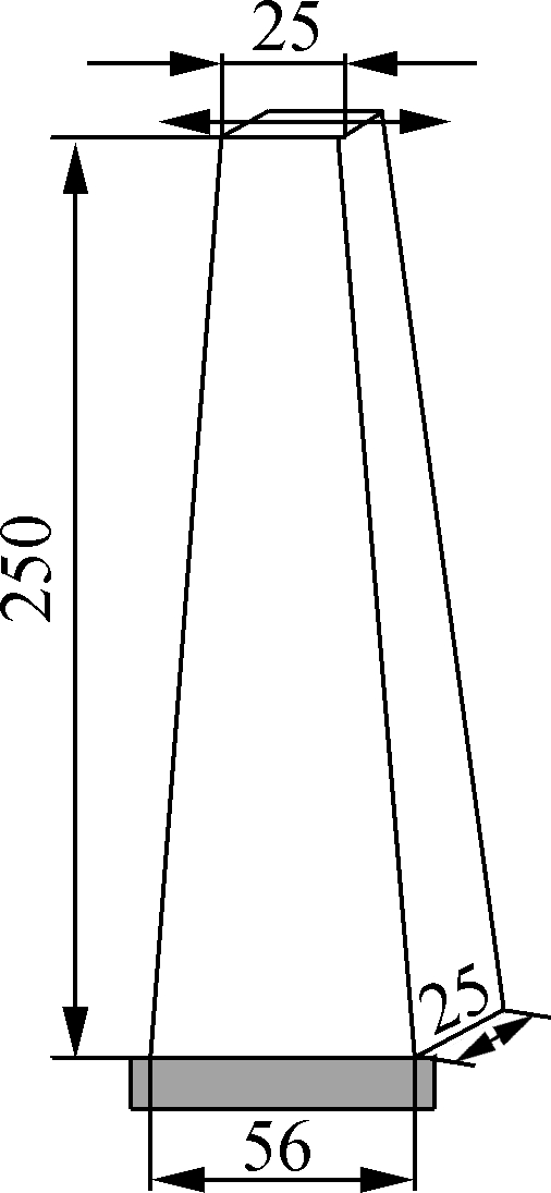
Fig.1 Two-point trapezoidal beam(unit: mm)
Abstract:In order to investigate the fatigue performance of French high modulus asphalt concrete and the correlation between Burger’s parameters and fatigue life, the virtual model of asphalt mixture trapezoidal specimen in the two-point bending fatigue test was constructed in discrement element software PFC3D. The initial stiffness and the maximum stress when the specimen reached fatigue were calculated. Through the comparison between virtual and single field fatigue test curves, the credibility of simulation in DEM was verified. Then, the impacts of top controlled displacement and Burger’s parameters (E1,E2,η1,η2) on the fatigue life of the specimen were explored. The simulation results indicate that the maximum stress increases with the increase in the top controlled displacement. With the increase ofE1and the decrease ofE2in Burger’s model, the modulus of the asphalt binder increases, and the fatigue performance of the asphalt mixture enhances.η1andη2have limited influence on fatigue life compared withE1andE2.
Keywords:high modulus asphalt concrete; numerical simulation; Burger’s parameters; fatigue life
High modulus asphalt binder (HMAB) with a penetration grade less than 25 (0.1 mm) at 25 ℃has played a pivotal role in the French asphalt mixture design method[1]. After being developed in the France for over 30 years, it was introduced to the United Kingdom, South Africa and Australia[2].The superiority of high modulus asphalt concrete (HMAC) mainly lies in its better performance in deformation, fatigue and moisture resistance than base asphalt[3].
Research conducted by Corté[4]in 2001 indicated that HMAC showed better anti-fatigue performance and an increment in strain after fatigue failure. Hernández[5]reported that high modulus asphalt retained good resistance to fatigue and rutting. Airey et al.[6]evaluated the aging and moisture induced damage resistance of HMAC through laboratory tests. Previous studies proved the engineering potentiality of this material but failed to reveal the mechanism for improving fatigue performance[3, 7-8].Thus, numerical simulations based on the finite element method (FEM) were conducted to investigate the mechanical responses and road performance of this material. Zhang et al.[9]simulated the distribution of maximum deflection and shear stress for HMAC pavement under the standard axle load in 2012.Zheng et al.[10]evaluated the permanent deformation of HMAC using the finite element method. However, the assumption of homogeneity of asphalt concrete in FEM was not able to accurately reflect the material properties.
Compared with FEM, the discrete element method (DEM) is superior for investigating the micromechanics asphalt mixture and in describing the dynamics of the assembly of aggregates and asphalt binder. In 2001, Ullidtz[11]simulated the permanent deformation and brittle damage of asphalt mixture after repeated loading using DEM. Buttlar et al.[12]investigated the indirect shear test by conducting a virtual test on the discrete element model. Liu et al.[13]tested and verified the effectiveness of Burger’s model in simulating the mechanical behaviors of asphalt. Chen et al.[14]studied the fatigue test of asphalt mixture using PFC and verified the modeling method through the comparison of simulation and laboratory results. Thus, DEM is selected to investigate the fatigue performance of HMAC.
In this paper, a virtual three-dimensional trapezoidal specimen model was constructed in PFC3D, a particle flow software based on DEM. Then, Burger’s model was applied to describe the viscoelastic properties of the asphalt binder. The virtual model was verified through the comparison with laboratory fatigue test results. Then, the fatigue performance of the virtual specimen was evaluated by verified top controlled displacement and Burger’s model parameters. As a result, the connection between the fatigue performance of HMAC and the viscoelastic properties of the asphalt binder was established. This study provides a new insight and theoretical basis for improving the fatigue performance of asphalt mixture using HMAC design.
1.1 Virtual 3D trapezoidal specimen
Two-point trapezoidal beam fatigue test is widely adopted in Europe to evaluate the fatigue performance of asphalt mixture. According to European standard BS EN 12697-24[15], the test is conducted in the controlled displacement mode (see Fig.1).In the test, the base surface of the specimen is fixed to the device platform using epoxy resin. Simultaneously, constant amplitude sinusoidal deflectionDshown in Fig.2 is exerted on the top surface of the specimen horizontally. Fatigue failure is reached when the recorded force on the top surface decreases to a certain percentage of the initial value.
Fig.1 Two-point trapezoidal beam(unit: mm)
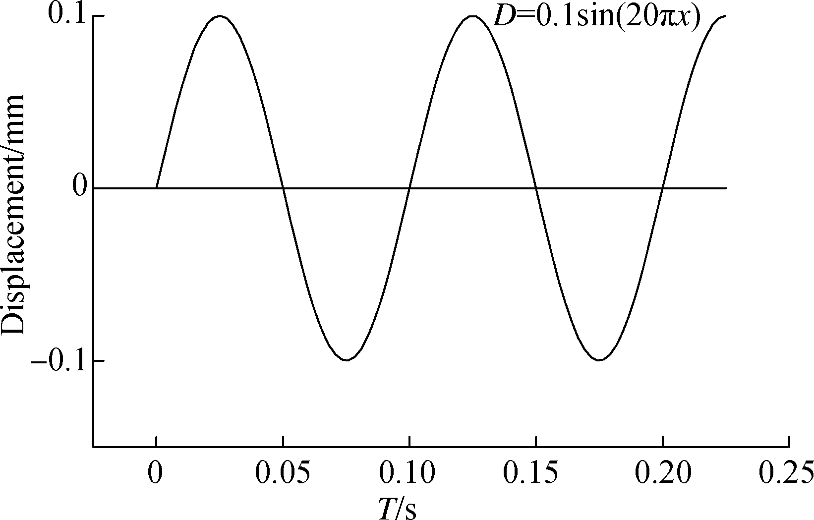
Fig.2 Applied sinusoidal displacement
Asphalt mixture is a three-phase composite material composed of the asphalt binder, aggregates and voids. Since fine aggregates and mineral fines have minor contribution to the mixture’s strength and move with the asphalt binder under external force, the aggregates smaller than 4 mm, mineral fines and asphalt binder are assumed to be homogeneous discrete elements in PFC.
Based on the asphalt mixture composition shown in Tab.1[16], coarse aggregates, asphalt binder and voids were generated in PFC3D. The asphalt content was 6.4%, and air voids were 4%. The entire process of generating a virtual three-dimensional trapezoidal specimen of asphalt mixture in PFC is shown in Fig.3. In the first step, coarse aggregates were generated as aggregate balls without overlapping in the trapezoidal volume (see Fig.3(a)). Then, 1 mm ball units were created evenly in the whole trapezoidal volume, overlaying the space of the aggregates (see Fig.3(b)). These balls represent the asphalt binder and 1 mm was proved to be the most suitable size[14]. Afterwards, irregular polyhedron aggregates were created by applying the clumps generating algorithm in PFC based on the position information in Fig.3(a). The algorithm considered the center of each aggregate ball to be the centroid of the external cube, and several random planes were generated to cut the hexahedral to obtain irregular polyhedron aggregate. The homogeneous 1 mm balls included in the polyhedron aggregates were regarded as part of an aggregate element, and then were cumulated together as “clump” unit in PFC. There was no contact among balls in the clump, which were a suitable replacement for the aggregates. Then, the aggregates generated in Fig.3(a)were deleted, and thus there was no overlapping in the three-dimensional specimen. The eventually obtained virtual specimen shown in Fig.3(c)contained two phases: aggregates represented by clumps and asphalt binder represented by 1 mm ball units. In order to meet the requirements of air voids in the asphalt mixture, the numbers of ball units calculated according to the volume fraction were deleted at random. It was assumed that all the air voids in the virtual specimen were distributed randomly.
Tab.1 Asphalt mixture gradation
Sievesize/mm46.31014Percentage/%31.55576100
![]() (a)
(a) ![]() (b)
(b) ![]() (c)
(c)
Fig.3 Construction of the virtual trapezoidal specimen in PFC.(a) Coarse aggregates; (b) Ball units; (c) Clumps and ball units
1.2 Microscopic contact parameters
Four types of microscopic contact parameters are taken into consideration in the following models: the elastic contact and point bond model among the interior units of aggregates, the rheological and parallel bond model among the interior units of asphalt binder, the rheological and parallel bond model between aggregates and asphalt binder, and the elastic contact and parallel bond model between different aggregates. As the “clump” was applied to describe the aggregates and the force inside the clump was ignored, contact among the interior units of aggregates was also ignored in this paper. The contact model between the aggregates and asphalt binder is equivalent to the contact among the interior units of asphalt binder, due to the binder film covering the aggregates.
The physical properties of aggregates have a high stability, and thus the elastic modulus and Poisson’s ratio can be chosen as the constant. The parallel bond model contains normal and tangent stiffness parametersKnandKs, which are only concerned with the radius of discrete units. Corresponding microscopic parameters are shown in Tab.2.
Tab.2 Microscopic contact model parameters of aggregate
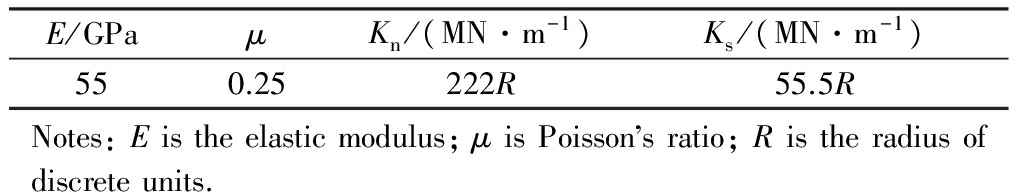
E/GPaμKn/(MN·m-1)Ks/(MN·m-1)550.25222R55.5RNotes:Eistheelasticmodulus;μisPoissonsratio;Ristheradiusofdiscreteunits.
The rheological contact model has an important role in describing the mechanical properties of asphalt binder. Burger’s model was chosen as a good approximation for macroscopic mechanics. The creep compliance of the model is expressed as
J(t)=![]() +
+![]() +
+![]()
(1)
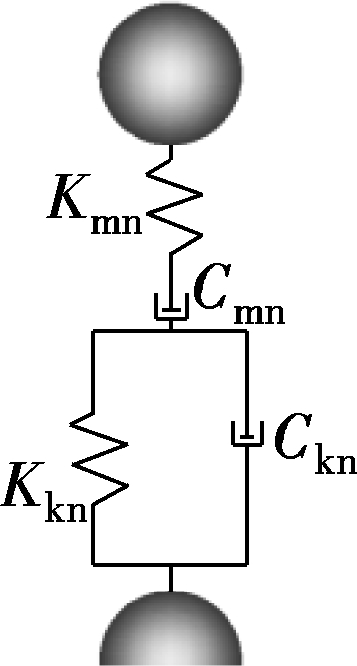
The corresponding microcosmic Burger’s model in PFC is equivalent to the viscoelastic beam between two elements with a radius ofR1andR2. The equivalent beam length isL=R1+R2. The microscopic Burger’s model can be represented in normal and tangent directions individually in Fig.4[17].Cmn,Kmn,Ckn,Kkn,Cms,Kms,Cks, andKksare the microscopic Burger’s parameters.
(a)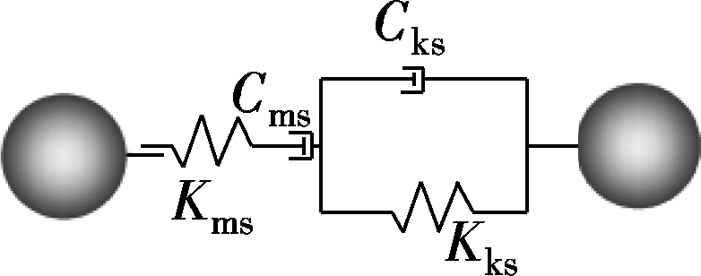
(b)
Fig.4 Microscopic Burger’s model.(a)Normal; (b)Tangent
Supposing that the micro-contact force isfn, the relationship betweenfnand macro-contact stressσisfn=σΑ, whereA=L2is the cross sectional area of the equivalent beam. The normal micro-contact force can be expressed as

(2)
whereεmn,εk,εmkare the corresponding strains for the mechanical elements in Burger’s model.
The macro-contact stress can be expressed as

(3)
Combining Eqs. (2), (3) andfn=αA, the normal parameters of microscopic Burger’s model can be written as
Cmn=η1L, Kmn=E1L
Ckm=η2L, Kkn=E2L
(4)
Considering that the relationship between elastic modulusEand shear modulus isG=![]() , the tangent parameters of microscopic Burger’s model can be written as
, the tangent parameters of microscopic Burger’s model can be written as
Kks=![]() L,Cks=
L,Cks=![]() L
L
Kms=![]() L,Cms=
L,Cms=![]() L
L
(5)
The microscopic Burger’s model parameters can be selected once the macroscopic Burger’s model is determined. Komba et al.[18]performed the laboratory dynamic modulus testing for hot-mix asphalt with a 20/30 penetration grade binder, which satisfied the HMAB definition. Thus, the microscopic Burger’s model is determined according to the relationship between micro and macro parameters. The microscopic rheological parameters of asphalt mixture are shown in Tab.3.
Tab.3 Microscopic contact model parameters of asphalt
ParameterCmnKmnCknKknCmsKmsCksKksValue267852L17034L184L31016L107141L6814L74L12406L
Based on the model parameters above, a two-point trapezoidal fatigue test was simulated in PFC. The test was carried out with a top displacement amplitude of 0.1 mm and loading frequency of 10 Hz. Applied force on the top of the trapezoidal specimen was recorded every 10 cycles. The field two-point trapezoidal fatigue test was conducted and the loading force was recorded as well[16].
According to the conventional bending theory, the stiffness modulus of HMAC in two-point bending fatigue tests has the following expression[19]:
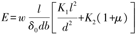
(6)
wherewis the applied load, kN;lis the length of the specimen, m;δ0is the deflection at the top, mm;dis the top width, m;bis the thickness of the specimen, m;K1andK2are the coefficients depending on the geometry of the specimen,K1=0.370 64,K2=1.144 02.
Based on the recorded loading force in the simulation and field tests, the stiffness variations of trapezoidal specimen are calculated and plotted in Fig.5.Observing thetwo curves, an identical tendency is detected among the simulation results and realistic results. The comparison can confirm the validity of the microscopic parameters adopted in the virtual DEM model.
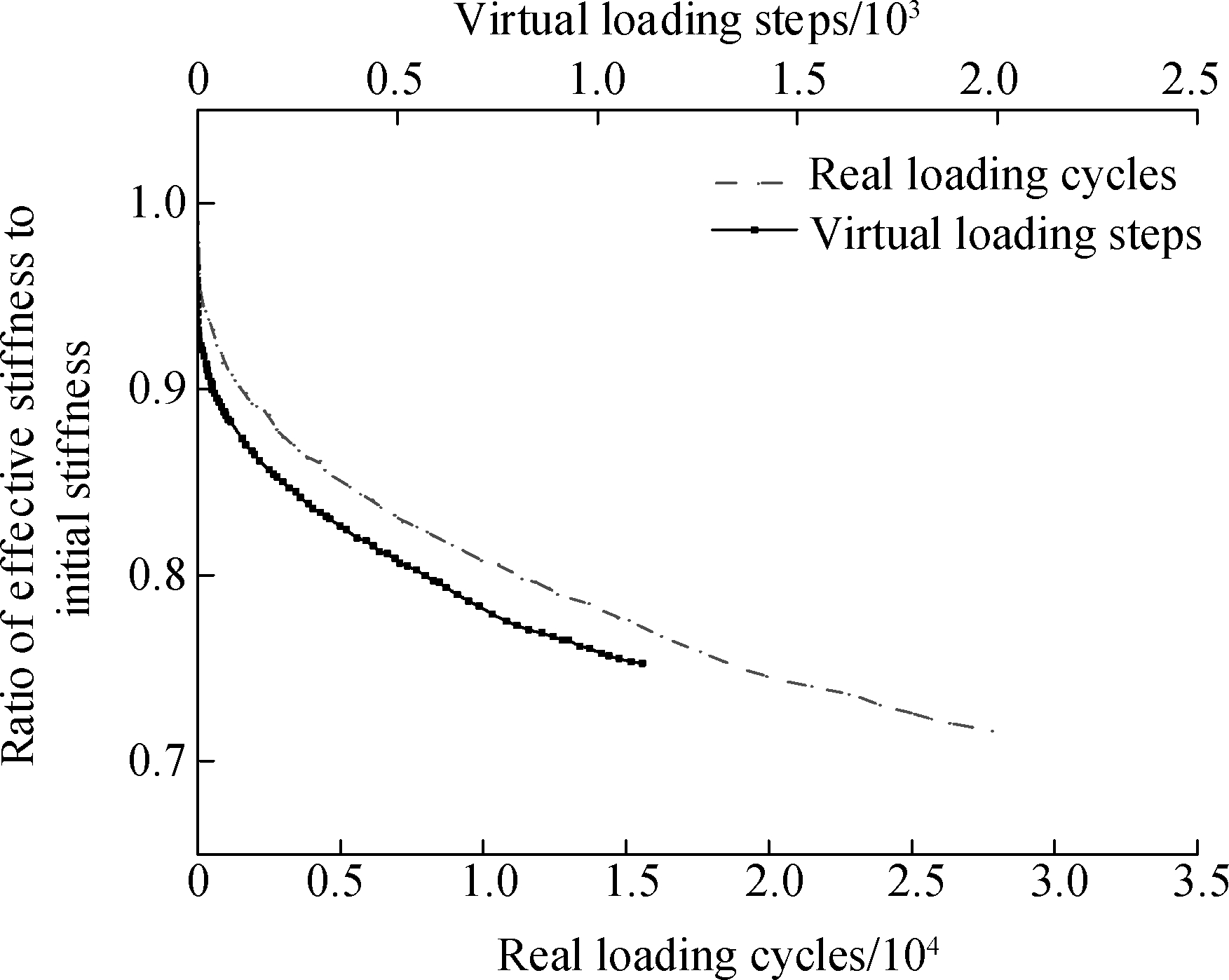
Fig.5 Variation of stiffness in the field test and simulation test
2.1 Virtual fatigue test realized in PFC
In the virtual model, the position of the base layer of ball units in the trapezoid specimen was fixed. The constant amplitude sinusoidal deflection applied to the top layer horizontally was changed to 1 mm. Loading frequency was chosen as 10 Hz, which meant that loading time was around 0.016 s. The maximum stress inside the specimen is recorded utilizing serro-mechanism.
In the field bending fatigue failure, fatigue failure is reached when the force on the top of the specimen declines to 50% of the initial force. However, it is time consuming to adopt that criteria. Thus, it was considered that the specimen fails when the force on the top of the specimen declines to 60% of the initial force. The simulation result is of the same significance as it reflects the same tendency of the fatigue life variation when the parameters change.
As can be seen from Fig.6,the applied force on the specimen dropped rapidly, and then gradually tended to be smooth with cycling. As the crack did not occur in the deflection-control fatigue test, the decrease of the maximum stress follows a similar tendency.
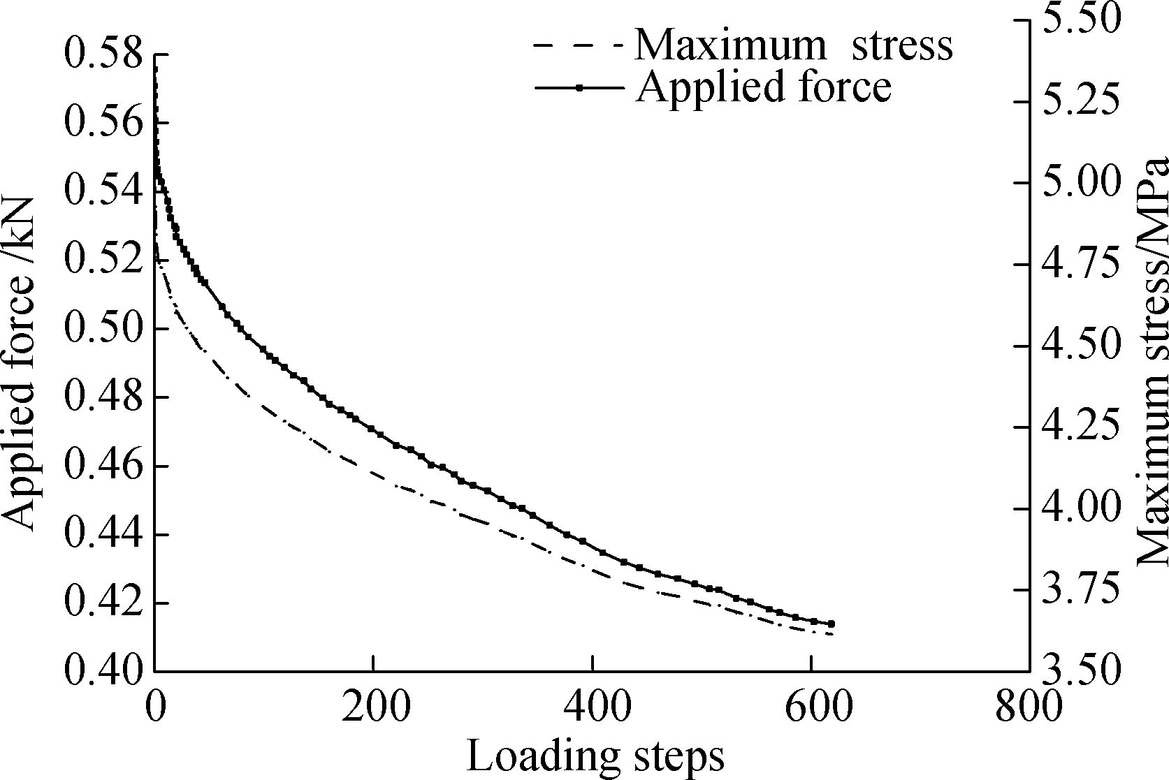
Fig.6 Applied force and maximum stress vs. loading steps
2.2 Effect of top displacement on fatigue life
In the simulations, by altering the displacement applied to the top of the specimen, with the frequency being maintained, the values of fatigue life and the maximum stresses were observed. The initial stiffness was calculated by Eq.(6).
Fig.7 shows that when the displacement increases, the fatigue life decreases, and the maximum stress increases. It can be seen that the variation of fatigue life is nearly linear with deflection after the logarithmic coordinate is applied. From Eq.(6), it can be seen that when the stiffness remains, the applied force linearly increases with deflection increasing. This is related to the increasing maximum stress in the specimen. The multiples of deflection amplification are related to the maximum stress increasing multiples. If the applied deflection is increased tenfold, the maximum stress increases approximately tenfold at the same time. Ignoring the decimal omission due to the scientific notation, this can be attributed to the fact that the maximum strain in the specimen is linear with macro deflection, and the strain is related to the applied deflection.
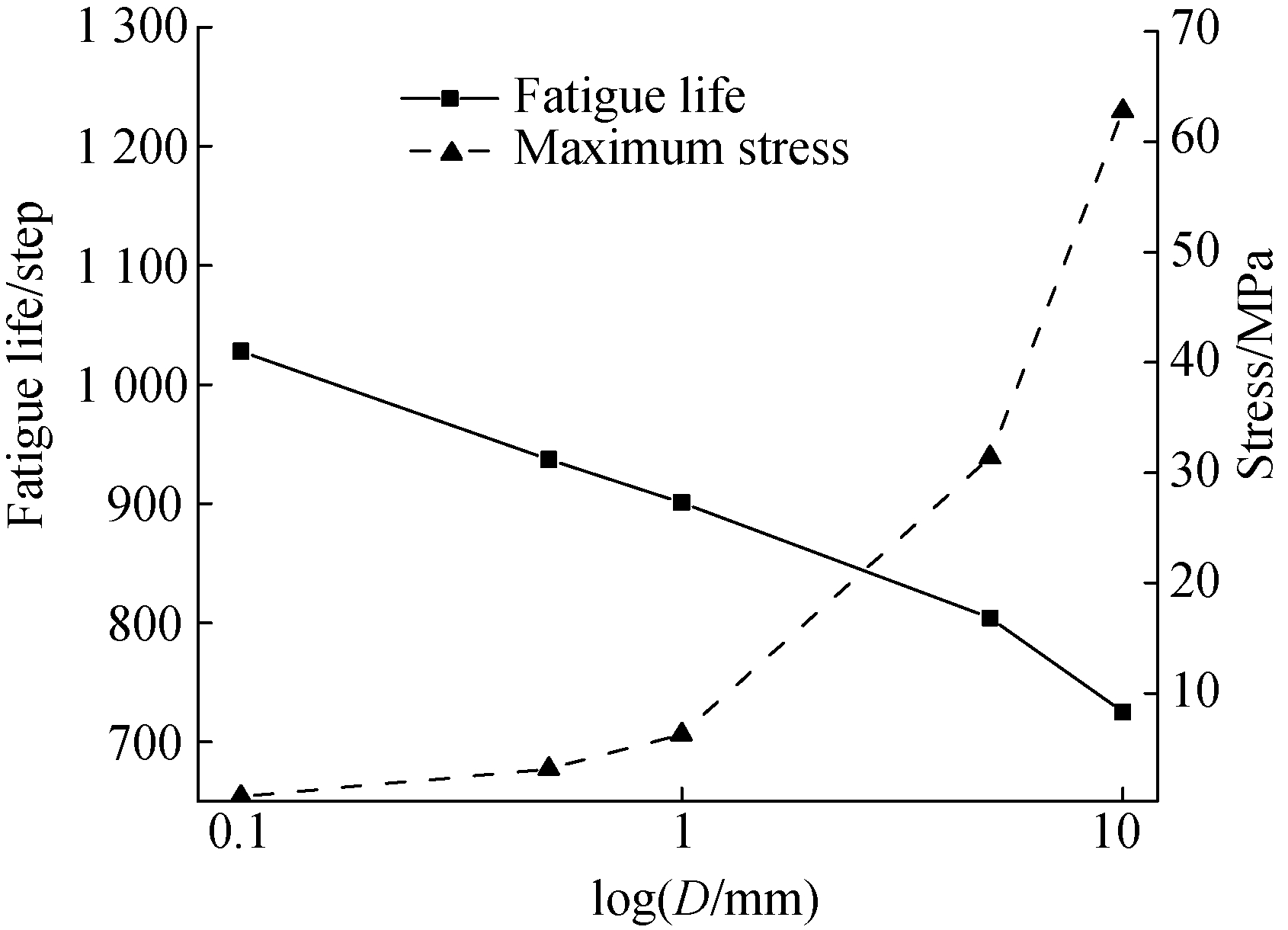
Fig.7 Variations of fatigue life and stiffness vs. controlled deflection
The stiffness remains constant in the test, which is around 4 GPa, and it is independent of applied deflection.
2.3 Effects of macroscopic parameters on fatigue life
As the viscoelastic property of the asphalt binder has an important role in enhancing the modulus of asphalt mixture, it is necessary to investigate the effects of rheological parameters to provide a theoretical basis for improving the fatigue performance of the asphalt mixture.
The viscoelastic property of asphalt mixture is expressed by Burger’s model in this paper, and macroscopic mechanical parameters (E1,E2,η1,η2) in the model have a close correspondence with microscopic parameters (Cmn,Kmn,Ckn,Kkn,Cms,Kms,Cks,Kks) as above. Thus, the determination ofE1,E2,η1,η2is important for reflecting material mechanical properties.
When different grades of asphalt are selected in the mixture, usually most of macroscopic parameters are changed, particularly when high modulus asphalt mixture is taken into analysis. It is discovered thatE1tends to increase andE2tends to decrease when the asphalt modulus rises and penetration drops. In order to investigate the influence of macroscopic parameters (E1,E2,η1,η2) in Burger’s model on the fatigue life of asphalt mixture, the method of control variables is applied in this part. The maximum displacement on the top of the specimen is 0.1 mm, and the frequency applied is 10 Hz.
Based on the simulation results in Fig.8, the fatigue life of the asphalt mixture increases whenE1increases. This shows high degree of consistency with field test results. It is found from the simulation that the maximum stress increases with the increase ofE1. And, according to Eq.(6), the initial stiffness increases from 6 800 to 10 220 MPa with the increase ofE1. The results indicate a completely different trend of the variation ofE2compared withE1. It explained why the fatigue life and maximum stress decreases with the increase ofE2,and the calculated initial stiffness drops from 4 445 to 3 625 MPa, which corresponds to the previous study[20]. The effects ofE1andE2are opposite, and the high modulus of HMAC can be attributed to the increase ofE1.
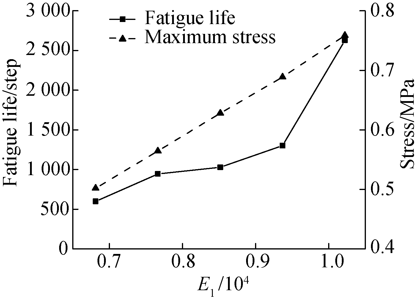
(a)
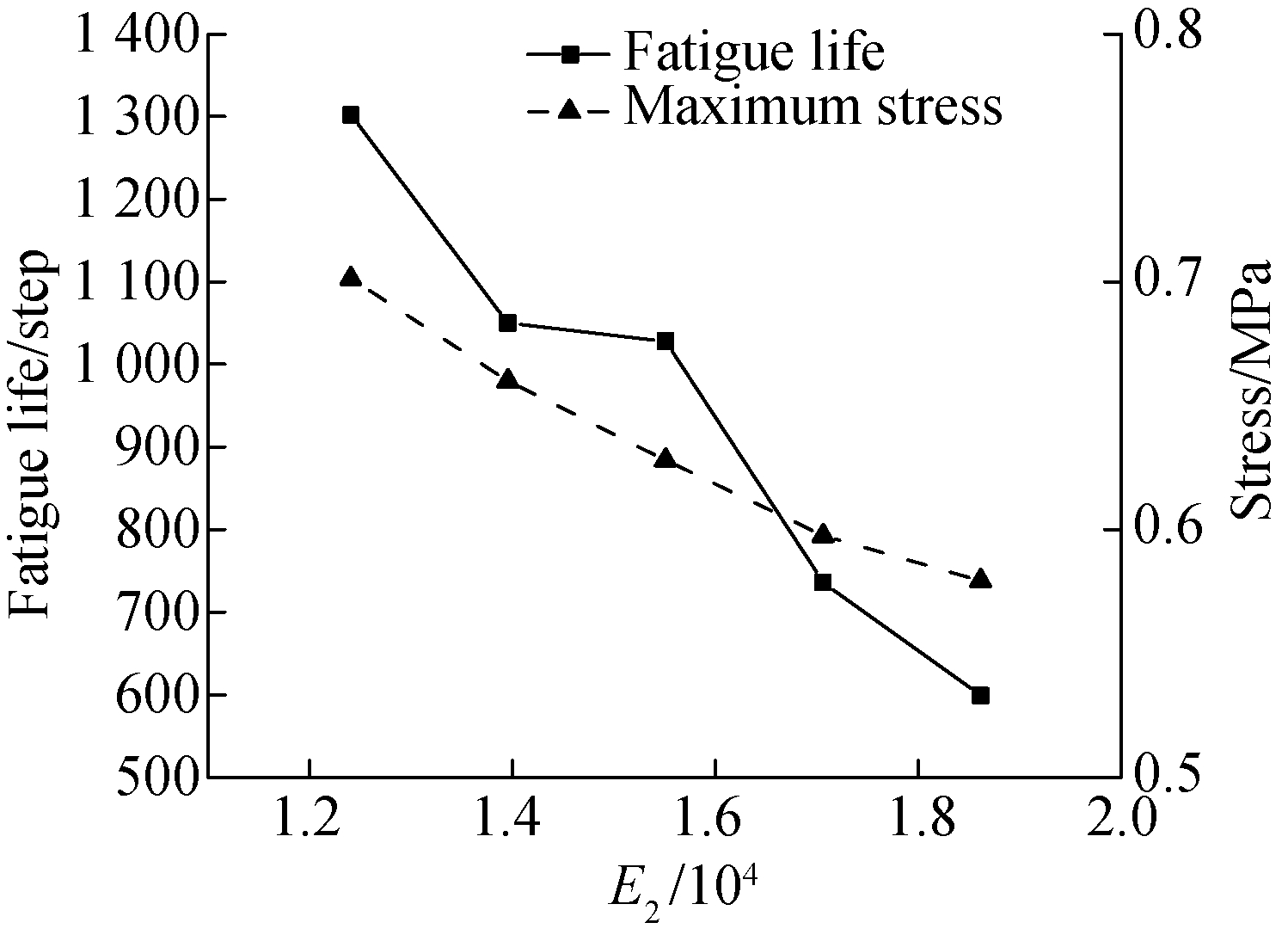
(b)Fig.8 Variations of fatigue life and stiffness.(a) VariableE1;(b) VariableE2
Only whenη1andη2vary simultaneously, the fatigue life changes but follows no pattern (see Fig.9). What is interesting in Fig.9 is whenη1increases, regardless ofthe increase or decrease ofη2, the fatigue life climbs, and vice versa. Compared toE1andE2,η1andη2impact less on fatigue life and only cause an obvious variation after enlarging 100 times. As the initial stiffness varies from 3 951 to 3 959 MPa, the effects on the initial stiffness and maximum stress can be both ignored. Thus, althoughη1andη2do not influence the stiffness of the material, they affect the fatigue life to a limit.
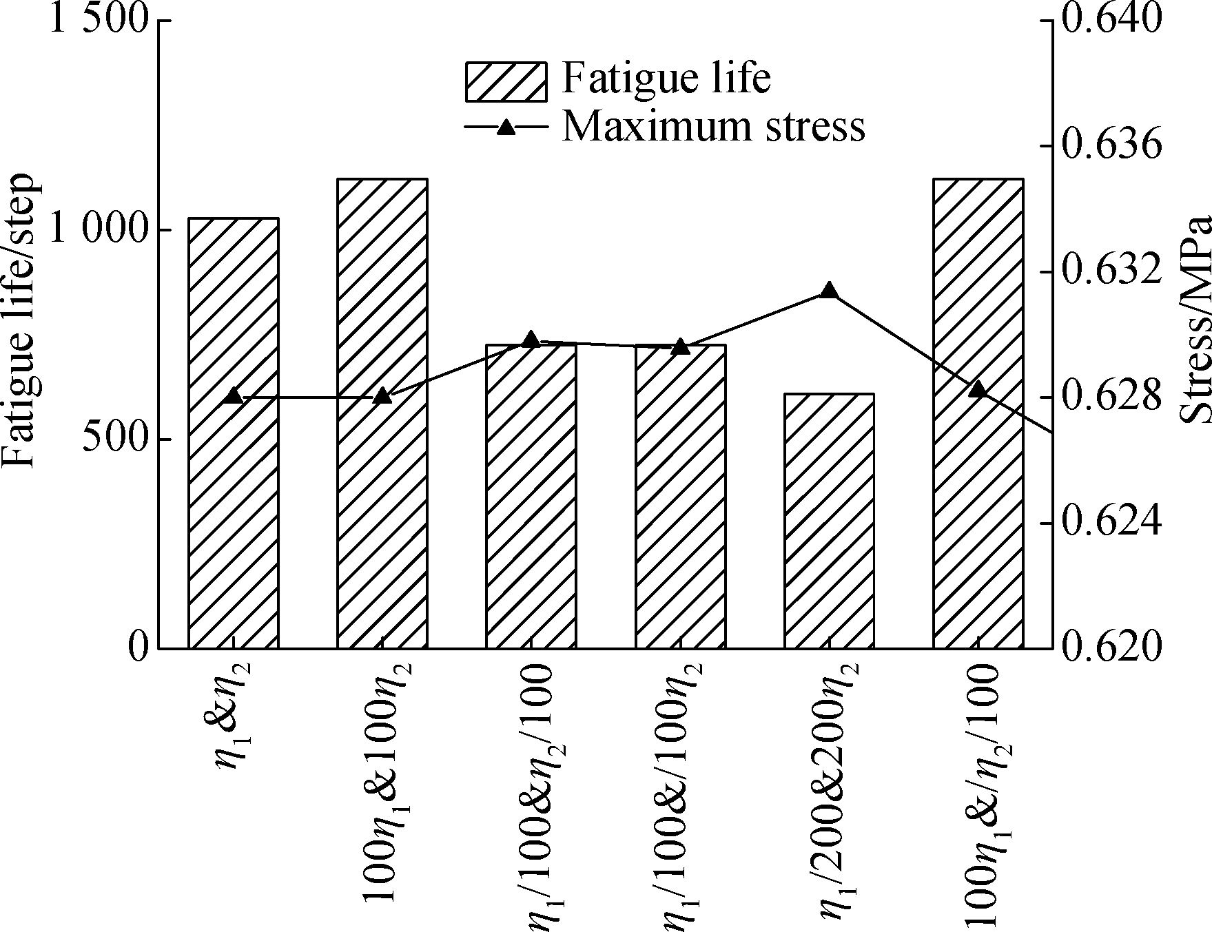
Fig.9 Variations of fatigue life and stiffness vs. viscosity
2.4 Evaluation of high modulus asphalt
From above, when the asphalt modulus increases and the penetration grade decreases,E1tends to increase, whileE2tends to decrease, andη1andη2vary diversely, which is in accordance with the previous study[21].To simulate the characteristics of high modulus asphalt, four parameters were changed simultaneously. The virtual experimental results above show that the effects ofη1andη2on fatigue life are negligible compared withE1andE2under equivalent amplification. Thus, different scaling factors were applied to the parameters.
Next, a new situation is taken into consideration:η1is expanded to 100 times, withE1to 1.15 times andE2to 0.95 times. Fatigue life increased from 1 208 to 2 628, while initial stiffness and maximum stress increased from 3 959 and 628 to 4 049 and 648, respectively. It is clear that the life of a high modulus asphalt mixture specimen is prolonged.
According to Lee et al.[22], adopting high modulus asphalt to improve fatigue life was demonstrated through field tests. The results in this paper verified the conclusion based on the discrete element method, and explained the performance of high modulus asphalt mixture in the rheological level of Burger’s parameters thatη1,E1andE2are related to the variation of fatigue life.
1) In this paper, a virtual three-dimensional trapezoidal specimen of asphalt mixture was established in PFC. Based on the virtual model, two-point trapezoidal bending fatigue test was conducted on the specimen. The model was verified with the comparison between simulating and laboratory test results. Then, the fatigue performance of the specimen was evaluated with verified top controlled displacement and Burger’s model parameters.
2) In a single virtual fatigue test, the force applied on the top of the specimen reduced rapidly and then slowed down to a balanced value eventually. Stiffness and maximum stress decreased simultaneously.
3) With the increase of the applied displacement, the fatigue life of the specimen declined. And, the fatigue life of the virtual specimen increased when the Burger’s model parametersE1were enhanced andE2reduced.The parametersη1andη2have less impact on the fatigue life of the specimen. The stiffness of the material mainly contributes to the increase ofE1and the decrease ofE2. Thus, HMAC with higher stiffness has longer fatigue life.
4) In general, high modulus asphalt with lower penetration grade is recommended in this paper to improve the fatigue life of asphalt mixture, and this can be applied to extend the life of the asphalt pavement in road engineering.
[1]Diefenderfer B K, Maupin G W Jr. Field trials of high-modulus high-binder-content base layer hot-mix asphalt mixtures[J/OL].Biotechniques, 2010,27(3). https://trid.trb.org/view.aspx?id=986723.
[2]Denneman E, Petho L, Verhaeghe B, et al. High modulus asphalt (EME) technology transfer to South Africa and Australia: Shared experiences[C/OL]//ConferenceonAsphaltPavementsforSouthernAfrica. Pilanesberg, South Africa, 2015. http://researchspace.csir.co.za/dspace/bitstream/handle/10204/8248/Verhaeghe_2015.pdf?sequence=1&isAllowed=y.
[3]Geng H, Clopotel C S, Bahia H U. Effects of high modulus asphalt binders on performance of typical asphalt pavement structures[J].ConstructionandBuildingMaterials, 2013,44: 207-213. DOI:10.1016/j.conbuildmat.2013.03.035.
[4]Corté J F. Development and uses of hard-grade asphalt and of high-modulus asphalt mixes in France[J].TransportationResearchCircular, 2001,503: 12-31.
[5]Hern ndez M I G. High modulus asphalt concrete: A long life asphalt pavement[J/OL].JournalofCivil&EnvironmentalEngineering, 2015. http:// dx.doi.org/10.4172/2165-784X.1000188.DOI:10.4172/2165-784x.1000188.
[6]Airey G D, Choi Y K, Collop A C, et al. Combined laboratory ageing/moisture sensitivity assessment of high modulus base asphalt mixtures (with discussion)[C]//2005JournaloftheAssociationofAsphaltPavingTechnologists:FromtheProceedingsoftheTechnicalSessions. Long Beach, CA, USA, 2005,74:307-345.
[7]Ma T, Wang H, Huang X M, et al. Laboratory performance characteristics of high modulus asphalt mixture with high-content RAP[J].ConstructionandBuildingMaterials, 2015,101: 975-982. DOI:10.1016/j.conbuildmat.2015.10.160.
[8]Benta A, Duarte C, Almeida-Costa A, et al. Design and performance of a warm high-modulus asphalt concrete[J].JournalofCleanerProduction, 2015,95: 55-65. DOI:10.1016/j.jclepro.2015.02.057.
[9]Zhang X N, Yang P. Finite element analysis of high modulus asphalt pavement[J].InternationalJournalofAdvancementsinComputingTechnology, 2012,4(2): 72-79.
[10]Zheng M L, Han L L, Qiu Z P, et al. Simulation of permanent deformation in high-modulus asphalt pavement using the Bailey-Norton creep law[J].JournalofMaterialsinCivilEngineering, 2016,28(7):04016020. DOI:10.1061/(asce)mt.1943-5533.0001511.
[11]Ullidtz P. Distinct element method for study of failure in cohesive particulate media[J].TransportationResearchRecord:JournaloftheTransportationResearchBoard, 2001,1757:127-133. DOI:10.3141/1757-15.
[12]Buttlar W, You Z. Discrete element modeling of asphalt concrete: Microfabric approach[J].TransportationResearchRecord:JournaloftheTransportationResearchBoard, 2001,1757:111-118. DOI:10.3141/1757-13.
[13]Liu Y, Dai Q L, You Z P. Viscoelastic model for discrete element simulation of asphalt mixtures[J].JournalofEngineeringMechanics, 2009,135(4):324-333. DOI:10.1061/(asce)0733-9399(2009)135:4(324).
[14]Chen J, Huang X M. Simulation of fracture process of asphalt mixture using three-dimension discrete element method[J].JournalofSouthChinaUniversityofTechnology(NaturalScienceEdition), 2012,40(7): 21-26.(in Chinese)
[15]British Standards Institution. BS EN 12697-24 Bituminous mixtures—test methods for hot mix asphalt—Part 24:Resistance to fatigue[S]. London: European Committee for Standardization, 2004.
[16]Bodin D, de La Roche C, Chabot A. Prediction of bituminous mixes fatigue behavior during laboratory fatigue tests[C]//Proceedingsofthe3rdEurasphaltandEurobitumeCongress. Vienna, Austria, 2004: 1935-1945.
[17]Cheng J, Zhang D, Huang X M.Applicationofdiscreteelementparticleflowsoftwareinroadengineering[M]. Beijing:China Communications Press, 2015: 110-114. (in Chinese)
[18]Komba J J,Maina J W, Anochie-Boateng J K, et al. Analytical modelling of visco-elastic behaviour of hot-mix asphalt[C/OL]//SouthernAfricanTransportationConference. Pretoria, South Africa, 2012. https://researchspace.csir.co.za/dspace/bitstream/handle/10204/6037/Komba_2012.pdf?sequence=1&isAllowed=y.
[19]Cocurullo A, Airey G D, Collop A C, et al. Indirect tensile versus two-point bending fatigue testing[J].ProceedingsoftheInstitutionofCivilEngineers—Transport, 2008,161(4): 207-220. DOI:10.1680/tran.2008.161.4.207.
[20]He X Y, Yan J H. The application of high modulus asphalt technology[J].TranspoWorld,2009(7): 182-189. (in Chinese)
[21]Wu J W,Bai Y F,Collop A C, et al. Numerical simulation of uniaxial compression test for asphalt mortar with discrete element method[J].Highway,2012(3): 193-197. (in Chinese)
[22]Lee H J, Lee J H, Park H M. Performance evaluation of high modulus asphalt mixtures for long life asphalt pavements[J].ConstructionandBuildingMaterials, 2007,21(5): 1079-1087.DOI:10.1016/j.conbuildmat.2006.01.003.
References
摘要:为了研究法国高模量沥青混凝土疲劳性能及Burger’s模型参数与疲劳寿命之间的关系,在离散元软件PFC3D中建立了沥青混凝土锥棱柱两点疲劳弯曲试验的虚拟模型.计算了虚拟试件的初始刚度及达到疲劳时的最大接触应力,并与实测单次疲劳试验曲线对比,验证了用DEM模拟疲劳试验的可行性.然后研究端部位移及Burger’s模型中各项参数(E1,E2,η1,η2)对疲劳寿命的影响.数值模拟结果表明,随着端部控制位移增大,到达疲劳时最大应力增大.研究证实:随着沥青砂浆Burger’s 模型参数中E1增大,E2减小,沥青模量增大,沥青混合料的疲劳寿命得到有效提升;η1和η2对疲劳寿命的影响较小.
关键词:高模量沥青混凝土;数值模拟;Burger’s参数;疲劳寿命
中图分类号:U416.2
![]()
JournalofSoutheastUniversity(EnglishEdition) Vol.33,No.3,pp.293⁃300Sept.2017 ISSN1003—7985
DOI:10.3969/j.issn.1003-7985.2017.03.006
Foundationitem:The National Natural Science Foundation of China(No. 51378121).
Citation:Cao Qingqing, Liu Xiuyu, Wang Hao, et al. Simulation and analysis of two-point bending fatigue test of asphalt concrete based on discrete element model[J].Journal of Southeast University (English Edition),2017,33(3):286-292.
DOI:10.3969/j.issn.1003-7985.2017.03.006.