Abstract:To study the effect of the contact angle and helix angle on slide-roll ratio at the ball contact points under the accelerated motion state of ball screw mechanism (BSM), the curve theory in differential geometry and the homogeneous transformation matrix are used to establish the acceleration kinematics model of BSM. The model can be used to describe the accelerated motion relationships among the screw, balls and nut, calculate the acceleration of relative motion at the contact points between the balls and raceways, and analyze five accelerated motion rules between the balls and raceways. It also conducts a simulation analysis of the slide-roll ratio relationship between the accelerations at the ball center and the contact point of ball under different contact angles and helix angles. As shown by the analysis, with the increase in the BSM’s contact angle, the slide-roll ratio at the contact points decreases, and the contact angle has a relatively significant effect on the slide-roll ratio. However, with the decrease in the BSM’s helix angle, the slide-roll ratio at the contact points decreases, and the helix angle has a relatively insignificant effect on the slide-roll ratio. By measuring the accelerations of both the screw and nut under the accelerated motion state, it also verifies the existence of the slide-roll mixed motion at the ball contact point A between the ball and the screw raceway and pure rolling at the ball contact point B between the ball and the nut raceway during the accelerated motion.
Key words:ball screw mechanism; contact angle; helix angle; slide-roll ratio
Ball screw mechanism (BSM) has a very complex motion structure, and the motion rules of ball are particularly complex. The ball has a combined motion consisting of its rotation around the screw and a self-spin, and its motion rules directly affect the wear and precision retaining ability of the BSM. Wei et al.[1-3]introduced the curve theory in differential geometry to analyze the motion rules of the ball considering the effect of the elastic deformation of the contact angle and found that the self-spin and rotational angular velocities of the ball have an approximately linear relationship with the rotational velocity of the screw. Lin et al.[4-5]confirmed the existence of both the rolling and sliding motions relative to each other between the ball and raceways during the operation of BSM and proposed a calculation model to estimate the transmission efficiency. Li et al.[6] used nominal diameter, ball diameter, helix angle, and other structural parameters as the variables to establish the dynamic contact angle model of BSM and investigated the effects of structural parameters on the contact angle under different working conditions. Chen et al.[7] analyzed the change in the BSM’s contact angle under a high velocity and used the contact angle as the variable to reflect the effect of the ball’s position relationship on the axial rigidity. Gnanamoorthy and Govindarajan et al.[8-9]identified the slide-roll ratio of the contact points as the key factor influencing the wear speed of the contact area. Ma et al.[10] affirmed the influencing rules of the contact angle and helix angle of the BSM on the slide-roll ratio and found that both the contact angle and helix angle had an opposite trend of the slide-roll ratio, and the increase in the helix angle can significantly decrease the slide-roll ratio of the nut contact point. Hu et al.[11] found five different motion states among the ball, screw raceway and nut raceway by analysis and also evaluated the effects of the motion velocity of the ball on the slide-roll ratio. In the above cases, the motion rules of the ball were explored when the BSM is under a uniform velocity and quasistatic state, and the ball is in a steady motion and under an equilibrium condition of forces[12-14]. However, during the acceleration of the BSM, the ball contact points are under a disequilibrium condition of forces, and the contact points are not fully lubricated, aggravating the wear of the BSM. The motion characteristics of the ball during the acceleration of the BSM decreased the wear of the BSM during this process and increased its precision and service life.
In this study, the curve theory in differential geometry and the homogeneous transformation matrix are used to establish the acceleration kinematics model of the BSM, and then this model is used to deduce the accelerated motion rules among the screw, balls, and the nut and calculate five accelerated motion characteristics possibly among the screw raceway, the ball and the nut raceway. It also analyzes the effects of the contact angle and helix angle on the acceleration of the ball and slide-roll ratio of the contact points. It is found that the increase in the contact angle can decrease the slide-roll ratio of the contact points; in contrast, the decrease in the helix angle can decrease the slide-roll ratio of the contact points. Finally, it also verifies the existence of the slide-roll mixed motion at the ball contact point A and pure rolling at the ball contact point B during the accelerated motion of the screw.
1.1.1 Position of the ball contact point
In order to facilitate the systematic study of the kinematic rules of the ball, two Cartesian coordinate systems (XA,YA,ZA) and (XB,YB,ZB) on the ball contact points must be established based on the inertial coordinate system OWXWYWZW and the Frenet-Serret coordinates OHtnb. As shown in Fig.1, contact points including contact point A between the ball and screw and contact point B between the ball and nut, and the contact points A and B regard the coordinate origins as contact points just coming into contact. The XA and XB axes are parallel to the tangential direction of the ball raceway helix path t, and the ZA and ZB axes are perpendicular, respectively, to the tangent plane of the screw raceway and the nut raceway, and YA and YB axes are calculated by the right-hand rule in the Cartesian coordinate system.
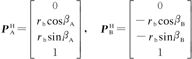
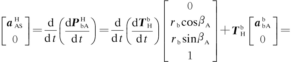
The contact angle of the BSM determines not only the relative position relationship between the balls and raceways, but also the motion relationships among the screw, balls, and the nut. The position vectors of contact point A between the ball and the screw raceway and contact point B between the ball and the nut raceway (see Fig.2) in the Frenet-Serret coordinate system OHtnb are as follows:
(1)
where βA is the contact angle between the ball and the screw raceway;βB is the contact angle between the ball and the nut raceway; and rb is the radius of the ball.
Taking the right-hand screw as an example for the convenience of studying the BSM, the nut moves along the negative direction of the ZW axis when the screw rotates around the positive direction of the ZW axis, and the contact angles βA and βB are positive. CS is the arc center of the normal section of the screw’s raceway, and CN is the arc center of the normal section of the nut’s raceway.

Fig.1 Three coordinate system
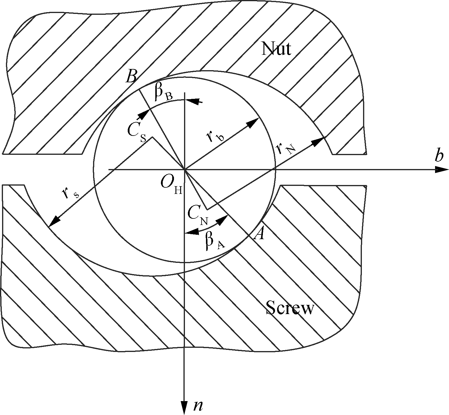
Fig.2 Contact angle
1.1.2 Analysis of the acceleration of BSM
The angular acceleration of the BSM during the motion can be expressed as ![]() =
=![]() . Based on Refs.[11,15], the position vector of point A on the screw in the OWXWYWZW coordinate system can be expressed as
. Based on Refs.[11,15], the position vector of point A on the screw in the OWXWYWZW coordinate system can be expressed as

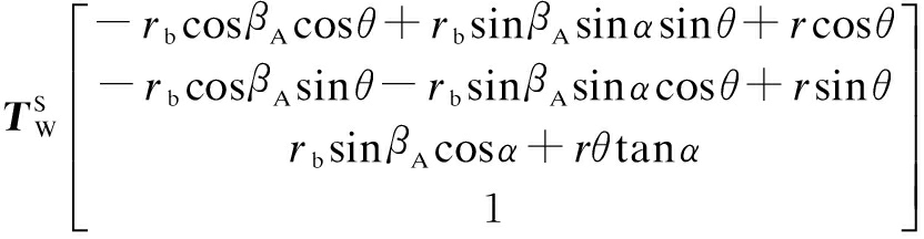
(2)
Similarly, the position vector of point B on the screw in the OWXWYWZW coordinate system can be expressed as

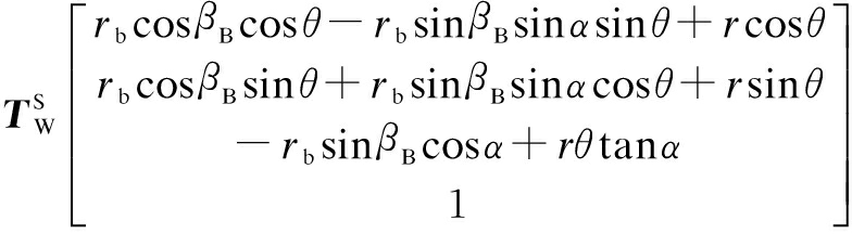
(3)
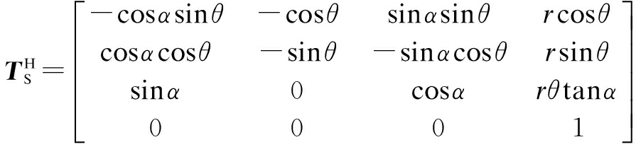
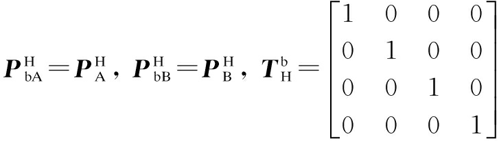
where PW=![]() PS, PS=
PS, PS=![]() PH; r is the screw pitch radius, namely the radius of the helix path; and α is the helix angle of the ball screw mechanism.
PH; r is the screw pitch radius, namely the radius of the helix path; and α is the helix angle of the ball screw mechanism.

and
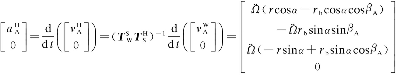
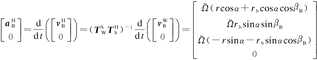
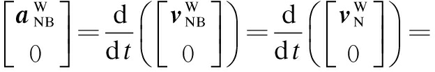
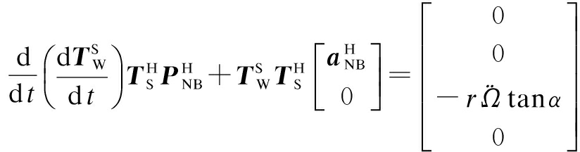
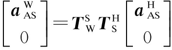
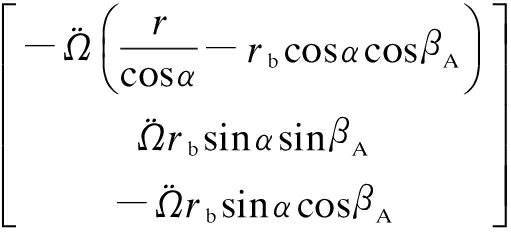
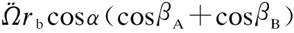
By solving the second-order derivative of time using Eqs.(2) and (3), the acceleration matrices of points A and B on the screw in the coordinate system OWXWYWZW and the Frenet-Serret coordinate system OHtnb, respectively, can be calculated as follows:

(4a)

(4b)
(4c)
(4d)
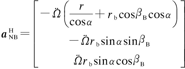
Assuming that the motion acceleration of the ball center relative to the screw in the tangential direction of the helix path is ![]() and its angular acceleration relative to the coordinate system OHtnb is α=[
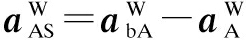
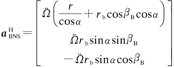
and its angular acceleration relative to the coordinate system OHtnb is α=[![]() ]T, the motion accelerations (i.e., relative sliding accelerations) of contact points A and B on the ball relative to points A and B on the screw, respectively, in the coordinate system OHtnb can be expressed as
]T, the motion accelerations (i.e., relative sliding accelerations) of contact points A and B on the ball relative to points A and B on the screw, respectively, in the coordinate system OHtnb can be expressed as

(5a)

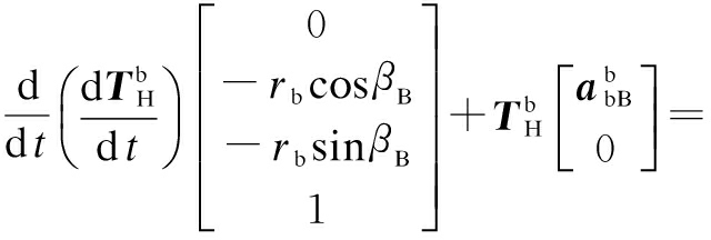
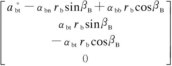
(5b)
where

Using Eq.(3), the position vector of point B on the nut in the coordinate system OWXWYWZW can be calculated as follows:

(6)
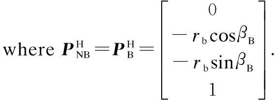
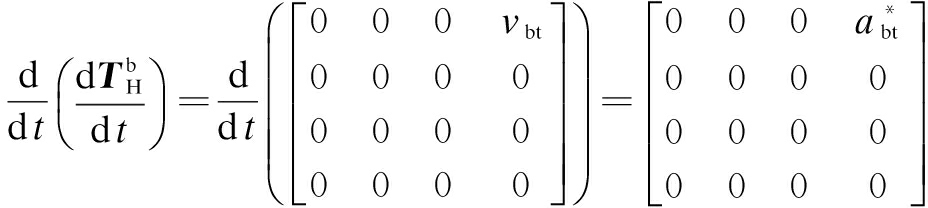
By solving the first-order derivative of time using Eq.(6), the velocity vector of point B on the nut in the coordinate system OWXWYWZW can be calculated. By solving the second-order derivative using Eq.(6), the acceleration of point B on the nut in the coordinate system OWXWYWZW can be solved as follows:

(7)

(8)
During the accelerated motion of BSM, there is a relative motion between the common tangential plane of the nut’s raceway and the ball at the ball contact point B, and the relative acceleration of the nut relative to the coordinate system OHtnb in the OHB direction is zero, so we assume that the motion acceleration of point B on the nut relative to the coordinate system OHtnb is
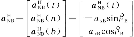
(9)
The acceleration of point B on the nut is shown in Eq.(8) then follows the acceleration of the nut, and the acceleration of the nut during the acceleration becomes ![]() =
= , which can be substituted into Eq.(8) to obtain
(10)
By substituting Eq.(10) into Eq.(9) for simplification, the acceleration of point B on the nut relative to point B on the screw can be obtained as
(11)
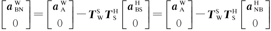
By combining Eq.(5b) and Eq.(11), the acceleration (i.e., relative sliding acceleration) of point B on the ball relative to point B on the nut can be obtained as follows:

(12)
1.2.1 Relative accelerated motion between the ball and screw raceway
Article 1 If the relative accelerated motion between the ball and screw raceway is pure rolling, i.e., if the relative sliding velocity at the contact point A between the ball and the screw raceway is zero, then

(13)
Using Eq.(13), we can obtain
(14)
By substituting Eq.(14) into Eq.(12), the relative sliding acceleration at point B between the ball and the nut raceway can be obtained as follows:
(15)
Using Eqs.(13) and (15), the calculated acceleration ![]() of the screw is not zero; therefore, it is impossible for the two contact points of the ball to simultaneously experience pure rolling.
of the screw is not zero; therefore, it is impossible for the two contact points of the ball to simultaneously experience pure rolling.
Article 2 If the relative accelerated motion between the ball and screw raceway is pure sliding, i.e., if there is no relative rolling at point A, the ball and nut are fixed together. Then, the BSM is similar to the trapezoidal lead screw, and the following equation holds.
(16)
At this point, the rotational angular acceleration of the ball relative to the screw is the rotational angular acceleration of the nut. Therefore, the angular acceleration of the ball can be expressed as
(17)
Using Eq.(17), because the acceleration of point A on the ball is equal to the acceleration of the nut (![]() =[
=[![]() ]T) when the nut and ball are fixed together, the relative sliding acceleration at point A can be expressed as follows:
]T) when the nut and ball are fixed together, the relative sliding acceleration at point A can be expressed as follows:
(18)
The relative sliding acceleration at point A can be calculated using Eqs.(18) and (5a) as follows:
(19)
Eq.(19) can be simplified as
![]() =
= =
=
(20)
Using Eq.(20), we can obtain

(21)
Substituting Eq.(21) into Eqs.(16) and (20), we have
αbnrb(sinβA+sinβB)-αbbrb(cosβA+cosβB)=
(22)
Article 3 If the ball and the screw raceway are relatively motionless, i.e., if the relative sliding acceleration at point A is zero and the motion acceleration and relative rotational acceleration of the ball center along the helix path of the screw are zero as well, Eq.(13) is established, and can be obtained using Eq.(14).

(23)
By substituting Eq.(23) into Eq.(12), the relative sliding acceleration at point B between the ball and the nut raceway can be obtained as
(24)
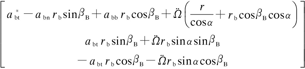
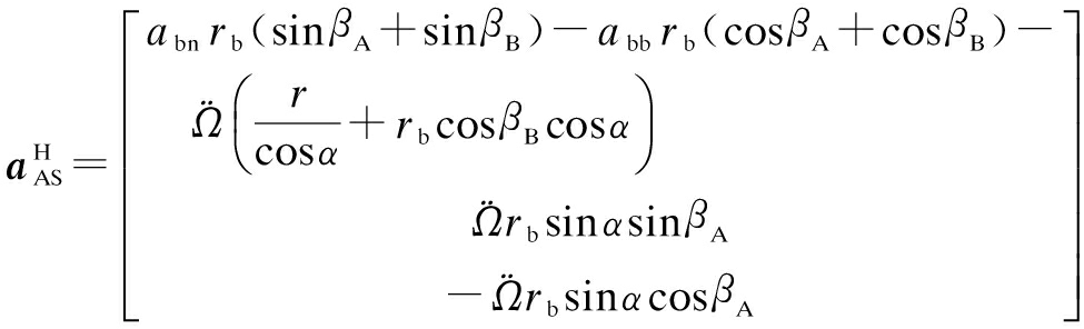
Article 4 If the motion between the ball and the screw raceway is the slide-roll mixed motion, the slide-roll ratio can be used to describe the motion of the contact point[8-9]. The acceleration of contact point A on the ball can be calculated using Eqs.(4) and (5) as follows:

(25)
Then, the slide-roll ratio of the ball at contact point A between the ball and the screw raceway in the tangential direction t of the helix path becomes
SA= ![]() =
=
![]()
(26)
Substituting Eqs.(4c), (5a) and (25) into Eq.(26), we obtain
SA=![]()
(27)
By substituting Eq.(23) into Eq.(27), the slide-roll ratio at point A, SA=0, can be obtained, i.e., there is a pure rolling or a motionless state.
By substituting Eq.(21) into Eq.(27), the slide-roll ratio at point A, SA=1, can be obtained, i.e., there is a full sliding state. This verifies the above three mentioned analysis results. Thus, the condition of the motion between the raceways of ball and screw being the rolling-sliding mixed motion is
0<SA<1
(28)
1.2.2 Relative accelerated motion between the ball and the nut raceway
Article 1 If the relative motion between the ball and the nut raceway is pure rolling, i.e., if the relative sliding acceleration of point B is zero, then

(29)
Using Eq.(29), we can obtain

(30)
By substituting Eq.(30) into Eq.(5a), the relative sliding acceleration of point A in the case of pure rolling at point B can be obtained as follows:
(31)
Similarly, according to Eqs.(29) and (31), the acceleration ![]() of the screw is not zero; therefore, it is impossible for the two contact points of the ball to simultaneously experience pure rolling.
of the screw is not zero; therefore, it is impossible for the two contact points of the ball to simultaneously experience pure rolling.
Article 2 If the relative motion between the ball and the nut raceway is pure sliding, i.e., if the balls and the screw are fixed together, then the BSM is similar to the trapezoidal lead screw.
Article 3 If the ball and the nut raceway are relatively motionless, i.e., if the ball and the nut are fixed together, then contact point A is under a pure sliding state.
Article 4 If the motion between the ball and the nut raceway is the slide-roll mixed motion, then the slide-roll ratio at contact point B between the ball and the nut raceway can be obtained by Eqs.(5b) and (11) as follows:
SB=![]() =
=![]() =
=

(32)
By substituting Eqs.(30) and (22) into Eq.(32), the slide-roll ratio at point B, SB=0, can be obtained; i.e., there is a pure rolling or motionless state.
By substituting Eqs.(23) and (24) into Eq.(32), the slide-roll ratio at point B, SB=1, can be obtained; i.e., there is a pure sliding state. This verifies the three abovementioned analysis results. Thus, the condition of the motion between the ball and the nut raceway being the rolling-sliding mixed motion is
0<SB<1
(33)
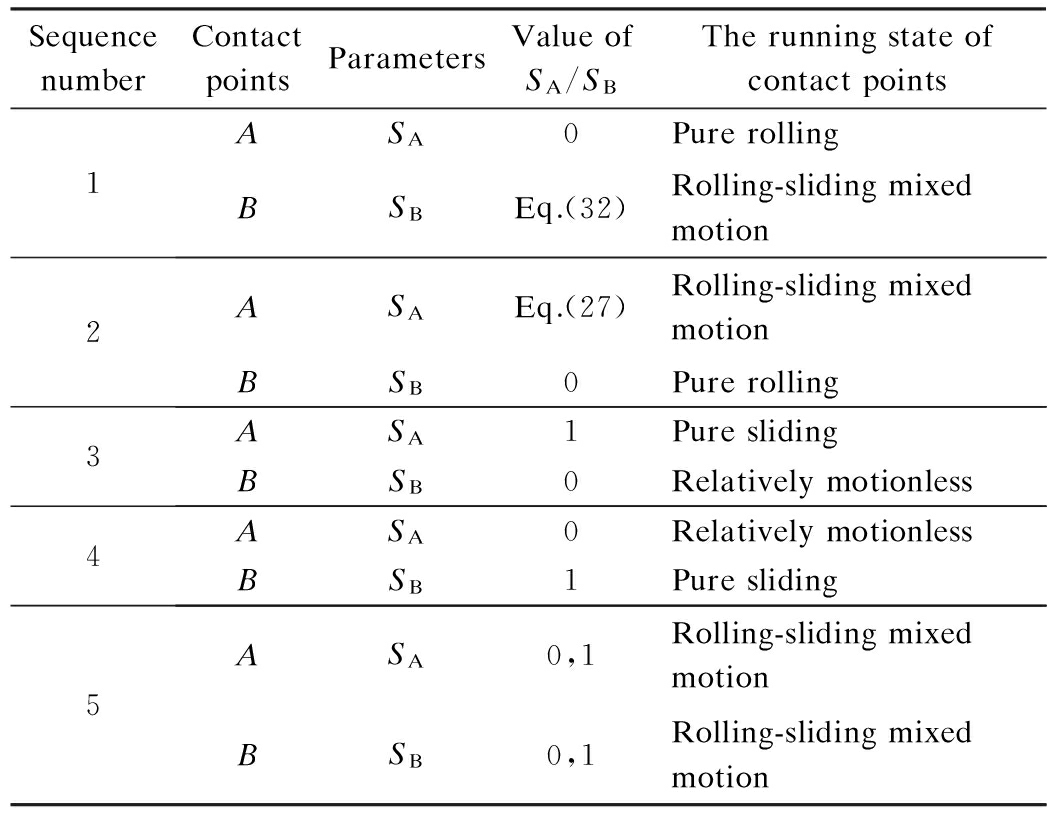
Based on the above mentioned analysis results, the relative motion forms of the contact points among the ball, the screw raceway, and the nut raceway are shown in Tab.1.
Tab.1 The slide-roll ratio of contact points
SequencenumberContactpointsParametersValueofSA/SBTherunningstateofcontactpoints1ASA0PurerollingBSBEq.(32)Rolling-slidingmixedmotion2ASAEq.(27)Rolling-slidingmixedmotionBSB0Purerolling3ASA1PureslidingBSB0Relativelymotionless4ASA0RelativelymotionlessBSB1Puresliding5ASA0,1Rolling-slidingmixedmotionBSB0,1Rolling-slidingmixedmotion
During the accelerated rotation of the screw shaft, the four extreme accelerated motion states of the ball are taken into consideration for the convenient analysis of the accelerated movement characteristics of the balls in the raceways.
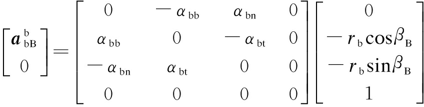
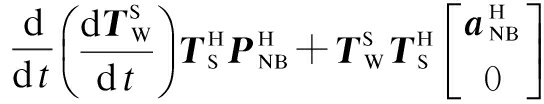
When there is pure rolling at contact point A between the ball and the screw raceway, and the rolling-sliding mixed motion at contact point B between the ball and the nut raceway, the acceleration of the ball can be calculated using Article 1 in Section 1.2.1, and then the acceleration of contact point B on the nut can be expressed as
(34)
By substituting Eq.(4a) and Eq.(11) into Eq.(34) for simplification, thus the acceleration in the nut is ![]() (ZW), and then
(ZW), and then ![]() (ZW) can be expressed as
(ZW) can be expressed as

(35)
(36)
When there is pure sliding at contact point A between the ball and the screw raceway and those of the ball and the nut are relatively motionless, the acceleration of the ball can be calculated using Article 2 in Section 1.2.1. The acceleration of contact point B on the nut is similar to Eq.(10), and the acceleration of the nut can be expressed as

(37)
When there is pure rolling at contact point B between the ball and the nut raceway, and the rolling-sliding mixed motion at contact point A between the ball and the screw raceway, the acceleration of the ball can be calculated using Article 1 in Section 1.2.2. By the same process as pure rolling at contact point A between the ball and the screw raceway, the acceleration of contact point B on the nut can be expressed as

(38)
According to Eq.(15) and Eq.(31), Eq.(38) can be transformed into
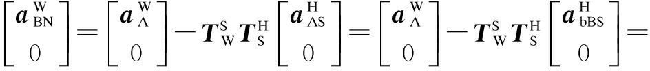

(39)
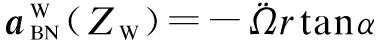
In order to facilitate the computing, supposing that βA=βB. Using Eq.(39), the acceleration of the nut can be calculated as ![]() (ZW)=-
(ZW)=-![]() rtanα.
rtanα.
When there is pure sliding at contact point B between the ball and the nut raceway, the ball and the screw raceway are relatively motionless and form an integrated whole. The acceleration of the ball can be calculated using Article 2 in Section 1.2.2. The acceleration of contact point B between the ball and the nut raceway is similar to pure sliding at contact point A between the ball and
the screw raceway, and the acceleration of the nut can be expressed as

(40)
In the BSM, the screw drives the ball while the ball drives the nut; therefore, the acceleration of the ball at contact point A in the tangential direction t is less than that of the screw. Based on the relative acceleration relationship expression Eq.(5b) of the contact point A between the ball and the screw raceway and the relative acceleration relationship expression Eq.(12) of the contact point B between the ball and the nut raceway, we have

(41)
Considering the two ultimate accelerated motion states of the ball, i.e., it is motionless relative to the nut (Eq.(21)) and the screw (Eq.(23)), the acceleration range of the ball along the helix path of the screw is
(42)
Similarly, the angular acceleration range of the ball in the tangential direction of the helix path can be obtained using Eq.(13) and Eq.(14) as follows:

(43)
Assuming that

(44)
where -1≤g≤0.
The slide-roll ratio of the ball contact points can be obtained as
SA=
(45)
SB=
(46)
Based on a comprehensive consideration of Eq.(37), g should also satisfy the following condition:
g≥![]()
(47)
By substituting the parameters of the BSM shown in Tab.2 into Eq.(45) and Eq.(46) to achieve the values satisfying Eq.(42), Eq.(47) and -1≤g≤0, the relationship between ![]() and abn is shown in Fig.2 as well as that between the slide-roll ratio and abt(abn) can be worked out as shown in Figs.3 to 5.
and abn is shown in Fig.2 as well as that between the slide-roll ratio and abt(abn) can be worked out as shown in Figs.3 to 5.
Tab.2 Parameters of the BSM

ParametersValueScrewpitchradiusr/mm16.375Ballradiusrb/mm2.9765Helixangleα/(°)2.767Initialcontactangleβ/(°)44.35PitchL/mm5Rotationalangularaccelerationofthescrew¨Ω/(rad·s-2)200

(a) (b)
Fig.3 Relationship between ![]() and abn. (a) Relationship between
and abn. (a) Relationship between ![]() and abn; (b) Local enlarged drawing of
and abn; (b) Local enlarged drawing of ![]() and abn
and abn
To verify the motion rule of the ball contact points of the BSM during the accelerated motion, a test bench is established to test BSM in Fig.6. The acceleration and velocity of the nut are recorded by the laser interferometer during the acceleration process of screw. The working principle of the laser interferometer is based on the light refraction, and the laser head is fixed to the ground by three-foot shelf brackets. The refracting mirror is fixed on the servo motor fixed seat, and the reflector is fixed onto the moving platform. The moving platform is driven to move by the nut.
On this basis, the abovementioned four motion states of the nut are simulated and compared with the measured accelerations of the nut, as shown in Fig.7, and the effect of the accelerated motion of the screw on the nut velocity is shown in Fig.8.
While the BSM is running at a constant acceleration, the greater the contact angles, the smaller the values of abn/![]() , as shown in Fig.3. Under constant acceleration, the greater the helix angles, the larger the values of abn/
, as shown in Fig.3. Under constant acceleration, the greater the helix angles, the larger the values of abn/![]() , but their values are affected by the helix angle to a less degree than the contact angles. At the same time, with the increase in
, but their values are affected by the helix angle to a less degree than the contact angles. At the same time, with the increase in ![]() , abn/
, abn/![]() is constant.
is constant.
While the BSM is running at constant ![]() , SA and SB decreasing with the increase in the contact angles can be observed in Fig.4. Under constant
, SA and SB decreasing with the increase in the contact angles can be observed in Fig.4. Under constant ![]() , the greater the helix angles, the smaller the values of SA first and the larger values of SA later; however, the increase range of SA is smaller than the decrease range. The greater the helix angles, the larger the values of SB.With the increase in the absolute value of
, the greater the helix angles, the smaller the values of SA first and the larger values of SA later; however, the increase range of SA is smaller than the decrease range. The greater the helix angles, the larger the values of SB.With the increase in the absolute value of ![]() , the range of SA becomes greater. In contrast, with the increase in the absolute value of
, the range of SA becomes greater. In contrast, with the increase in the absolute value of ![]() , the range of SB is very small.
, the range of SB is very small.
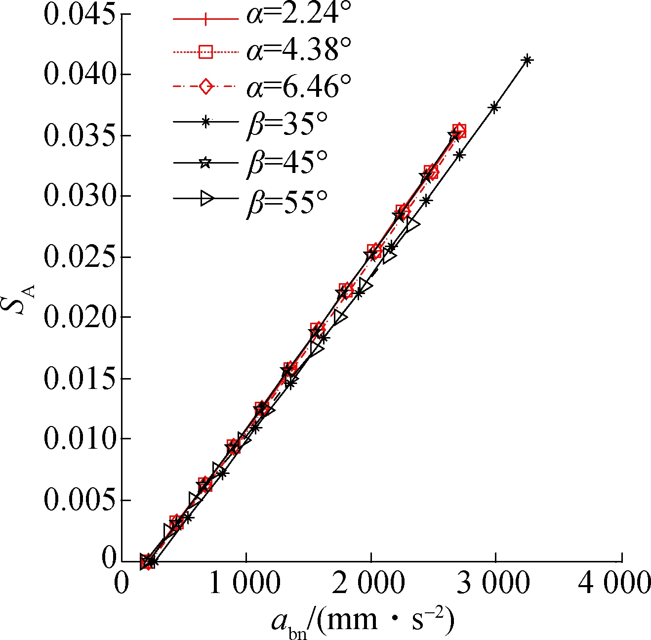
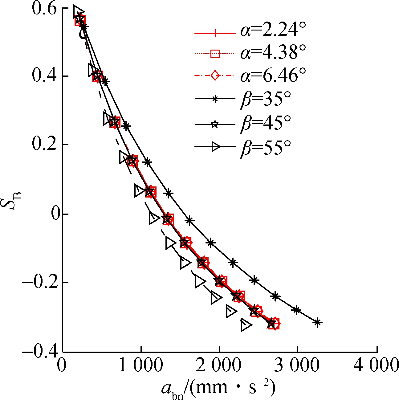
As shown in Fig.5, under constant abn, the greater the contact angles, the larger values of SA first and the smal-ler values of SA later, but the decrease range is greater. The greater the contact angles, the smaller the values of SB.The greater the helix angles, the smaller the values of SA, and the larger the values of SB. At the same time, with the increase in the value of abn, SA and SB show the same change trend under the influence of![]() .
.

(a) (b) (c)


(a) (b)

(c) (d)
Fig.5 Relationship between SA(SB) and αbn. (a) Relationship between αbn and SA; (b) Local enlarged drawing of αbn and SA; (c) Relationship between αbn and SB; (d) Local enlarged drawing of α

1—Reflector; 2—Moving platform; 3—BSM; 4—Refractor;5—Laser interferometer
Fig.6 Test bench of the BSM
The acceleration of the nut linearly increases with the increase in the acceleration of the screw, and the measured acceleration of the nut is consistent with the acceleration of the nut at ball contact point B when there is pure rolling (see Fig.7). Due to the existence of error in the processing of the BSM and the friction coefficient of the screw μA smaller than the friction coefficient of the nut μB, there is pure rolling at the ball contact point B between the ball and the nut raceway during the acceleration of the BSM. Whereas at ball contact point A, there is the slide-roll mixed motion.
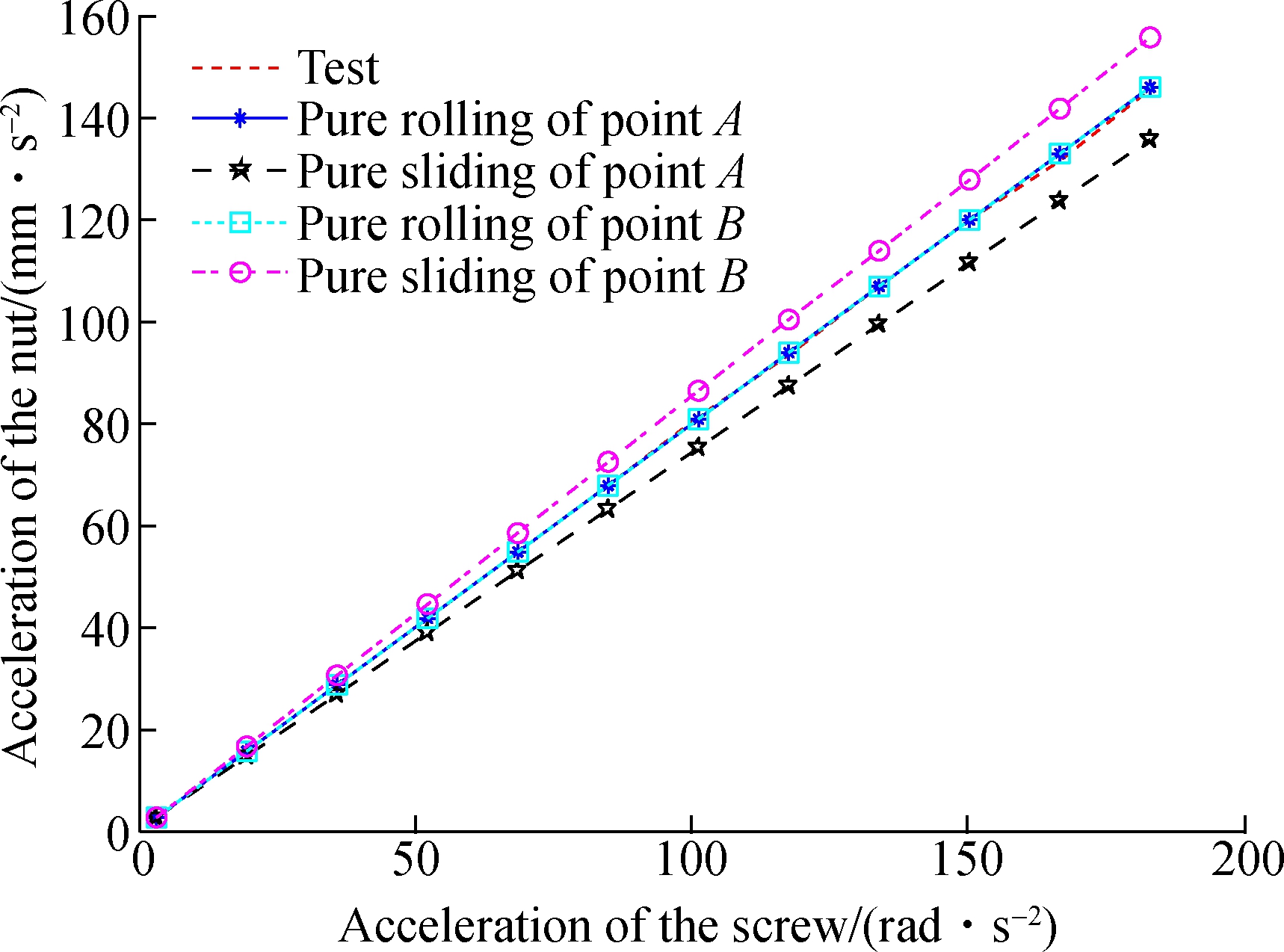
Fig.7 Acceleration relationship between the screw and nut
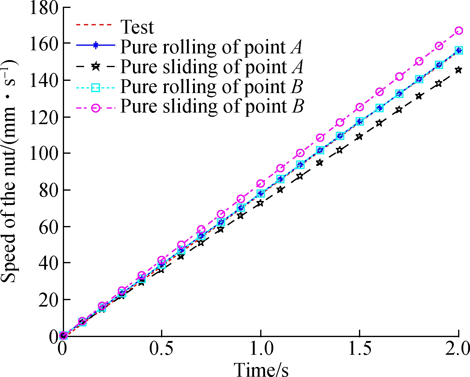
As shown in Fig.8, the measured initial velocity of the nut is lower than the velocity of the nut under the assumption that there is pure sliding at ball contact points A and B. However, with the increase in the velocity of the nut, the measured velocity exceeds the velocity of the nut when there is pure sliding at the ball contact point A. This is due to the slide-roll mixed motion at the ball contact point A, and with the increase of time, the velocity of the nut exceeds that of the pure sliding of contact point A.
(a)

(b)
Fig.8 The running velocity of the nut. (a) Running velocity of the nut; (b) Partial enlargement drawing of the running velocity of nut
By measuring the acceleration and velocity of the nut of the BSM, it is verified that there is a slide-roll mixed motion at the ball contact point A and the pure rolling at the ball contact point B during the acceleration of the BSM.
1) In this paper, the curve theory in differential geometry and the homogeneous transformation matrix is used to establish an acceleration kinematics model of the BSM.
2) By analyzing the relative accelerated motions between the ball and the raceways, it can be concluded that there may be five different accelerated motion states at the ball contact points A and B.
3) It also explores the effects of the contact angle and helix angle on ![]() and abn, SA and SB, as well as
and abn, SA and SB, as well as ![]() and abn during the accelerated motion of the screw. Increasing the contact angle can reduce the slide-roll ratio at contact point A of the ball, thus reducing the wear of the ball screw.
and abn during the accelerated motion of the screw. Increasing the contact angle can reduce the slide-roll ratio at contact point A of the ball, thus reducing the wear of the ball screw.
4) By measuring the acceleration and velocity values of the nut of the BSM, it is verified that there is a slide-roll mixed motion at ball contact point A and pure rolling at contact point B during the acceleration of the BSM. It can improve the service life of ball screws by reducing the friction coefficient at ball contact point A.
References
[1]Wei C C, Lin J F. Kinematic analysis of the ball screw mechanism considering variable contact angles and elastic deformations[J]. Journal of Mechanical Design, 2003,125(4):717-733. DOI:10.1115/1.1623761.
[2]Wei C C, Lin J F, Horng J H. Analysis of a ball screw with a preload and lubrication[J]. Tribology International, 2009,42(11):1816-1831. DOI:10.1016/j.triboint.2008.12.013.
[3]Wei C C, Lin J F, Horng J H. Kinematical analyses and transmission efficiency of a preloaded ball screw operating at high rotational speeds [J]. Mechanism and Machine Theory, 2011, 46(7): 880-898. DOI:10.1016/j.mechmachtheory.2011.02.009.
[4]Lin M C, Ravani B, Velinsky S A. Kinematics of the ball screw mechanism[J]. Journal of Mechanical Design,1994,116(3):849-855. DOI:10.1115/1.2919459.
[5]Lin M C, Velinsky S A, Ravani B. Design of the ball screw mechanism for optimal efficiency[J]. Journal of Mechanical Design,1994,116(3): 856-861. DOI:10.1115/1.2919460.
[6]Li M Q, Yu H, Li D Y, et al. Modeling for dynamic contact angle of ball screw mechanism aimed to structural parameters[J]. Transactions of the Chinese Society of Agricultural Engineering, 2016,32(4):98-104. (in Chinese)
[7]Chen Y J, Tang W C. Dynamic contact stiffness analysis of a double-nut ball screw based on a quasi-static method[J]. Mechanism and Machine Theory, 2014,73(2):76-90. DOI:10.1016/j.mechmachtheory.2013.10.008.
[8]Gnanamoorthy R, Govindaraian N, Mutoh Y. Effect of slide-roll ratio on the contact fatigue behavior of sintered and hardened steels[J]. Journal of Failure Analysis and Prevention, 2004,4(2):78-83. DOI:10.1361/15477020419082.
[9]Govindarajan N, Gnanamoorthy R. Rolling/sliding contact fatigue life prediction of sintered and hardened steels[J]. Wear, 2007, 262(1):70-78. DOI:10.1016/j.wear.2006.03.053.
[10]Ma S J, Liu G, Fu X, et al. Rolling-sliding characteristics of planetary roller screw considering elastic deformation[J]. Journal of Southeast University(Natural Science Edition), 2015,45(3):461-468. (in Chinese)
[11]Hu J Z, Wang M, Zan T. The kinematics of ball-screw mechanisms via the slide-roll ratio[J]. Mechanism and Machine Theory, 2014,79:158-172. DOI:10.1016/j.mechmachtheory.2014.04.017.
[12]Zhou C G, Feng H T, Chen Z T, et al. Correlation between preload and no-load drag torque of ball screws [J]. International Journal of Machine Tools and Manufacture, 2016, 102: 35-40. DOI:10.1016/j.ijmachtools.2015.11.010.
[13]Liu X, Mao X, Liu H, et al. Method for identifying feed-drive system dynamic properties using a motor current[J]. International Journal of Machine Tools and Manufacture, 2016, 110: 92-99. DOI:10.1016/j.ijmachtools.2016.08.007.
[14]Xu N N, Tang W C, Chen Y J, et al. Modeling analysis and experimental study for the friction of a ball screw[J]. Mechanism and Machine Theory, 2015,87:57-69.
[15]Hu J Z, Wang M, Gao X S, et al. Axial contact stiffness analysis of position preloaded ball screw mechanism[J]. Journal of Mechanical Engineering, 2014,50(7): 60-69.DOI:10.3901/jme.2014.07.060. (in Chinese)
摘要:为研究滚珠丝杠副在加速运动状态下,接触角和螺旋升角对滚珠接触点处滑滚比的影响,利用曲线微分几何理论和相似坐标转换矩阵建立滚珠丝杠副的加速运动学模型.通过该模型可以获得丝杠、滚珠和螺母加速运动特性,滚珠与滚道接触点处的相对运动加速度值和滚珠与滚道之间的5种加速运动规律.仿真分析不同接触角和螺旋升角情况下的滚珠圆心加速度值和滚珠接触点的滑滚比.分析发现,随着滚珠丝杆副接触角的增加,接触点的滑滚比降低,并且接触角对滑滚比影响较大;相反,随着螺旋升角的减小,接触点的滑滚比降低,但螺旋升角对滑滚比的影响较小.通过实测滚珠丝杠副加速运动状态下丝杠和螺母加速度值,验证滚珠丝杠副在加速运动状态下滚珠与丝杠滚道接触A点存在滑滚混合运动,滚珠与螺母滚道接触B点存在纯滚动.
关键词:滚珠丝杠副;接触角;螺旋升角;滑滚比
中图分类号:TP132
DOI:10.3969/j.issn.1003-7985.2017.04.003
Received 2017-05-25,
Revised 2017-09-21.
Biographies:Kong Deshun(1980—),male, doctor, engineer; Wang Min(corresponding author), male, doctor, professor, Wangm@bjut.edu.cn.
Foundation items:The National Natural Science Foundation of China (No.51575014, 51505012), the Natural Science Foundation of Beijing (No.KZ201410005010), China Postdoctoral Science Foundation (No.2016M591033), Beijing Postdoctoral Research Foundation(No.2015ZZ-13).
Citation:Kong Deshun, Wang Min, Gao Xiangsheng. Effect of contact angle and helix angle on slide-roll ratio under the accelerated motion state of ball screw mechanism[J].Journal of Southeast University (English Edition),2017,33(4):398-408.
DOI:10.3969/j.issn.1003-7985.2017.04.003.