Structural joints are widely used in mechanical systems and industrial applications due to their low cost, easy assemblage and repair.However, due to the discontinuity of materials, frictional contact, mechanical micro-slippage or slapping along the contact interface, structural joints have become the main sources of structural nonlinearity and uncertainties[1-3].In many industrial applications, numerical modeling and analysis need to take the structural joints or boundary conditions into consideration for precise representation of nonlinear elements.However, the nonlinear behaviour depends on the applied excitation levels.Under a low excitation condition, the dynamic response is linear, while under a high excitation level, the nonlinearity is excited.Therefore, a more reliable mathematical or finite element (FE)model becomes more important during the product design stage, which helps engineers to predict the dynamic response or working conditions.By a FE model, it is impossible to reflect the essence of contact behaviors and describe its nonlinear dynamic characteristics for joint interface[4].
In order to increase the accuracy of the numerical model, the nonlinear factor cannot be ignored.A more accurate model will minimize the difference between the numerical analysis data and experimental results, and the characterization and validation process will improve the quality of the product for prediction and assessment.The mathematical modeling and analysis can be used as another identification method to extract the dynamic parameters and it is required that the mathematical modeling needs to reproduce the reality of a physical structure by experimental results.Luan et al.[5]proposed a simplified nonlinear dynamic model with bi-linear springs to model the dynamic behavior of pipe structures with structural joints.Wang et al.[6] investigated the nonlinear dynamic behaviors of two elastic rods connected by a joint and considered the effects of the clearance size on the multi-value response characteristics.Cai[7] developed the force-state mapping in the frequency domain to identify the nonlinear joint parameters of the complex structure with an unknown joint model.Wei et al.[8] studied the effect of nonlinear force-displacement characteristics of the bolted joint using the Iwan model based on the modal shape transfer principle.Many studies have been carried out to investigate the dynamic behaviour of some nonlinear structures.
In this study, a nonlinearity detection and quantification method is developed for structural joints by the harmonic balance method (HBM), which utilizes a number of measured vibration transmissibilities of the joint system and identifies the state of the unknown joint model in advance.The measured vibration transmissibilities will be used for extraction of nonlinear parameters by the reliable joint model.For linear cases, the modal parameters are obtained by standard techniques in the dynamic design process.For a jointed system and the uncertain boundary, the obvious shift of natural frequency or damping will be observed due to nonlinear behavior, and the varied modal parameters can be considered to be dependent of response amplitude, excitation type and frequency, etc.The parameters of structural joints can be identified for different steady state response levels, which allow the obtaining of nonlinear spring and damping force from measured vibration data corresponding to different base excitation levels.According to the HBM, an effective numerical model can be used to describe the weak nonlinear systems with the desired accuracy, which proves to be capable of presenting nonlinearities for the joint interface.
1 Experimental Preparation
1.1 Experimental setup
To investigate the nonlinearity and the uncertain boundary condition, a specimen was manufactured and an experimental setup was constructed.The experimental specimen can be considered as a concentrated mass with a rectangle shape, which has been used as a balance weight in the laboratory before.The structural dimensions of the mass are given by a length of 300 mm, width of 50 mm and thickness of 5 mm.The specimen is resting on a cushion and connected to the base of a shaking table by structural joints for extraction and identification of nonlinearity.It is seen from Fig.1 that the experimental system contains the specimen, fixture, shaking table, vibration controller, power amplifier, data acquisition system, acceleration transducer, etc.Three accelerometers are placed at the top of the mass rigidly and uniformly apart from each other to capture the output response and monitor its vibrations, and one accelerometer is put on the shaking table for control of input base excitation, as shown in Fig.2.All the measured responses are in the vertical direction.Standard vibration tests will be conducted to investigate the nonlinearity induced by joints or other uncertainty boundaries.
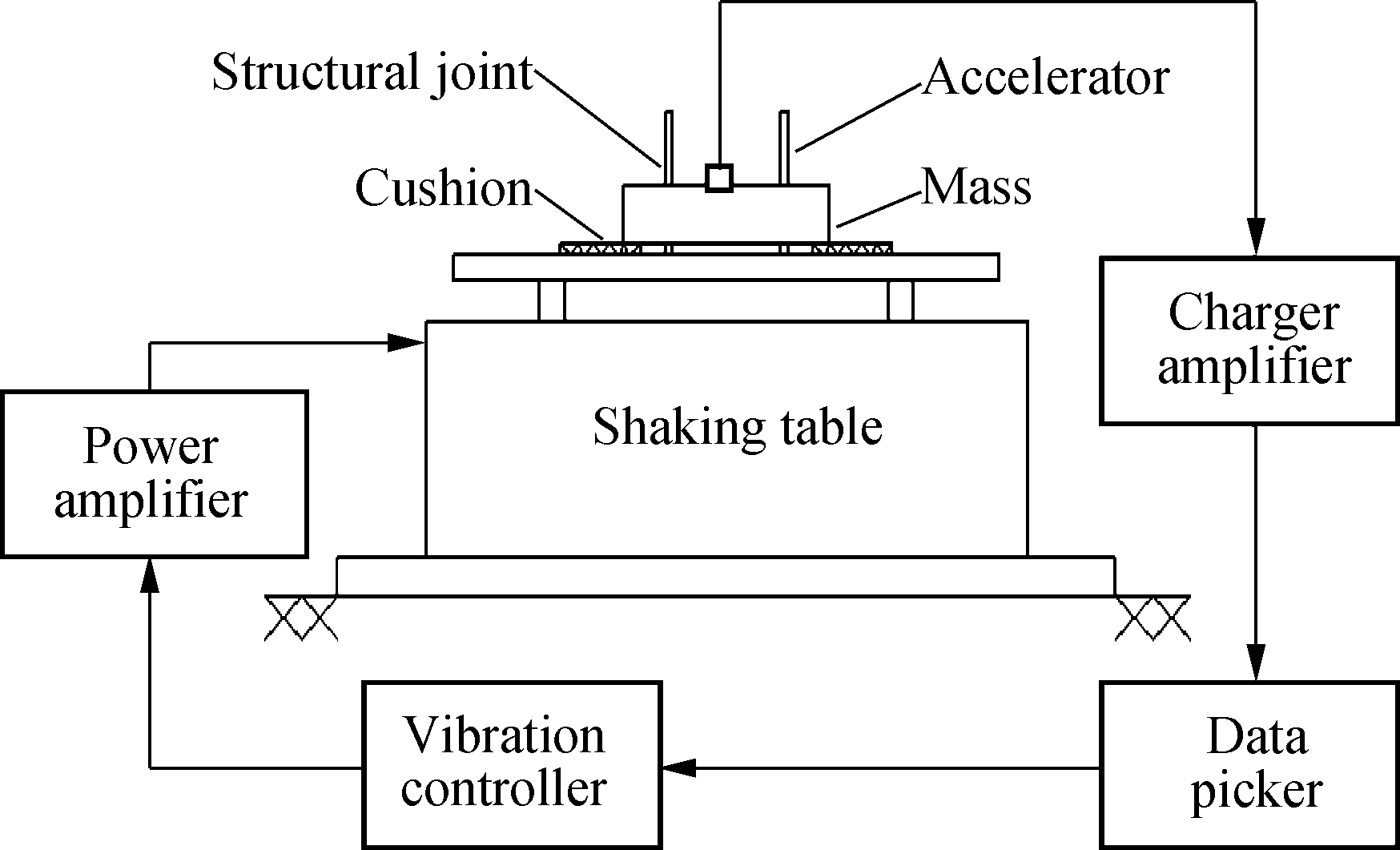
Fig.1 Schematic diagram of the experimental system
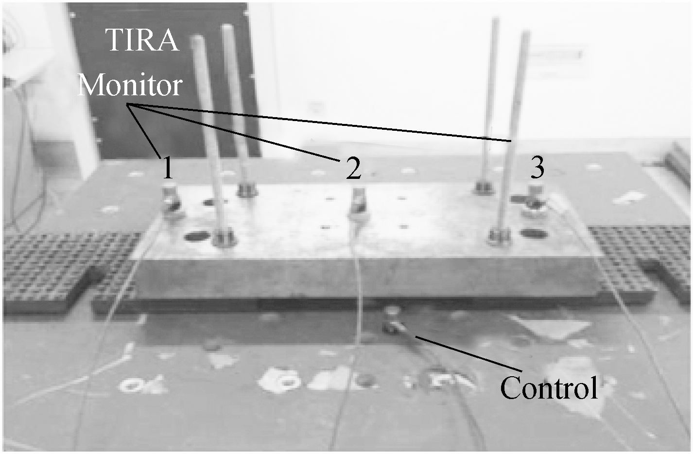
Fig.2 Three accelerometers placed on the mass and one on the base for control
1.2 Shaking table vibration test
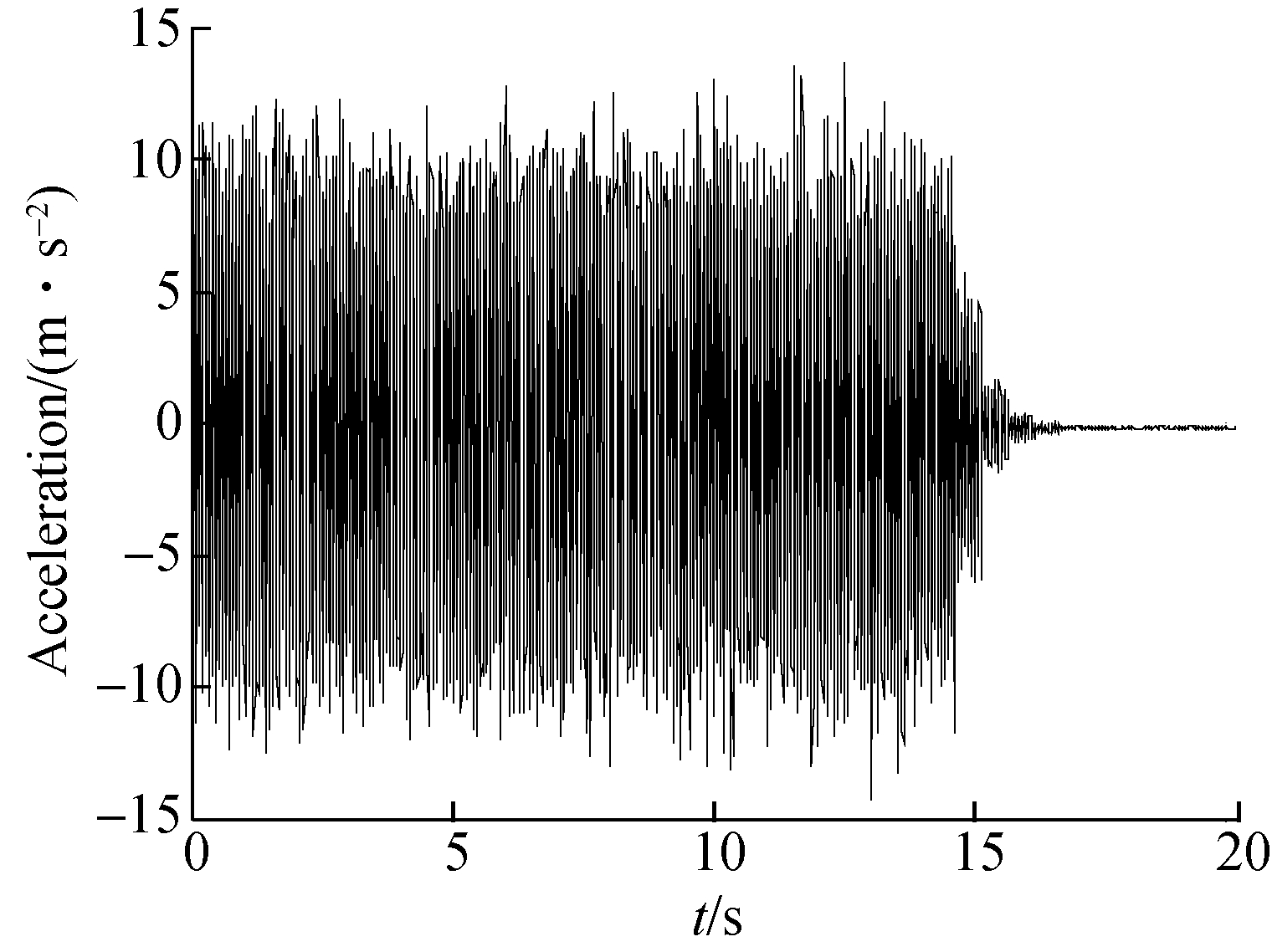
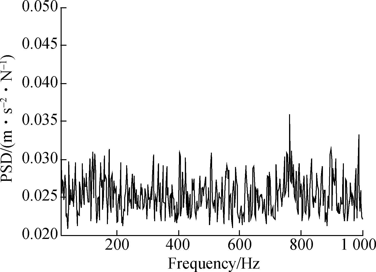
First, the specimen is excited by a random base excitation and the exterior excitation level is maintained at a low level by the controller, which aims to avoid its presumably assumed nonlinearity along the structural joint.Fig.3 shows the random base excitation measured on the base table.The time-domain data is plotted in Fig.3(a)and its spectrum range is plotted in Fig.3(b).The linear transmissibilities are the ratio between the mass response and base acceleration of three placed accelerometers, which are measured and shown in Fig.4.The results show that the dominated resonant resonance is around 181 Hz and the dominated mode is the mass rigid motion in the vertical direction judged by the coherence of three accelerometers’ output responses under random input base excitation.
(a)
(b)
Fig.3 Measured random input base excitation.(a)Time-history data; (b)Power spectral density
As three accelerometers have nearly the same outputs around the dominant resonance, the response of the middle point will be chosen for further investigation and nonlinear characterization.Another purpose of this study is to study some functional parameters of structural joints on their vibration property.To investigate the effect of pretension on output response, different pretension levels are applied to the structural joints conservatively, which aims to prevent material yield deformation and slipped screws.According to the exterior loading condition and its dynamic response, the nonlinear structure may be regarded as a linear structure if the internal nonlinear force is small enough that it can be ignored corresponding to small vibration amplitude.Fig.5 shows the transmissibilities for different pretension levels and Tab.1 gives the corresponding experimental resonant frequencies and damping ratios.The transmissibilites not only show the relationship between the excitation and response signals but also reveal some inherent structural properties.Similar results are obtained as in previous studies[9-10].Resonant frequency exhibits an obvious increase with the increase of the preload value and the damping property tends to be obvious if the bolted joints are adjusted to be loosened artificially, which reveals a stronger energy dissipation capacity and higher preload level.
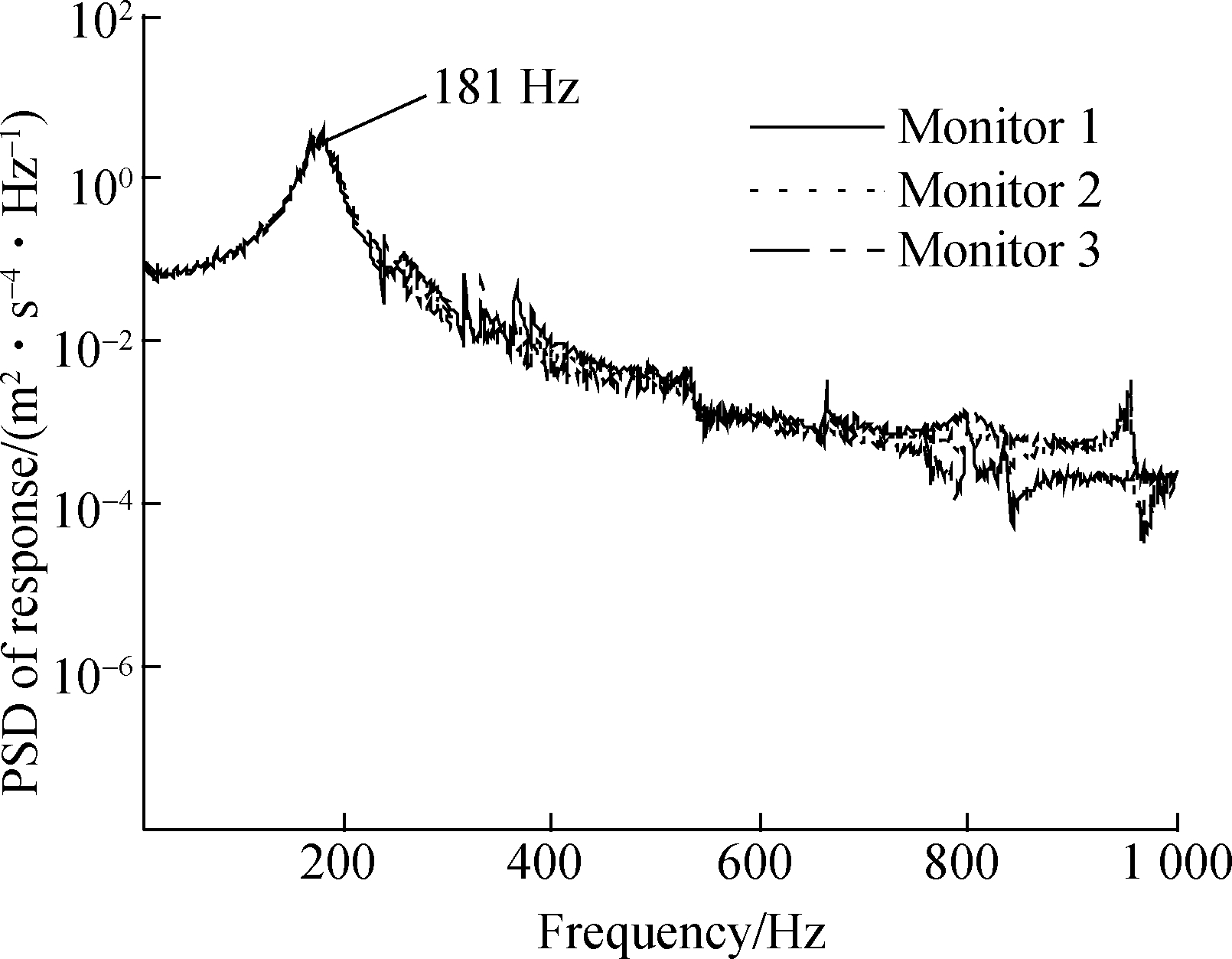
Fig.4 Three responses obtained from accelerometers on top of specimen under random input excitation
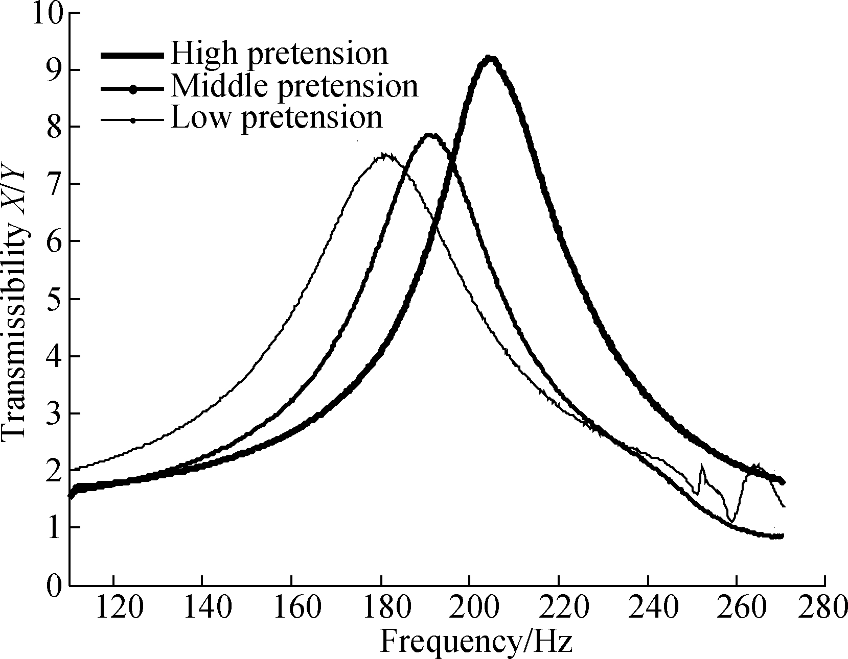
Fig.5 Linear vibration transmissibilities for different pretension levels
Tab.1 Resonant frequency and damping ratios
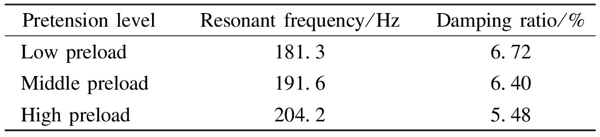
PretensionlevelResonantfrequency/HzDampingratio/%Lowpreload181 36 72Middlepreload191 66 40Highpreload204 25 48
In the second step, the jointed mass at the low pretension level is excited using a sweeping harmonic force which is chosen in a frequency band close to the first dominant resonant frequency from 150 to 200 Hz.In the case of a low preload condition, the effect of nonlinearity seems to be excited easily and it can also result in the increase of system nonlinearity as the preload level decreases[11].A higher preload level can increase tightness between two substructures that makes it difficult for relative motion across the connections and loosened structural joints will be chosen for nonlinearity measurement and identification subsequently.Different base excitation levels are maintained as a constant one for all excitation frequencies, as shown in Fig.6.By increasing the excitation level, it is possible to produce a variety of dynamic behaviours ranging from linear, weakly nonlinear up to even strongly nonlinear behavior due to the structural joints or another uncertainty.The steady state response of the structure and its corresponding base excitations are recorded and the nonlinear transmissibilities are obtained and shown in Fig.7, which confirms the presence of nonlinearity by the changes in resonant frequency and amplitude values.
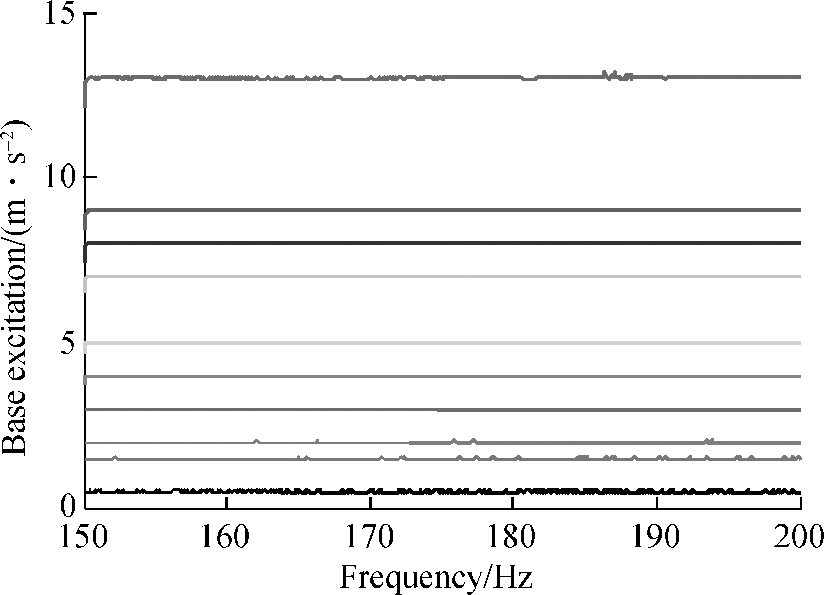
Fig.6 Constant base excitation acceleration
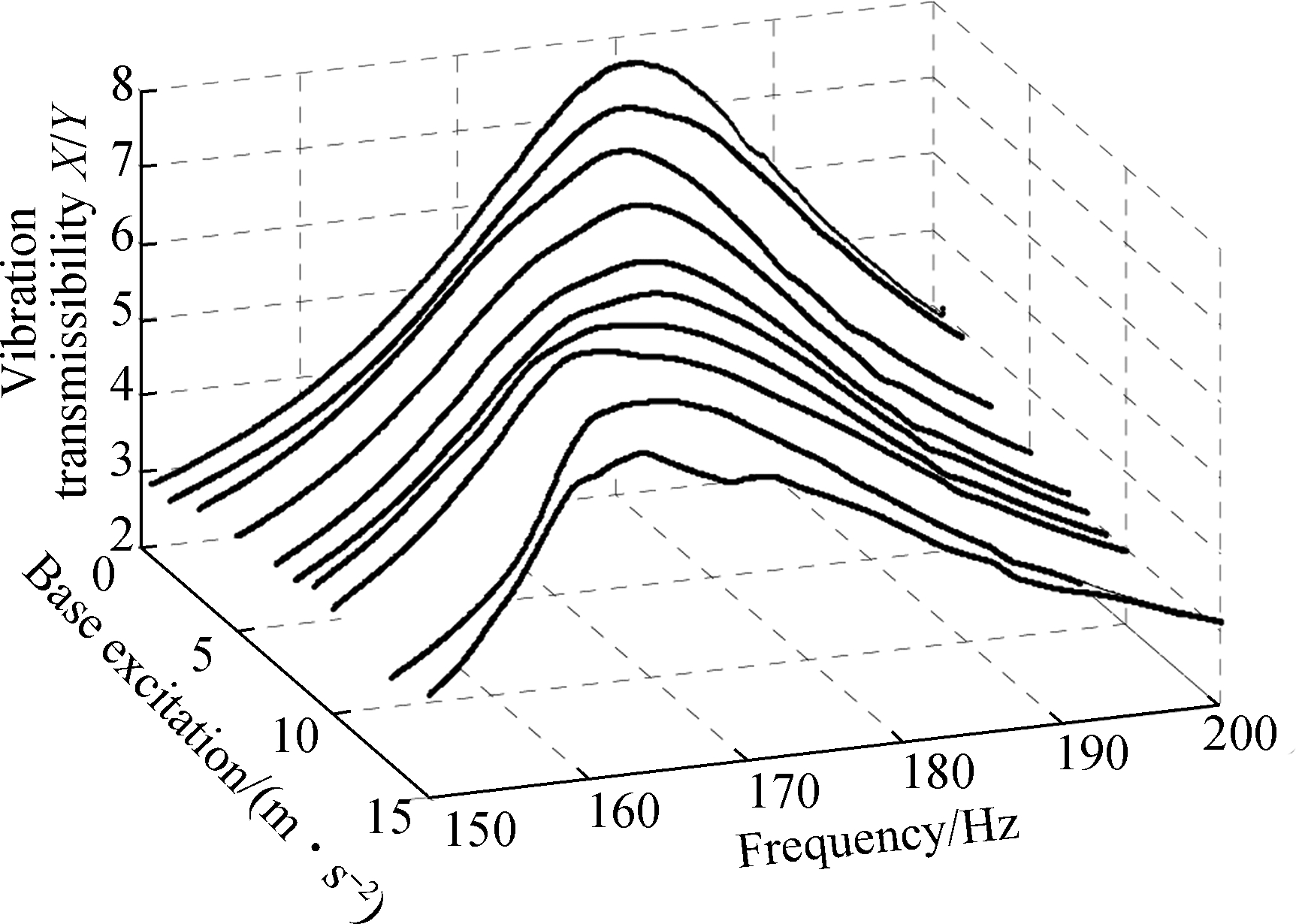
Fig.7 Vibration transmissibilities for different base excitation levels
2 Modeling and Identification
2.1 Experimental analysis
Subjected to a base excitation in the vertical direction and considering the vertical rigid motion, the mass can be considered to be an equivalent system containing a spring, viscous damper, and the equation of motion for the mass with a steady response under harmonic base excitation is
(-mw2+k+ic)X=(k+ic)Y
(1)
or
(-mw2+k+ic)Z=mw2Y
(2)
where m is the known mass of the system; k and c are the spring and viscous damping, respectively;w is the base excitation frequency; X is the displacement response amplitude of mass; Y is the base displacement response amplitude; Z is the relative displacement between mass and base and Z=X-Y.The relative transmissibility is much more important since it is directly related to the actual deformation of the structural joint.Two types of transmissibility can be introduced and the absolute transmissibility is

(3)
The other relative transmissibility is
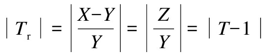
(4)
Eq.(3)presents the experimental vibration transmissibility and considering viscous damping, its mathematical expression is
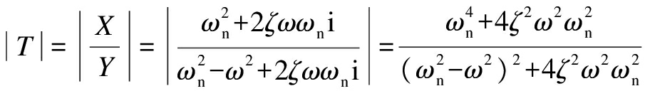
(5)
where ωn is the resonant frequency and ζ is the damping ratio of the dynamic system.
Eq.(5)is directly related to the modal information and the maximum transmissibility occurs at resonance, which is
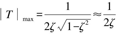
(6)
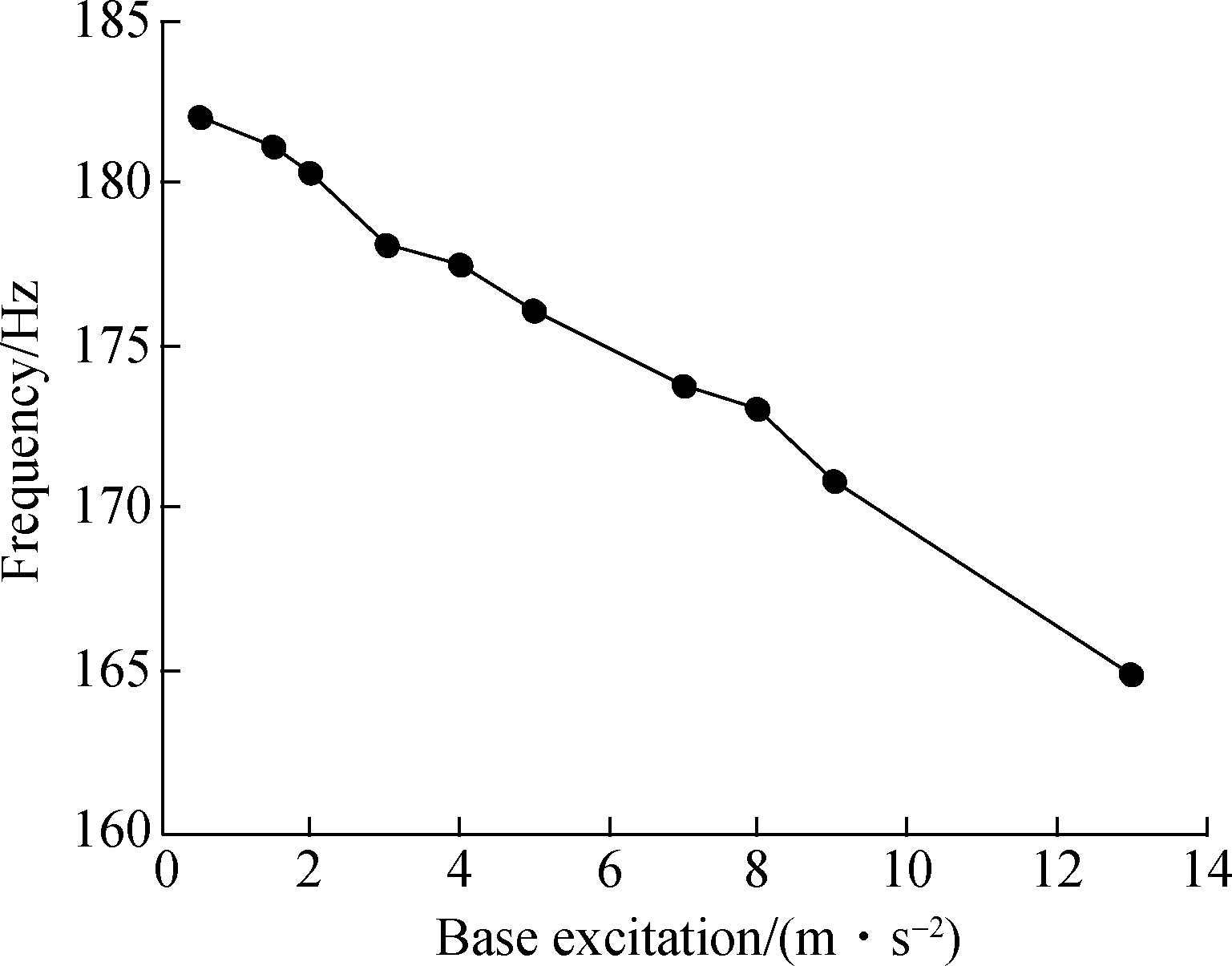
The resonant frequency and damping ratio are extracted by experimental transmissibility and they are shown in Fig.8.
As can be seen from Fig.7 and Fig.8, with the increase of excitation level, resonant frequency decreases and the damping ratio increases, which means obvious system nonlinearity along the joint boundary.It shows that the resonant frequency decreases by 10.1% and damping ratio increases by 24.2% at the highest excitation level in comparison with the lowest excitation level.If a shift in the natural frequency takes place in a jointed mass system, it can be inferred that the system must have undergone changes in structural stiffness at its joint connection, and it allows for more friction-induced slip-displacement and gives rise to more overall energy dissipation per vibration cycle for high excitation level that reveals nonlinear damping.
(a)

(b)
Fig.8 Extracted modal parameters for different base excitation levels.(a)Evolution of natural frequency with the increase of the base excitation level; (b)Evolution of the damping ratio with the increase of the base excitation level
2.2 Numerical modeling
According to Refs.[11-12], the joint part usually has multiple nonlinearities that contain a softening stiffness and hardening damping due to the slip or tap at the contact region and the modal quantity can be considered to be dependent on several factors due to its inherent nonlinearity or different boundary conditions, such as vibration response amplitude, excitation frequency range or temperature etc.The experimental data shows that the dominant mode is well separated from other resonances, so it needs to define a governing function representing the bolted joint interface for system parameters identification.Subjected to a base excitation, the assumed model that contains the linear spring, viscous damper and corresponding nonlinear part is shown in Fig.9.
M![]() k2(x-y)3+k3(x-y)3|x-y|=0
k2(x-y)3+k3(x-y)3|x-y|=0
(7)
If the mode is normalized, the mass is unified, and it can be used for numerical modeling to describe the nonlinear characteristics of the joints.Given the relative displacement between the mass and base as z=x-y and supposing a mass motion as x=X sinωt, and ![]() and
and ![]() Eq.(7)is rewritten as
Eq.(7)is rewritten as
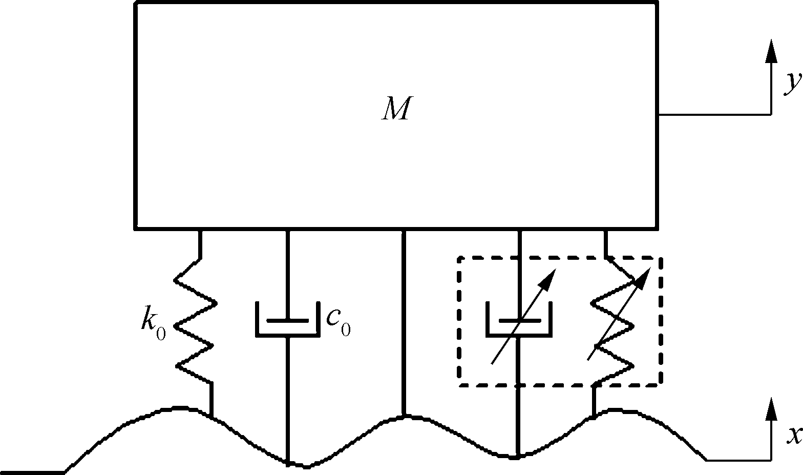
Fig.9 Schematic of SDOF system considering vertical motion under base excitation
![]() λ1z|z|+λ2z3+λ3z3|z|=Yω2sinωt
λ1z|z|+λ2z3+λ3z3|z|=Yω2sinωt
(8)
where the non-dimensional parameters can be presented as
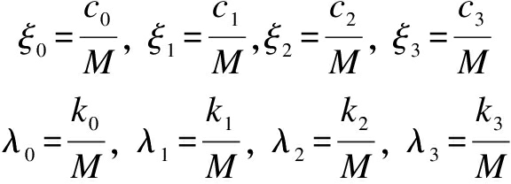
(9)
For a weak nonlinear system, the energy of the nonlinear system is concentrated in the excitation frequency and the primary harmonic response is dominant, so that super-harmonics and the sub-harmonics can be ignored.The steady-state solution of Eq.(8)based on the harmonic balance method with the first-order approximation is assumed in the form as
z(t)=Zsinφ=Zsin(ωt+φ)
(10)
where φ is the phase;φ=ωt-φ; Z is the relative displacement amplitude between the base and the mass.
Let

(11)
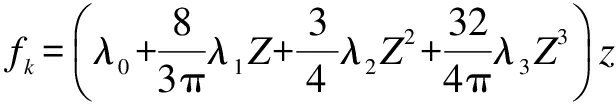
fk=λ0z+λ1z|z|+λ2z3+λ3z3|z|
(12)
Substituting Eq.(10)into fc and fk, it yields
fc=ξ0Zωcosφ+ξ1Z2cosφ|cosφ|+ξ2Z3ω3cos3φ+ ξ3Z4ω4cos4φ
(13)
fk=λ0Zsinφ+λ1Z2sinφ|sinφ|+λ2Z3sin3φ+ λ3Z4sin4φ
(14)
The function fc and fk can be approximated by Fourier expansion up to the first order as

(15)
(16)
Therefore, following the HBM with the first-order expansion, the nonlinear element induced by the nonlinear mechanisms due to joints can be defined as the function of relative displacement amplitude, and the modal stiffness and damping coefficient under normalized mass can be written as
(17)
(18)
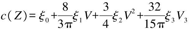
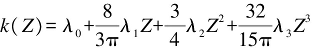
where V=ωZ is the relative velocity; ![]() and fk=k(Z)z.Then, nonlinear force can be depicted as a polynomial form as the function of relative displacement or velocity.Therefore, Eq.(8)can be rewritten as
and fk=k(Z)z.Then, nonlinear force can be depicted as a polynomial form as the function of relative displacement or velocity.Therefore, Eq.(8)can be rewritten as
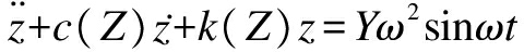
(19)
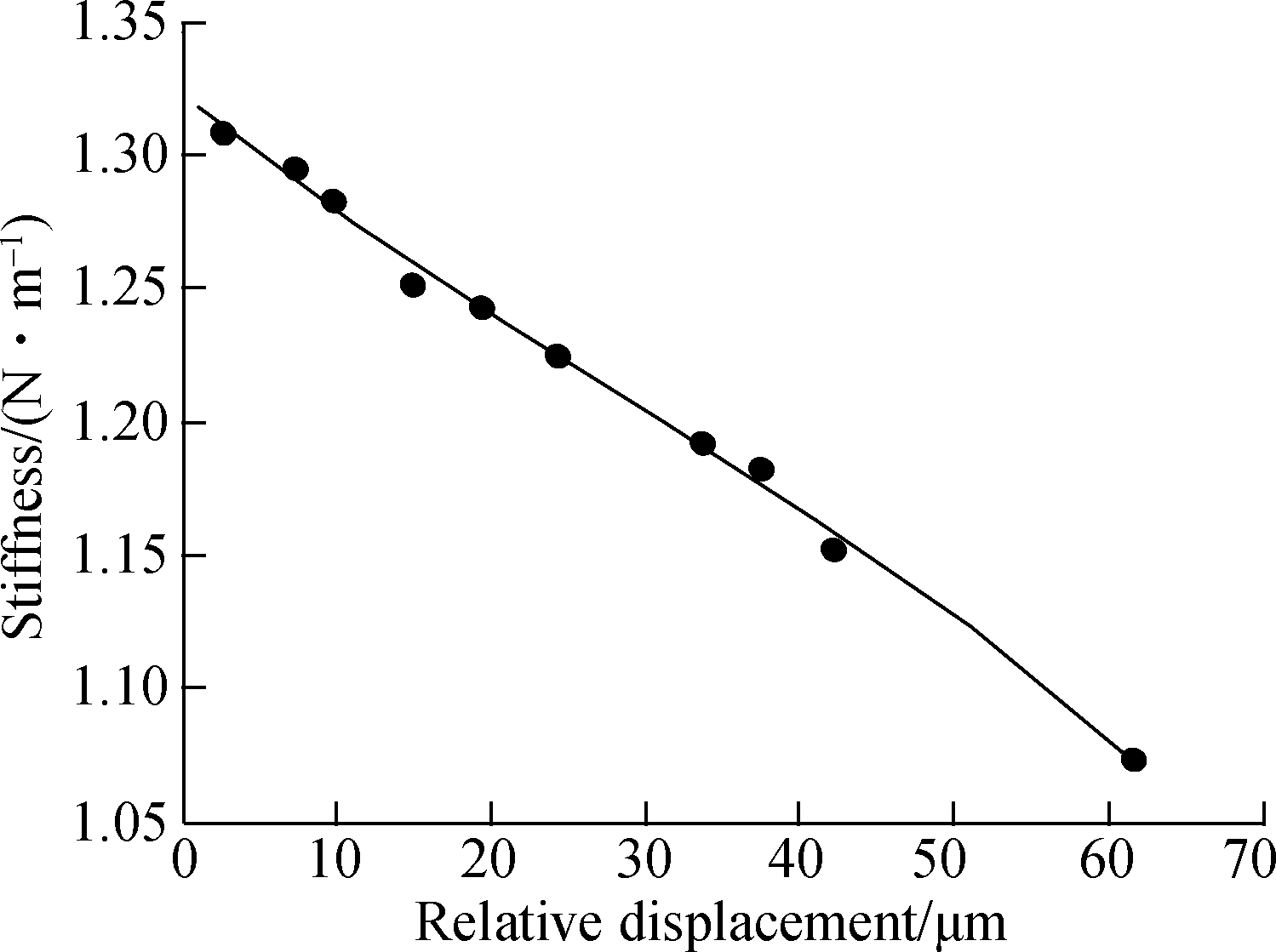
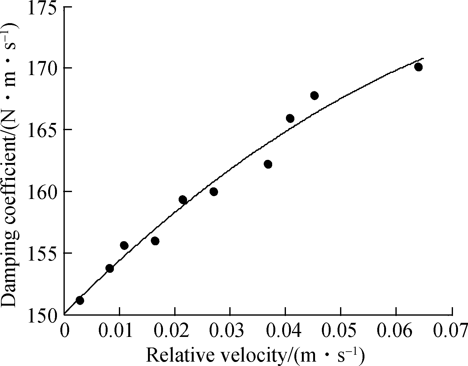
Transmissibilites have been obtained for different base excitation levels(see Fig.7), and the system’s stiffness and damping can be calculated from the vibration transmissibilities.If the stiffness and damping element corresponding to each relative response amplitude is obtained, all these elements can be fitted as a function of the relative response amplitude, as shown in Fig.10(a)and Fig.10(b), which can be employed to detect the type of a nonlinear element according to its variation trend.The results can be used to describe the nonlinear effect and regarded as representations of internal nonlinear forces in the system.
(a)
(b)
Fig.10 Equivalent stiffness and damping as a function of response.(a)Calculated stiffness as a function of relative displacement; (b)Calculated damping as a function of relative velocity
The equivalent stiffness and damping function of the relative response have been defined for each base excitation level as above and the fitting results are as follows:
k(Z)=1.322e6-4.661e9Z+3.748e13Z2-6.535e17Z3
(20)
c(V)=150.8+314.7V+3048V2-4.991e4V3
(21)
Then, Eqs.(20)and (21)are compared with the equivalent analytical function Eqs.(17)and (18)that are derived from the harmonic balance method only considering the fundamental responses.According to the function representation of the nonlinearity, by the function of relative response, parametric identification of the type of nonlinearity in a structural joint can be conducted.Also, the linear and nonlinear elements in the assumed joint mode Eq.(8)can be obtained as ξ0=1.322×10⁶, ξ1=-5.49×10⁹, ξ2=4.997×10¹³,ξ3=-9.649×10¹⁷,λ0=150.8, λ1=370.6, λ2=4 064, λ3=7.346×10⁴, which is used for linear and nonlinear modal parameter identification.Although the identified results are simple and cannot reflect the physical essence of micro or macro slip at the interface, they represent an accurate model instead of a complex one[11-14].
It can be employed to predict the vibration response at the given excitation level for experimental observations.The proposed joint model considering nonlinear stiffness and damping force is used to predict the experimental observations presented in Fig.11 for 0.5, 7 and 11 m/s2 base excitation.The results show that the response predictions obtained by using the identified parameters in vicinity of resonances are in good agreement with the experimental and predicted responses.The experimental measured responses are also demonstrated in Fig.11, which show that the method has the ability to identify system parameters within a certain weak range with certain ideal accuracy.The identified nonlinear force in Eqs.(15)and (16)can be represented by polynomial order approximation instead of the unduly complex one.Note that the fitting result by vibration transmissibilities and its mathematical model is only sufficient to respond to a nonlinear property within a certain range and a broader range of excitation values far away from the tuning region is not recommended, which will cause a larger error.
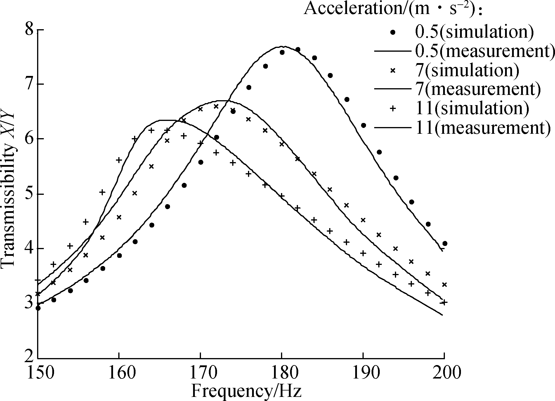
Fig.11 Measured and simulated transmissibilities for 0.5, 7 and 11 m/s2
3 Conclusions
1)The structural joint system and its uncertainty boundary usually result in nonlinear behavior that can be observed by the drastic shift in natural frequency or the response peak.Meanwhile, lower pretension will decrease the stiffness and give rise to greater frictional damping capacity and lead to stronger nonlinearity and uncertainty for low pretension contrition.
2)The standard vibration test is conducted for different base excitation levels and experimental results based on vibration transmissibiities are obtained for nonlinear identification.Obtained parameters can be fitted with a suitable basis function of the response displacement over the turning excitation range.Its application has been illustrated by a real mass joined to the shaking table and it can be used to describe the nonlinearity of the vertical motion mode.
3)According to the harmonic balance method, the nonlinear element of the assumed joint model can be characterized.Moreover, it is confirmed that a higher-order type nonlinear spring and damping force dependent upon the relative vibration amplitude can be used to describe the nonlinearity of a structural joint with a certain accuracy.It has been validated that vibration response prediction is in good agreement with the curves measured by numerical analysis.
References
[1]Eriten M, Kurt M, Luo G, et al.Nonlinear system identification of frictional effects in a beam with a bolted joint connection[J].Mechanical Systems and Signal Processing, 2013, 39(1): 245-264.DOI:10.1016/j.ymssp.2013.03.003.
[2]Cai L.Review on dynamic properties of bolted joints[J].Journal of Mechanical Engineering, 2013, 49(9): 158.DOI:10.3901/jme.2013.09.158.
[3]Luo L, Sun B B, Chen H X.Parametric modeling and lightweight optimization for cross beam of punch based on grid deformation and agent model[J].Journal of Southeast University (Natural Science Edition), 2015, 45(1):56-62.DOI:10.3969/j.issn.1001-0505.2015.01.011.(in Chinese)
[4]Chen C S, Wang Q, Liu R F, et al.Effect of bolt connection on structural vibration modes and transfer characteristics[J].Journal of Vibration & Shock, 2014, 33(12):42-47.(in Chinese)
[5]Luan Y, Guan Z Q, Cheng G D, et al.A simplified nonlinear dynamic model for the analysis of pipe structures with bolted flange joints[J].Journal of Sound and Vibration, 2012, 331(2): 325-344.DOI:10.1016/j.jsv.2011.09.002.
[6]Wang Y, Li F M.Nonlinear dynamics modeling and analysis of two rods connected by a joint with clearance[J].Applied Mathematical Modelling, 2015, 39(9): 2518-2527.DOI:10.1016/j.apm.2014.10.056.
[7]Cai L.Identification of nonlinear joint parameters with force-state mapping method[J].Journal of Mechanical Engineering, 2011, 47(7): 65-72.DOI:10.3901/jme.2011.07.065.
[8]Wei H T, Kong X R, Wang B L, et al.Non-linear dynamic response of a beam with bolted joint based on modal shape transfer[J].Journal of Vibration & Shock, 2014, 33(12):42-47.(in Chinese)
[9]Heller L, Foltête E, Piranda J.Experimental identification of nonlinear dynamic properties of built-up structures[J].Journal of Sound and Vibration, 2009, 327(1): 183-196.DOI:10.1016/j.jsv.2009.06.008.
[10]Guo H, Zhang J, Liu R, et al.Effects of joint on dynamics of space deployable structure[J].Chinese Journal of Mechanical Engineering, 2013, 26(5): 861-872.DOI:10.3901/cjme.2013.05.861.
[11]Jalali H, Ahmadian H, Mottershead J E.Identification of nonlinear bolted lap-joint parameters by force-state mapping[J].International Journal of Solids and Structures, 2007, 44(25): 8087-8105.DOI:10.1016/j.ijsolstr.2007.06.003.
[12]Ahmadian H, Jalali H.Identification of bolted lap joints parameters in assembled structures[J].Mechanical Systems and Signal Processing, 2007, 21(2): 1041-1050.DOI:10.1016/j.ymssp.2005.08.015.
[13]Liu X, Sun B, Xue F, et al.Identification of nonlinear parameter of mechanical joint system based on vibration tests[J].Journal of Vibration Engineering and Technologies, 2016, 4(5):475-482.
[14]Wang J M, Zheng C L.Nonlinear analytical modeling and analysis for bolted joint structures[J].Journal of Vibration and Shock, 2013, 32(20):5-8.(in Chinese)