Over the past several decades, much attention has been given to the vibration control in civil engineering structures subjected to earthquakes and winds.Various semi-active control systems, which combine the best features of both passive and active control systems, have been proposed and studied.Among the semi-active control devices, the magnetorheological (MR)damper has become one of the most promising control devices for vibration mitigation in civil engineering, automobile engineering and other areas, due to its advantages of low power requirement, quick response and large damping force.Recognizing the significant potential of the MR damper, a number of researchers have undertaken this to study[1-8].
To evaluate the usefulness and control effect of MR dampers in structural response reduction, a mathematical model of the MR damper should be established.In recent years, many high fidelity models have been proposed, which can be generally classified into two categories.The first kind of models are deduced based on the constitutive model of MR fluid and the Navier-Stokes equation.These models can be used to calculate the damping force conveniently[9-12], but they cannot describe the force-velocity hysteretic characteristics.Also, the yield shear stress of the MR fluid under different magnetic fields should be known first.The other kind of models are the hysteresis operator-based parametric models[13-17], of which the parameters can be identified using the performance test data on the MR damper.These models are comprehensively summarized and compared by Wang and Liao[18], and they can effectively portray both the force-displacement and force-velocity hysteresis characteristics with high predicting accuracy.Many of them have been employed in practical vibration reduction engineering using the MR damper.
However, due to the relatively high viscosity of the MR fluid, eliminating air pockets in the MR damper and the air dissolved in the MR fluid is very difficult, and the trapped air in the MR fluid will reduce the compressibility of the MR fluid and result in a force lag in MR damper responses.This phenomenon was first found by Yang[19], yet information is very limited and there is no additional analysis on the trapped air effect on the MR damper.In order to account for the compressibility of magnetorheological fluid due to the trapped air, Guo et al.[20] proposed a physical model by establishing the flow rate equations for two chambers, which can be used to simulate the force lag phenomenon due to the trapped air, and it is verified using the experimental data[19].However, the derivation process is very complex and the model is not convenient for use in the semi-active control system to evaluate the control effect considering the trapped air in the MR fluid.
In this study, the performance test on a MR damper is carried out to acquire the performance characteristics under different loading cases, unexpectedly to find the same force lag phenomenon in the force-displacement and force-velocity hysteresis curves.The influences of the loading cases, including current, displacement amplitude and frequency, on the force lag phenomenon are discussed in detail.Also, a concise and efficient parametric model, combining the simple Bouc-Wen model and a spring with small stiffness, is proposed to capture the force-lag phenomenon of the MR damper, and the parameters are identified using the experimental data of the MR damper.As the trapped air will deteriorate the damper’s performance, a single-degree-of-freedom (SDOF)structure is employed to evaluate the performance of a semi-active control system based on the MR damper considering trapped air effect, and the dynamic responses of the semi-active controlled SDOF are calculated based on the acceleration feedback control strategy.
1 Experimental Setup and Sinusoidal Response
1.1 Experimental description
The MR damper employed in this study is in mix mode with five coils, and the schematic of the damper is shown in Fig.1.The whole length of the damper is 1 150 mm, and the main cylinder has an inner diameter of 160 mm and an outer diameter of 194 mm.The main cylinder houses the piston, the magnetic circuit and MR fluid, and the damper has a ±50 mm stroke.The damping gap is 2 mm and the effective damping length is 250 mm.
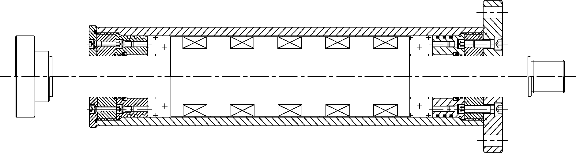
Fig.1 Schematic of MR damper
To acquire the damping characteristics of the MR damper, the performance test is carried out to obtain the force-displacement and force-velocity hysteresis curves under sinusoidal excitation.In each test, the hydraulic actuator was driven with a sinusoidal signal and a fixed frequency, amplitude and current.A wide range of currents, frequencies and amplitudes are considered in this study.The input currents are 0, 0.6, 1.2, 1.8, 2.1 and 2.4 A, respectively; the displacement amplitudes are 10, 20, 30 and 40 mm, respectively; the excitation frequencies are 0.1 and 0.2 Hz.
1.2 Result and analysis
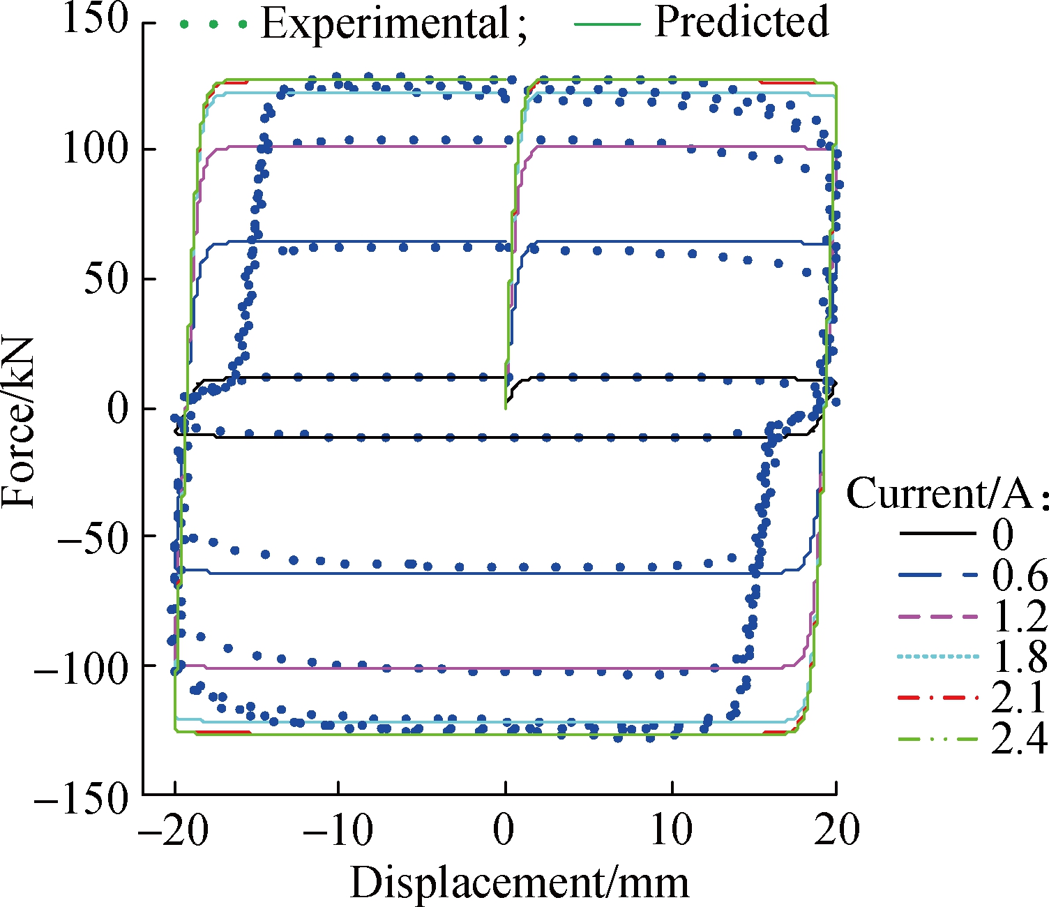
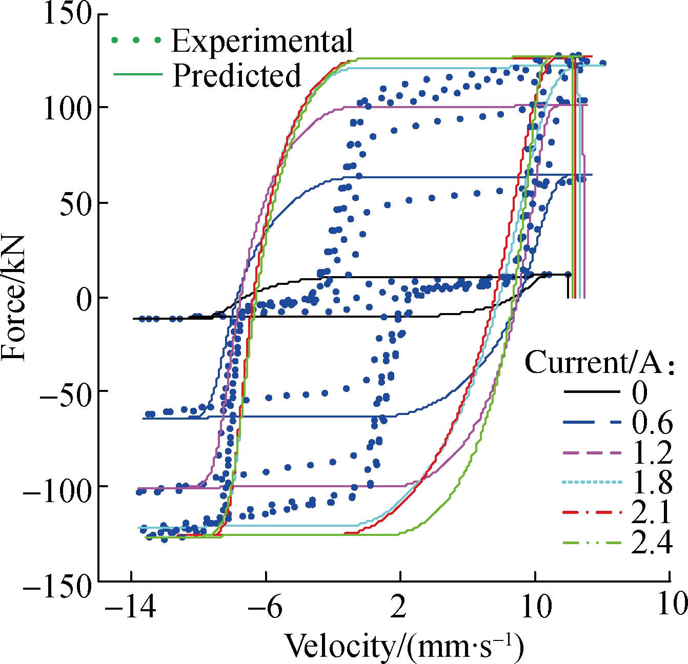
The displacement and force data were sampled and collected, and the velocity response was calculated from the measured displacements via differential approximation.Based on the experimental data, the hysteresis characteristics are discussed in detail.Fig.2 shows the experimental results for 0.1 Hz sinusoidal excitation with an amplitude of 20 mm under different input currents.It can be seen that the damping forces increase with the increase of input currents.The maximum and minimum damping forces are 128.2 and 12.23 kN when the current ranges from 0 to 2.4 A, respectively, which shows the good adjustability of the MR damper.It can be also seen that there is a force lag phenomenon in the force-displacement and force-velocity hysteresis curves when the piston begins to move in the reverse direction, which is caused by the trapped air in the MR fluid according to the research of Yang[19].Also, the force lag will be more obvious when the content of air increases.Due to the content of air trapped in the MR fluid being comparatively smaller in this experiment, the force lag phenomenon is less obvious than that in the experimental results of Yang[19].Specifically, the stiffness is larger and the distance is smaller in the force lag part.From Fig.2, it can be also seen that the stiffness and distance are nearly the same under different input currents, and these two parameters can be used to describe the force lag characteristics.

(a)
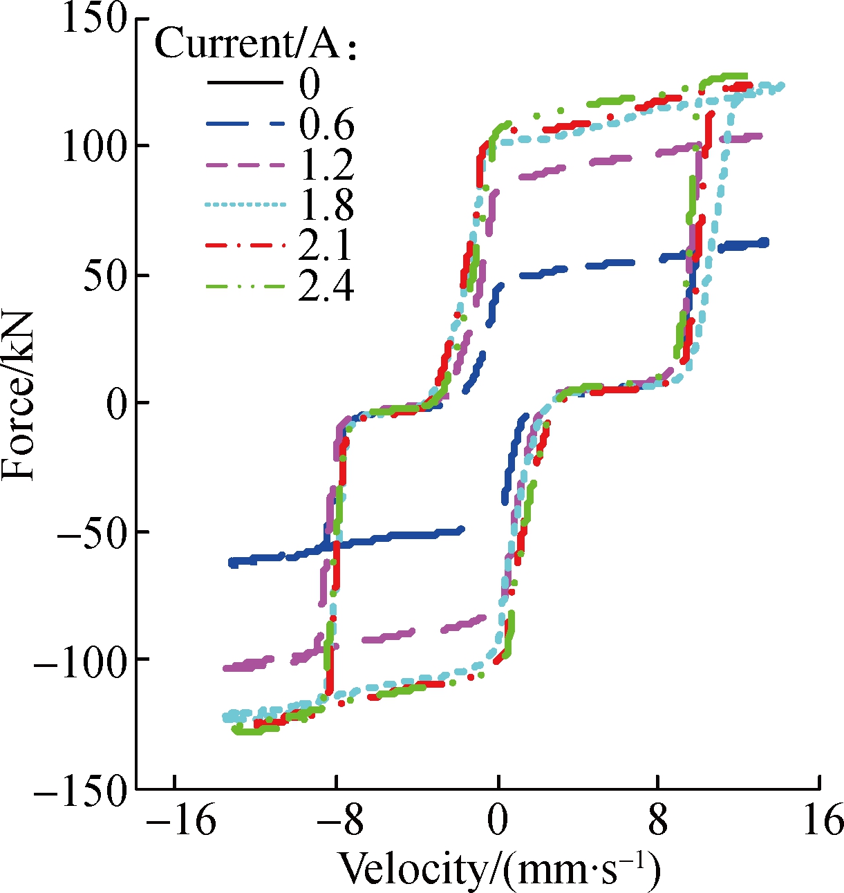
(b)
Fig.2 Experimental result for 0.1 Hz sinusoidal excitation with an amplitude of 20 mm under different currents.(a)Force-displacement curves; (b)Force-velocity curves
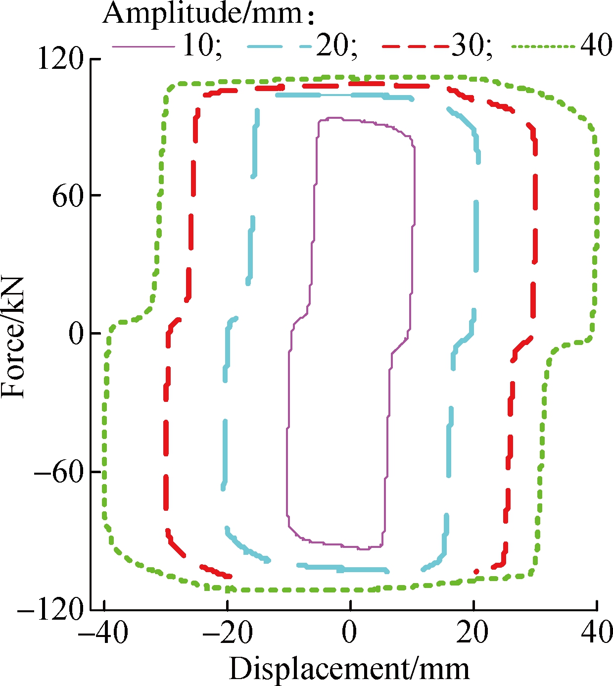
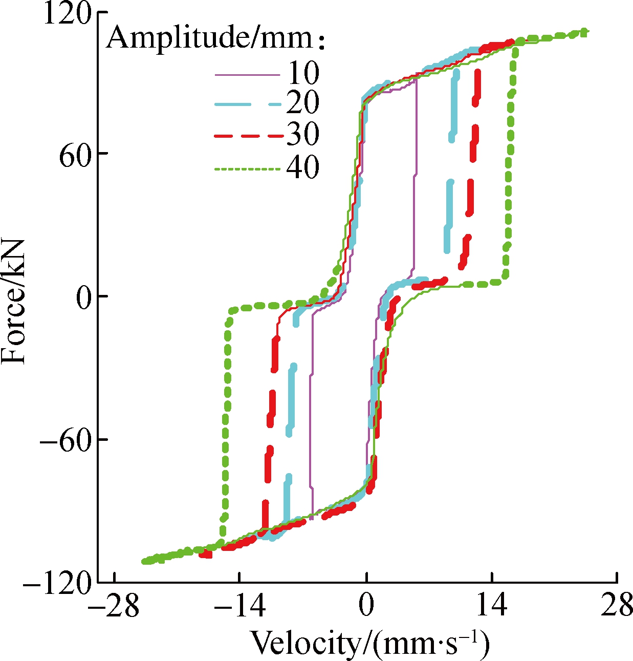
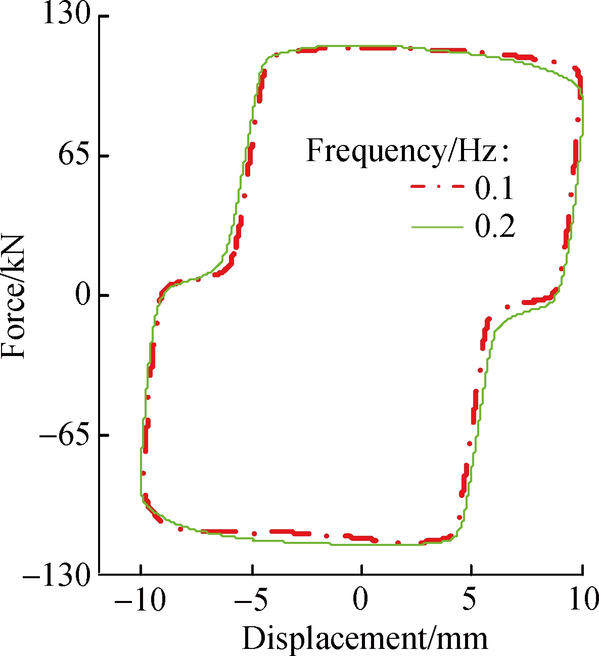
Fig.3 shows the experimental results for 0.1 Hz sinusoidal excitation with a current of 1.2 A under different displacement amplitudes.It can be seen that the damping force increases slightly with the increase in amplitude.The distance and the stiffness in the force lag part vary very slightly and they are nearly the same when the amplitude ranges from 10 to 30 mm.The force lag is a little more obvious when the amplitude is 40 mm, that is, the stiffness becomes smaller and the distance becomes larger.These results show that the displacement amplitude influences the force lag phenomenon very slightly.Fig.4 shows the experimental results for 10 mm sinusoidal excitation with a current of 2.4 A under different frequencies.It can be seen that the maximum damping forces are almost nearly the same when the frequency ranges from 0.1 to 0.2 Hz, with a maximum damping force of 115.7 and 117.1 kN, respectively.
(a)
(b)
Fig.3 Experimental result for 0.1 Hz sinusoidal excitation a current of 1.2 A under different amplitudes.(a)Force-displacement curves; (b)Force-velocity curves
2 Modelling of MR Damper Considering Trapp-ed Air Effect
To evaluate the control effect of the MR damper in response reduction of civil structures subjected to the seismic excitation considering trapped air effect, a model should be established to describe the characteristics of the MR damper.According to the above discussion of the MR damper, there is a force lag compared with the common experimental results.From the force-displacement hysteresis curves, the force lag part works as a spring with small stiffness, and the other part is the same as common experimental results and can be described using the widely used dynamic model, such as the Bouc-Wen hysteresis operator-based dynamic model[21-22].Thus, the hysteresis characteristics considering trapped air effect can be simulated by combining the spring with the widely used dynamic parametric model properly.Herein, a simple Bouc-Wen model is employed, of which the force is given by
(a)

(b)
Fig.4 Experimental result for 10 mm sinusoidal excitation with a current of 2.4 A under different frequencies.(a)Force-displacement curves; (b)Force-velocity curves
(1)
where the evolutionary variable z is governed by
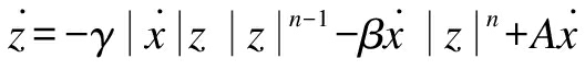
(2)
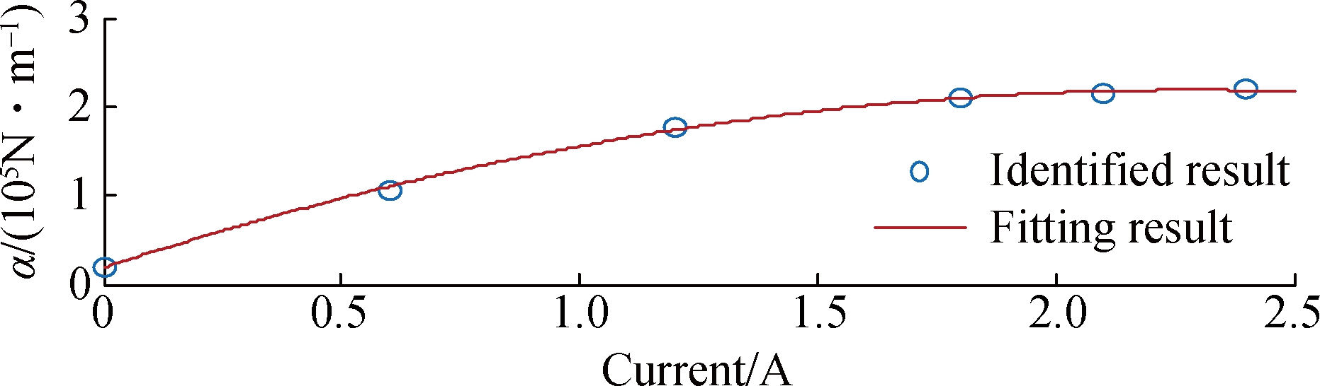
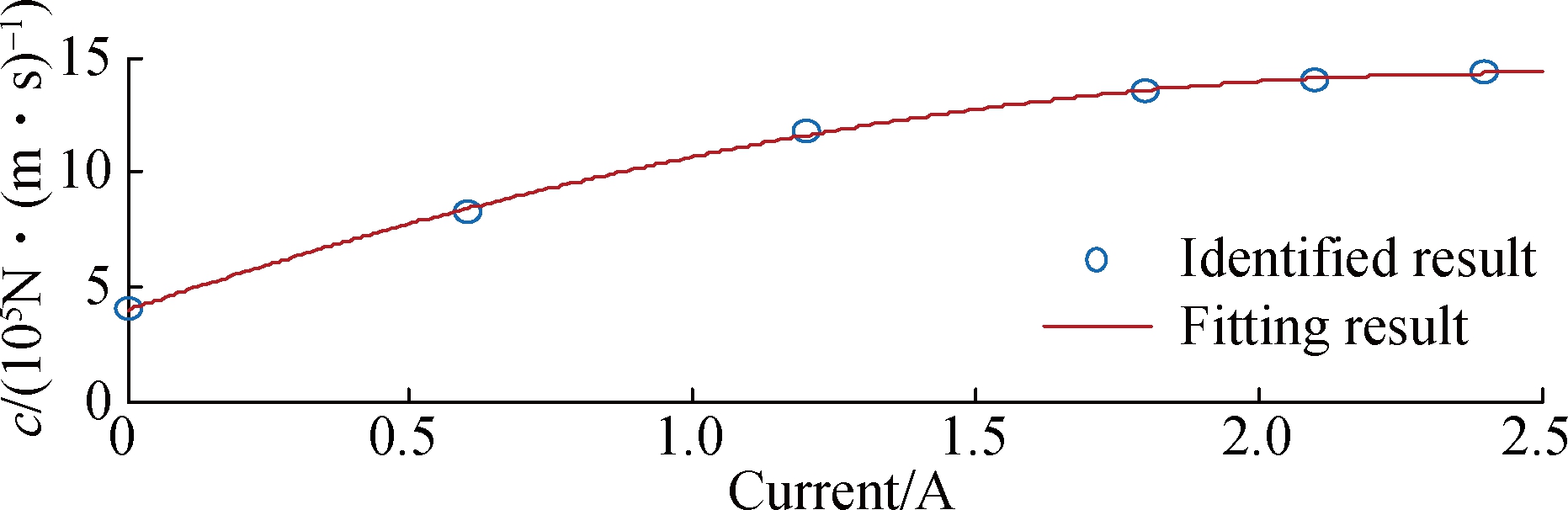
By adjusting the parameters of the model γ, β and A, one can control the shape of the hysteresis loops for the yielding element.Then, the parameters are identified by using the nonlinear least squares optimization method.According to the identified results, the input current has a great influence on the parameters α and c, yet the amplitude and frequency affects the parameters only slightly and this is ignored in this study to avoid too many coefficients.Due to a 0.1 Hz sinusoid with an amplitude of 20 mm, the correlation between the two parameters and the current is identified, as shown in Fig.5.It can be seen that the values of α and c increase with the increase in current and then almost maintain the same when the current exceeds 2.1 A.Thus, to account for the dependence of the force on the current, the following equations are suggested:
α=α1I2+α2I+α3
(3)
c=c1I2+c2I+c3
(4)
where I is the current applied to the MR damper.The parameters of the model are chosen to be γ=1 200 m-2, β=1 200 m-2, A=800, n=2, α1=-3.824×10⁴ N/(m·I2), α2=1.749×10⁵ N/(m·I), α3=1.876×10⁴ N/m, c1=-1.7×10⁴ (N·s)/(m·I2), c2=8.387×10⁴ (N·s)/(m·I), c3=3.964×10⁴ N/(s·m).A comparison between the predicted responses and the corresponding experimental data is provided in Fig.6.It can be seen that the model can predict the force-displacement and force-velocity curves well disregarding the force lag part.In order to consider the trapped air effect, a spring with small stiffness is employed to simulate the force lag part, and then the key point is to define the scope that the spring works, that is, to determine the starting and ending condition.According to the tested results, the spring works when the piston of the damper achieves the maximum displacement and starts to move in the reverse direction, and the following equation can be used to determine the start time,
F(i)F(i-1)≤0
(5)
where F(i)represents the current damping force of the damper calculated by using the simple Bouc-Wen model; F(i-1)represents the damping force of the final step.
(a)
(b)
Fig.5 Identified and fitting results of the parameters with respect to current.(a)Value of α; (b)Value of c
From the experimental results, it can be also seen that the spring only works in a limited distance before all the air bubbles closed.Herein, the force lag distance is adopted to determine the end time.If the piston keeps moving in the same direction, then the end time within that the spring works can be defined when the piston displacement satisfies the following equation:
(a)
(b)
Fig.6 Comparison between predicted and experimentally obtained responses for the simple Bouc-Wen model with a 0.1 Hz sinusoidal excitation and an amplitude of 20 mm under different currents.(a)Force-displacement curves; (b)Force-velocity curves
|x-x(i)|≥d
(6)
where x(i)is the latest displacement value when the piston starts to move in the reverse direction; x is the displacement of the current step; d is the force lag distance.
Thus, the damping force can be calculated linearly using the following equation when the spring works:
F=k(x-x(i))
(7)
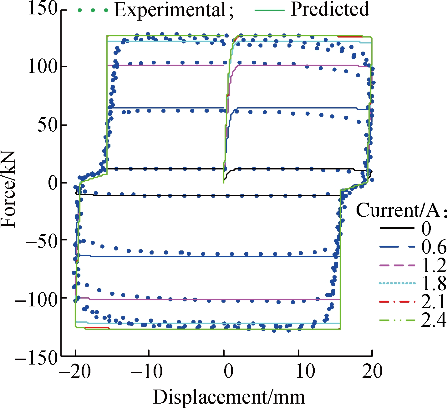
A comparison between the predicted and experimental results is shown in Fig.7.It can be seen that the proposed model can effectively portray the force lag phenomenon.Herein, the stiffness k is chosen to be 2×10⁶, and the force lag distance d is chosen to be 3.5 mm.Note that the two parameters, that is the stiffness and force lag distance, change with different contents of the trapped air.The more the air trapped in the MR fluid, the longer the force lag distance and the smaller the stiffness value.Thus, the values of the two parameters can be adjusted to evaluate the performance of the semi-active control system considering different contents of trapped air.
3 Numerical Example
The influence of the trapped air on the semi-active control effect is evaluated through numerical simulation.For a semi-active controlled structure subjected to external excitation, the motion equation can be written as
(a)

(b)
Fig.7 Comparison between predicted and experimentally obtained responses for the proposed model considering the trapped air effect with a 0.1 Hz sinusoidal excitation and an amplitude of 20 mm under different currents.(a)Force-displacement curves; (b)Force-velocity curves
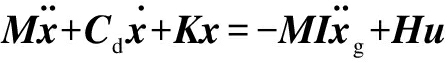
(8)
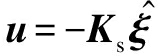
where M, Cd, K are the mass, damping and stiffness matrix of the structure; x is the displacement ![]() is the external excitation; H is the location matrix of the control device; u is the control force vector.For convenience of using the state space method to solve the equation, the above equation can be rewritten in the state space form as[23]
is the external excitation; H is the location matrix of the control device; u is the control force vector.For convenience of using the state space method to solve the equation, the above equation can be rewritten in the state space form as[23]
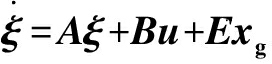
(9)
(10)
(11)
where ![]() is the state vector; z is the output vector; y is the measurement vector; ζ is the measured noise vector.
is the state vector; z is the output vector; y is the measurement vector; ζ is the measured noise vector.
In practical vibration reduction, the absolute acceleration is easy to measure, but the accurate measurement of the displacement and velocity are difficult to achieve.Thus, the LQG controller[24-25] is adopted here to reduce the structural responses, in which the performance index is given as
J=![]() (ξΤQξ+uΤRu)dt
(ξΤQξ+uΤRu)dt
(12)
where Q and R are the weighting matrices and can be used to adjust the controller to obtain the desired control effect.
The control force can be written as[25]
(13)
where Ks is the full state feedback gain matrix; ![]() is the state vector predicted by using the Kalman filter, which can be written as
is the state vector predicted by using the Kalman filter, which can be written as
(14)
where L is the observer gain matrix of the stationary Kalman filter.
However, differing from the active control system, the control force provided by the MR damper can only be changed through the input current and cannot generate the optimal control force at any time.Thus, the classical clipped-optimal control strategy[2] is adopted, which can be expressed by the following equation:
I=ImaxH{(fd-f)f}
(15)
where Imax is the maximum input current; H{·} is the unit step function; fd is the optimal control force; f is the current control force provided by the MR damper.The strategy shows that the current will remain the same when the control force provided by the damper is equal to the optimal control force; if the provided force is smaller than the optimal control force in the same direction, the current will be increased to the maximum current to increase the damping force.
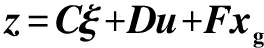
Herein, a semi-active controlled SDOF structure is employed to evaluate the control effect considering the trapped air in the MR fluid.The structural parameters are 3×10⁴ kg of the mass and 1.5×10⁷ N/m of the stiffness.The damping ratio is selected to be 5%.The band-limited white noise is selected as the external excitation, of which the power spectrum density is 0.2.The dynamic responses are calculated using Matlab/Simulink, and the flow chart of the Simulink model is shown in Fig.8.
Fig.8 Flow chart of the Simulink model
The time responses for the displacement, velocity and acceleration of the controlled and uncontrolled SDOF structure are shown in Fig.9, where semi-active 1 uses the proposed model considering trapped air effect for semi-active control; semi-active 2 uses the simple Bouc-Wen model for semi-active control.The proposed model is employed to consider the trapped air effect and the pure simple Bouc-Wen model is employed for comparison.It can be seen that the MR damper can effectively reduce the dynamic responses of the structure by using the clipped-optimal control strategy, and the responses considering the trapped air is a little larger than that without considering trapped air, which shows that the trapped air can weaken the control effect of the MR damper.Quantitatively, the peak displacement and acceleration of the uncontrolled structure are 0.022 3 m and 11.184 5 m/s2, respectively, and the corresponding peak values of the semi-active control are 0.010 6 m and 5.748 1 m/s2 with a reduction of 52.47% and 54.51%.However, if considering the trapped air effect, the peak responses value are 0.011 7 m and 6.336 7 m/s2, achieving a reduction of 47.53% and 43.34% of the displacement and acceleration responses, respectively.The semi-active control effect is reduced by 4.94% and 11.17%.This is mainly because the damper cannot generate enough damping force in the force lag part due to the trapped air in the MR fluid.
Additionally, with the increasing air content, the force lag displacement d will increase and the stiffness k will decrease to a much smaller value.Thus, to show the influence of varying air content on the semi-active control effect, structural responses with different input parameter values are calculated.In order to show the trapped air effect quantitatively and more clearly, the following performance indices are employed to evaluate the control effect:
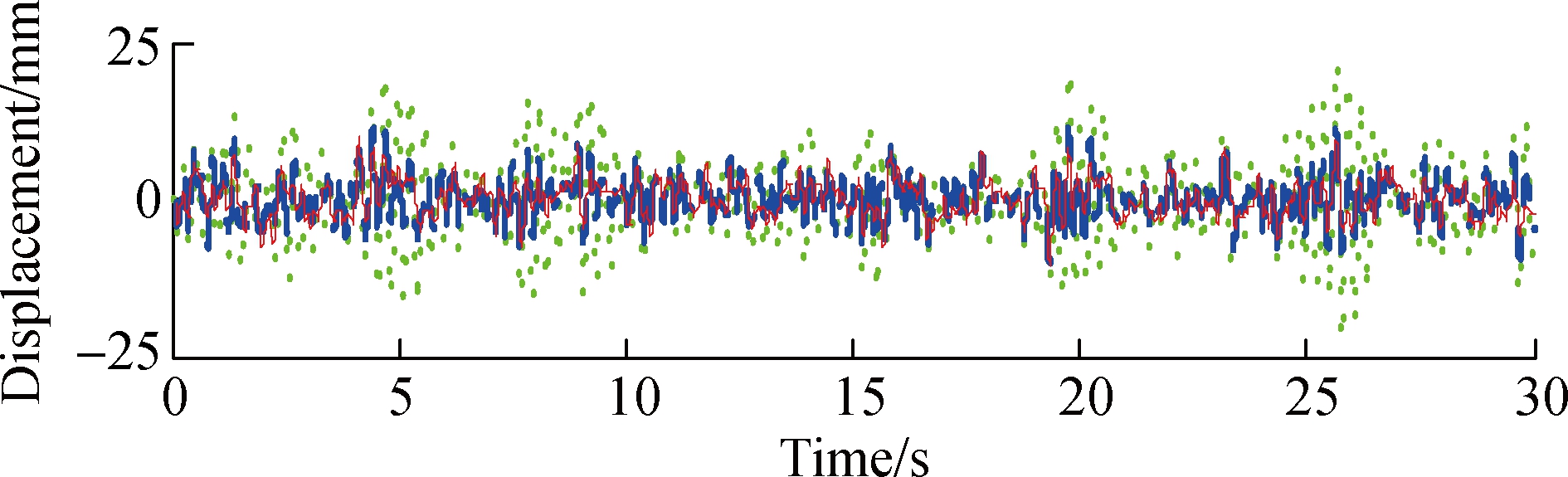
(a)
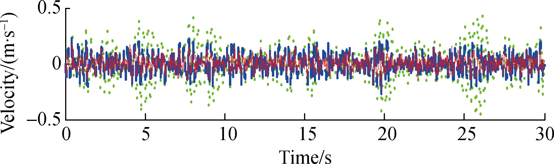
(b)
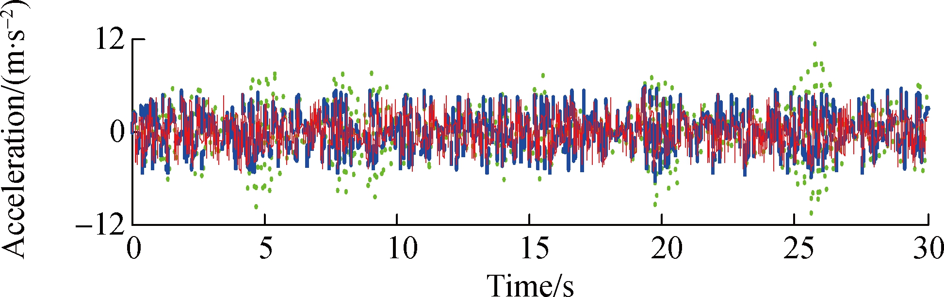
(c)![]()
Fig.9 Structural responses of uncontrolled and semi-active controlled structure subjected to band-limited white noise.(a)Displacement history curves; (b)Velocity history curves; (c)Accceleration history curves
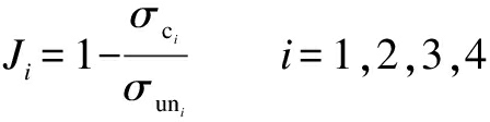
(16)
where σci and σuni (i=1,2,3,4)define the maximum displacement, maximum acceleration, root mean square (RMS)of displacement and RMS of acceleration responses of the controlled and uncontrolled structure, respectively.
As shown in Tab.1, Case 1 represents the control effect with no trapped air for comparison, and Case 2 to Case 4 represent the control effect with different air contents.Due to the reason that the accurate relationship between the trapped air content and the parameter value is unknown, the varying parameters from Case 2 to Case 4 just show an increasing trend of trapped air content.It can be seen that the performance of the semi-active control system is reduced more obviously with the increasing content of air trapped in the MR fluid.Considering the results in Case 4 with parameters k=2×10⁴, d=8 mm, the four performance indices decrease from 52.61%, 48.61%, 56.69 and 43.05 to 32.76%, 28.99%, 34.42% and 26.24%, respectively, which shows that the semi-active control effect is greatly reduced due to the trapped air in the MR fluid.
Tab.1 Performance index under semi-active control %
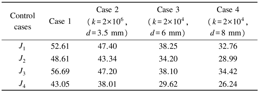
ControlcasesCase1Case2(k=2×10⁶,d=3.5mm)Case3(k=2×10⁴,d=6mm)Case4(k=2×10⁴,d=8mm)J152.6147.4038.2532.76J248.6143.3434.2028.99J356.6947.2038.1034.42J443.0538.0129.6226.24
The performance index value under passive-off control is also shown in Tab.2.It can be seen that the control effect is reduced when considering the trapped air effect, but it is not obvious compared with the results of semi-active control.Taking the maximum displacement for example, the response is reduced by 38.03% in Case 1 disregarding the trapped air effect, and the corresponding value in Case 4 is 30.11%.The control effect is weakened by 7.92% under passive-off control, which is smaller than that of the semi-active control with a value of 19.85%.On the other hand, the control effect of semi-active control is much better than that of passive-off control when there is no air trapped in the MR fluid.However, the control effect becomes very close between these two controllers with the increasing content of trapped air, as shown in Case 4.
Tab.2 Performance index under passive-off control %
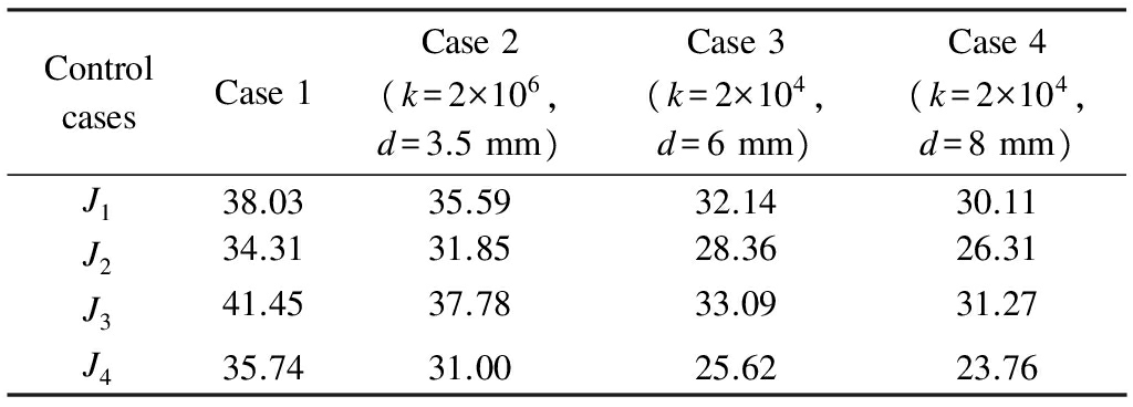
ControlcasesCase1Case2(k=2×10⁶,d=3.5mm)Case3(k=2×10⁴,d=6mm)Case4(k=2×10⁴,d=8mm)J138.0335.5932.1430.11J234.3131.8528.3626.31J341.4537.7833.0931.27J435.7431.0025.6223.76
4 Conclusions
1)Due to the high viscosity of magnetorheological (MR)fluid, eliminating air pockets dissolved in the fluid is very difficult, which will result in a force lag phenomenon.
2)A spring with small stiffness can be used to simulate the force lag part, and combining the simple Bouc-Wen model and the spring properly can well portray the experimental results of the MR damper with force lag.
3)The trapped air in the MR fluid can weaken the control effect of the MR damper, and the performance of the semi-active control system will be reduced more obviously and become close to the passive-off control with the increasing content of air trapped in the MR fluid.
References
[1]Carlson J D, Catanzarite D M, Stclair K A.Commercial magneto-rheological fluid devices [J].International Journal of Modern Physics B, 1996, 10(23): 2857-2865.DOI:10.1142/s0217979296001306.
[2]Dyke S J, Spencer B F, Sain M K, et al.Modeling and control of magnetorheological dampers for seismic response reduction [J].Smart Materials and Structures, 1996, 5(5): 565-575.DOI:10.1088/0964-1726/5/5/006.
[3]Xu Z D, Shen Y P, Guo Y Q.Semi-active control of structures incorporated with magnetorheological dampers using neural networks [J].Smart Materials and Structures, 2003, 12(1):80-87.DOI:10.1088/0964-1726/12/1/309.
[4]Xu Z D, Guo Y Q.Fuzzy control method for earthquake mitigation structures with magnetorheological dampers [J].Journal of Intelligent Material Systems and Structures, 2006, 17(10):871-881.DOI:10.1177/1045389x06061044.
[5]Xu Z D, Xu F H, Chen X.Intelligent vibration isolation and mitigation of a platform by using MR and VE devices [J].Journal of Aerospace Engineering, 2016, 29(4): 1-10.DOI:10.1061/(asce)as.1943-5525.0000604.
[6]Jung H J, Choi K M, Spencer B F, et al.Application of some semi-active control algorithms to a smart base-isolated building employing MR dampers [J].Structural Control and Health Monitoring, 2006, 13(2/3): 693-704.DOI:10.1002/stc.106.
[7]Gordaninejad F, Kelso S P.Fail-safe magneto-rheological fluid dampers for off-highway, high-payload vehicles [J].Journal of Intelligent Material Systems and Structures, 2000, 11(5): 395-406.DOI:10.1106/K90W-1A63-7QA7-6EH4.
[8]Zheng J J, Wang X J, Ouyang Q, et al.Modeling and characterization of novel magnetorheological (MR)cell with individual currents [J].Journal of Central South University, 2015, 22(7): 2557-2567.DOI:10.1007/s11771-015-2785-2.
[9]Phillips R W.Engineering applications of fluids with a variable yield stress [D].Berkeley: University of California, 1969.
[10]Wang X, Gordaninejad F.Flow analysis of field-controllable, electro-and magneto-rheological fluids using Herschel-Bulkley model [J].Journal of Intelligent Material Systems and Structures, 1999, 10(8): 601-608.DOI:10.1106/p4fl-l1el-yflj-btre.
[11]Lee D Y, Wereley N M.Quasi-steady Herschel-Bulkley analysis of electroand magneto-rheological flow mode dampers [J].Journal of Intelligent Material Systems and Structures, 1999, 10(10): 761-769.DOI:10.1106/e3lt-lyn6-kmt2-vjjd.
[12]Yang G Q, Spencer B F, Carlson J D, et al.Large-scale MR fluid dampers: Modeling and dynamic performance considerations [J].Engineering Structures, 2002, 24(3): 309-323.DOI:10.1016/s0141-0296(01)00097-9.
[13]Spencer B F, Dyke S J, Sain M K, et al.Phenomenological model for magnetorheological dampers [J].Journal of Engineering Mechanics, 1997, 123(3): 230-238.DOI:10.1061/(asce)0733-9399(1997)123:3(230).
[14]Wang E R, Ma X Q, Rakhela S, et al.Modelling the hysteretic characteristics of a magnetorheological fluid damper [J].Proceedings of the Institution of Mechanical Engineers, Part D: Journal of Automobile Engineering, 2003, 217(7): 537-550.DOI:10.1243/095440703322114924.
[15]Kwok N M, Ha Q P, Nguyen T H, et al.A novel hysteretic model for magnetorheological fluid dampers and parameter identification using particle swarm optimization [J].Sensors and Actuators A: Physical, 2006, 132(2): 441-451.DOI:10.1016/j.sna.2006.03.015.
[16]Zhou Q, Nielsen S R, Qu W L.Semi-active control of three-dimensional vibrations of an inclined sag cable with magnetorheological dampers [J].Journal of Sound and Vibration, 2006, 296(1): 1-22.DOI:10.1016/j.jsv.2005.10.028.
[17]Xu Z D, Jia D H, Zhang X C.Performance tests and mathematical model considering magnetic saturation for magnetorheological damper [J].Journal of Intelligent Material Systems and Structures, 2012, 23(12): 1331-1349.DOI:10.1177/1045389x12445629.
[18]Wang D H, Liao W H.Magnetorheological fluid dampers: A review of parametric modelling [J].Smart Materials and Structures, 2011, 20(2): 023001.DOI:10.1088/0964-1726/20/2/023001.
[19]Yang G Q.Large-scale magnetorheological fluid damper for vibration mitigation: Modeling,testing and control [D].Notre Dame: University of Notre Dame, 2001.
[20]Guo P F, Guan X C, Ou J P.Physical modeling and design method of the hysteretic behavior of magnetorheological dampers [J].Journal of Intelligent Material Systems and Structures, 2013, 25(6): 680-696.DOI:10.1177/1045389X13500576.
[21]Jansen L M, Dyke S J.Semiactive control strategies for MR dampers: Comparative study [J].Journal of Engineering Mechanics, 2000, 126(8): 795-803.DOI:10.1061/(asce)0733-9399(2000)126:8(795).
[22]Yi F, Dyke S J, Caicedo J M, et al.Experimental verification of multiinput seismic control strategies for smart dampers [J].Journal of Engineering Mechanics, 2001, 127(11): 1152-1164.DOI:10.1061/(asce)0733-9399(2001)127:11(1152).
[23]Tan P, Dyke S J, Richardson A, et al.Integrated device placement and control design in civil structures using genetic algorithms [J].Journal of Structural Engineering, 2005, 131(10): 1489-1496.DOI:10.1061/(asce)0733-9445(2005)131:10(1489).
[24]Dyke S J, Spencer B F, Quast P, et al.Role of control-structure interaction in protective system design [J].Journal of Engineering Mechanics, 1995, 121(2): 322-338.DOI:10.1061/(asce)0733-9399(1995)121:2(322).
[25]Dyke S J, Spencer B F, Quast P, et al.Acceleration feedback control of MDOF structures [J].Journal of Engineering Mechanics, 1996, 122(9): 907-918.DOI:10.1061/(asce)0733-9399(1996)122:9(907).