The flat grid structure consisting of a number of tension and compression bars connected at the joints has been widely used to construct industrial buildings, airplane hangar facilities, and public buildings due to its simple construction and better performance of the comprising members[1].Due to the intended purpose of this type of structures, suspended cranes are often used.These cranes generate repeated loading to the joints of the grid structure, especially those at the bottom chord.The fatigue failure at a joint can result in a structural collapse.For example, the grid structure of a plant in Datong City in Shanxi Province, China, collapsed locally on May 20, 2015 and the investigation shows that joint fatigue failure was the main cause.Either a welded or bolted joint at the hollow sphere was used in practice with the former accounting for about 70%[2-3].Therefore, the fatigue behavior of welded hollow spherical joints (WHSJs)under repetitive loads warrants a further study.
The WHSJs[4] were developed by Liu in 1965, which have been applied in space frame structures successfully since then, and they were adopted for technical specification for space frame structures (JGJ7—2010)[5] as a common joint type.Previous studies related to WHSJs focused on the static behavior and ultimate bearing capacity of WHSJs under axial loading and in-plane bending.Han et al.[5] conducted experimental and numerical studies to investigate the ultimate bearing capacity of WHSJs with the sphere diameter of 160 to 900 mm under axial loads.Han et al.[6]performed a full-scale joint test and nonlinear finite element analysis (FEA)to study the strength performance of the large spherical joint under multi-axial loads.Based on the experimental and FEA results, Dong et al.[7] obtained the load-carrying capacity and proposed a practical calculation method for the WHSJs connecting square steel tubes under the axial load, in-plane bending moment.Hu et al.[8-9] discussed the bearing capacity formula of WHSJs.Jiang et al.[10] studied the influence of different factors on the carrying capacity of WHSJs analytically and numerically.Xiong et al.[11-12] conducted the experimental study and FEA on full-scale large spherical joints under multi-axial loading.Ding et al.[13] found that the usual assumption of rigid connection for WHSJs was inadequate and proposed an improved computational model for WHSJs.Zhang et al.[14] studied the effects of outer rib stiffeners on WHSJ’s carrying capacity numerically.Chen et al.[15] did a parametric study using the finite element method and established an empirical formula for calculating the tensile capacity of a large WHSJ with a diameter exceeding 1 m.
Very limited research has been conducted on the fatigue performance of the WHSJs in a grid structure, mostly carried out in China.Lei[2] conducted experiments and FEAs to investigate the stress distribution on the surface of WHSJs under multi-directional tension loads and proposed a calculation formula for bearing capacity, S-N fatigue curves, and a theoretical formula for determining the stress concentration factor kf of a WPSJ.Xiao et al.[16] utilized the test and FEA results to discuss the stress distribution and fatigue performance of welded cross plate-hollow spherical joints (WCPHSJs)and concluded that the decisive factors for the joint stress were the width of the plate and the thickness of sphere.They also stated that, when the width of the cross plate is greater than a coefficient times the outside diameter of the tube, the fatigue resistance of the WCPHSJ is greater than that of the welded tube-hollow spherical joint.Xu et al.[17] presented a method for calculating the fatigue life of a WHSJ, based on the fracture mechanics field survey results of more than twenty factories with suspended cranes.Zhang et al.[18] discussed the key factors affecting the fatigue of large-scale welded structures through fatigue experiments.Jiao[19] collected and investigated 86 practical projects with suspended cranes and concluded that the fatigue issue should be considered for a grid structure with suspended cranes.Liu et al.[20] conducted a fatigue study on 16Mn base steel metal and its welded joints, and concluded that the fatigue strength of the joint was about 40% to 45% of the base metal and the fatigue crack mainly initiated at the welded toe or geometrically discontinuous location.
Part 1.9 in the current EuroCode3[21] states that no provisions contained in Table 8.5 can be used exactly for WCPHSJs and the fatigue tests should be carried out to determine the fatigue strength for details not included in the code.The current Chinese steel design code GB 50017—2003[22] states that fatigue should be assessed for a steel member and its connections under a repeated dynamic loading of 5×10⁴ cycles.The current Chinese technical specification for space frame structures JGJ7—2010[5] also states that the fatigue of a flat space with suspended cranes should be evaluated when the number of stress cycles exceeds 5×10⁴.The relevant allowable stress value and construction should be determined by a special fatigue test.
To this date, fatigue study for WHSJs is rather limited, relative to the study of static behavior.Consequently, the current design specifications do not have a specific fatigue provision for WHSJs in a grid structure.Designers have thus been forced to design such joints solely based on past experiences, raising concerns on structural reliability and safety.It is therefore warranted to study further the fatigue of the joints in a grid structure.Current construction practice of the suspension joints in a grid structure consists of two common kinds of joints: a welded steel tube-hollow sphere joint and a welded cross-plate hollow sphere joint (WCPHSJ).In this paper, both experimental and theoretical analyses on constant fatigue behaviors of WCPHSJs in a grid structure under repeated loads are presented, as well as the constant amplitude fatigue calculating method.
1 Static Analysis of WCPHSJs
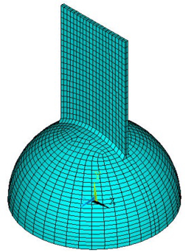
The static characteristics of the joint are essential for fatigue behavior.The WCPHSJs were statically analyzed by the software ANSYS to obtain the stress and deformation distributions on the hollow sphere under uniform tension loadings.KQ-4 as the typical specimen was chosen and analyzed, which has the following dimensions: a φ400 mm×10 mm welded hollow sphere, 2-160 mm×10 mm crossed plates, and the welded height hf of 8 mm.The material is Q235B.
The literature study[16] reveals that the crossed plate-half sphere can be used as the calculated model by assuming the fixed condition at the end of the sphere (see Fig.1(a)).Realizing that the interaction among the free ends of the four outstanding plates is relatively little, the above model may be simplified by considering only a single plate on a half sphere, the so-called single plate-half model (see Fig.1(b))[19].

(a)

(b)
Fig.1 Calculation model of the joints.(a)Cross plate; (b)Single plate
1.1 Foundation of FE model
In the FE analysis, the welding hollow sphere, cross plate, and the welding were assumed in the linear-elastic phase.The elastic modulus E of Q235B steel is 206 GPa and the Poisson ratio υ is 0.3.Linear elastic analyses were performed.The mapping division was adopted and the element type was SOLID95 (see Fig.2).The FE model consists of 1 970 elements and 12 811 nodes.The welding deficiency and residual stress caused by the joint welding process was ignored.The connection welding was considered based on the base metal material, but only the configuration size of the welding was considered.
(a)

(b)
Fig.2 The FE model.(a)Configuration model; (b)Connection of the plate and the sphere
1.2 The FEA results
The main task of the FE model for the specimen was to determine the location of the hot-spot and its stress condition.As such, the initial location of fatigue cracks can be determined.For the static linear-elastic analysis using the single plate-half model, the interaction effect between the cross plates was found to be negligible.Hence, for simplification, this model was adopted in the subsequent analyses.All analysis results were found to be reasonably accurate.Fatigue failure analysis for the specimens was not conducted.
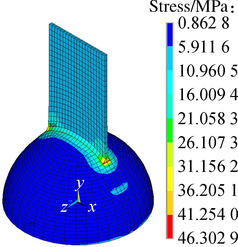
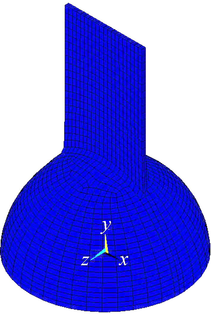
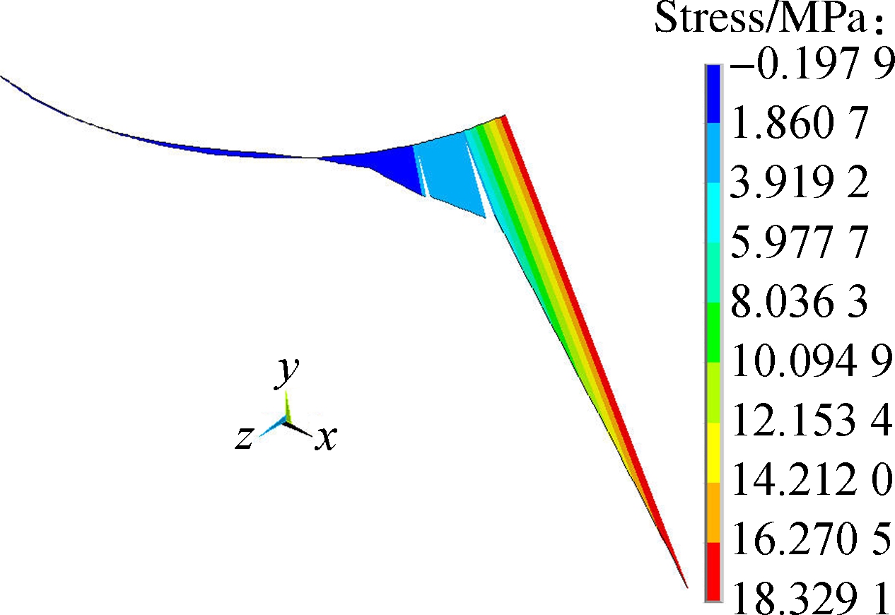
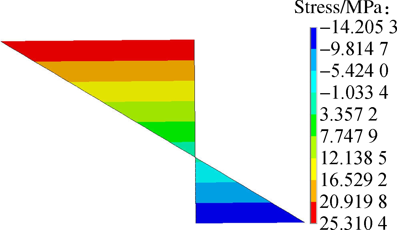
With the established FE model representing the joint, the stress and deformation distributions of the welded hollow sphere under uniform axial tension loading were obtained and analyzed (see Figs.3(a)and (b)).For the hot spot at the joint, the stress distribution along the radial, circumferential and the thickness directions of the hollow sphere were discussed in order to present the real stress state there (see Figs.3(c)to (e)).
1.3 Discussion of the analysis results
Figs.3(a)and (b)show that the Von-Mises stress and deformation at the free end of the connection between the crossed plate and welded hollow sphere are the greatest.
Figs.3(c)to (e)also show that:1)The normal stresses in the three directions (i.e., σθ,σφ,σR)at the hot spot are all greater than zero, indicating all tension and the worst stress condition; 2)The radial stress σθ decreases rapidly with the distance from the hot spot (the stress at 10 mm location being only 33.7% of that at the hot spot); 3)The circumferential stress σφ also decreases rapidly and is reversed at 28.6 mm location(σφmin≈10.5% of σφmax); 4)The stress along the sphere thickness σR reverses sign across the thickness with tensile stress prevailing over 64% of the thickness (σRmin≈36.0% of σRmax).
In conclusion, the weld toe location at the free end of the plate of a WCPHSJ is most critical, where fatigue failure will initiate.
2 Experimental Program
The main purpose of the fatigue tests is to develop the stress-loading cycle curves (i.e., S-N curves)for WCPHSJs.According to the Chinese standard[23], at least 14 sets of fatigue data are required to derive an S-N curve, in which about 8 sets will be used to develop the inclined portion of the curve and the remaining 6 sets will be used to achieve the horizontal part.Gurney[24] also reported that 8 to 12 similar specimens are needed to be tested to obtain the fatigue strength of a connection under random repeated loading conditions.EuroCode3[21] also specifies that a number of data points no less than 10 should be considered in the statistical analysis.
(a)
(b)

(c)
(d)
(e)
Fig.3 The FEA results.(a)The Von-Mises stress diagram; (b)The deformation diagram; (c)The radial stress distribution diagram; (d)The circumferential stress distribution diagram; (e)The stress distribution along the sphere thickness diagram
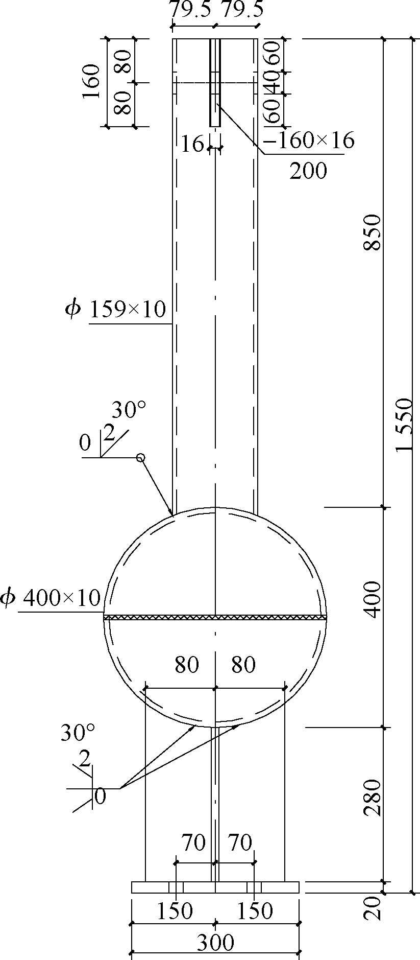
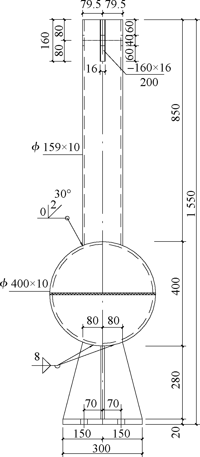
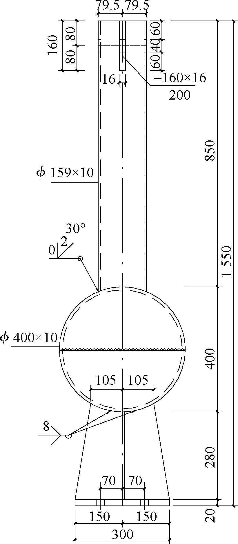
2.1 Specimen design
The conducted tests include five types of details designed to imitate the actual fatigue details of a grid structure with suspended cranes.They are labeled as KQ-4, KQ-5, KQ-6, KQ-7, and KQ-8, as shown in Fig.4.The fatigue design principle is that the load capacity of a WCPHSJ is less than that of welded circular tube-hollow sphere.Butt welds were used at either joint type for specimens KQ-4, KQ-5, and KQ-6, while fillet welds with the root height hf of 8 mm were used at either joint type for specimens KQ-7 and KQ-8 (see Tab.1).
The circular tube, welded hollow sphere, cross plate, and cover plate were fabricated from Q235B steel.The sphere meets the requirement of JG/T 11—2009[25] and all welded hollow sphere joints were not stiffened.

(a)

(b)
(c)
(d)
(e)
Fig.4 Fatigue details of the specimens (unit: mm).(a)KQ-4;(b)KQ-5;(c)KQ-6;(d)KQ-7;(e)KQ-8
Tab.1 Geometrical characteristics of the specimen
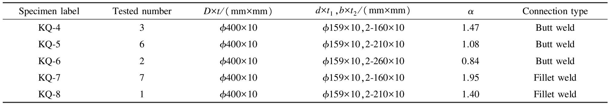
SpecimenlabelTestednumberD×t/(mm×mm)d×t1,b×t2/(mm×mm)αConnectiontypeKQ⁃43ϕ400×10ϕ159×10,2⁃160×101.47ButtweldKQ⁃56ϕ400×10ϕ159×10,2⁃210×101.08ButtweldKQ⁃62ϕ400×10ϕ159×10,2⁃260×100.84ButtweldKQ⁃77ϕ400×10ϕ159×10,2⁃160×101.95FilletweldKQ⁃81ϕ400×10ϕ159×10,2⁃210×101.40Filletweld
Notes:D is the diameter of the welded hollow sphere; t is the thickness of the sphere; d is the diameter of the steel tube; t1 is the thickness of the steel tube; b is the width of the crossed plate; t2 is the thickness of the crossed plate; α is the limit strength ratio of the steel tube welded sphere and the cross plate welded sphere.
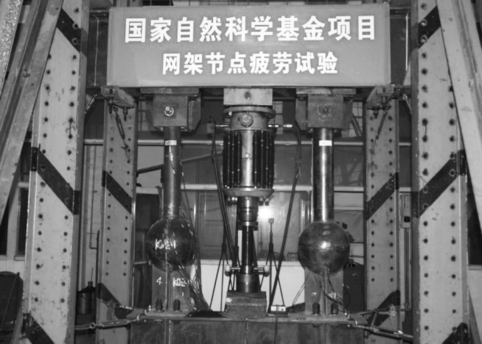
2.2 Test rig
The test rig (see Fig.5)is intended to test the specimens to study the fatigue behavior of WCPHSJs under the constant amplitude load.It was designed to be self-reacting and situated on the floor and the setup was relatively simple.Preliminary fatigue tests demonstrate that the test rig is efficient, stable, reliable, time saving, and cost effective.
(a)

(b)
Fig.5 Load program.(a)Central loading condition; (b)Bilateral loading condition
2.2.1 Load program
Two specimens were fixed on the steel beam in the test rig under the central loading condition (see Fig.5(a)), with its bottom connected with a pair of M33 high strength bolts and the top pinned to the rig by studs.The advantage of central loading is that the loads can be applied to two similar specimens at the same time.In addition, if one of the specimens fails in fatigue, then one of the following two alternatives may be considered: 1)Replace the damaged specimen with a new one and impose the load; 2)Apply a further increasing load to the undamaged specimen.The disadvantage of central loading is that the maximum load is limited to 50 t for each specimen as the fatigue machine can only accommodate 100 t of load capacity.
One specimen was fixed in the middle of the steel beam in the test rig under the bilateral loading condition (see Fig.5(b)), with its bottom connected by two pairs of M33 high strength bolts and its top also pinned to the rig by studs.The advantage of bilateral loading is that the maximum load stretches to 200 t, twice as large as the load capacity of the fatigue machine.
2.2.2 Test equipment
The Swiss made AMSLER fatigue test machine was used to simulate the constant amplitude fatigue loads on fatigue specimens during the test.The heaviest load was as high as 1 000 kN.The 1 000 kN hydraulic pressure servo fatigue machine was used to load the specimen at the frequency of 6.67 Hz.The loading cycle was represented by a strictly-controlled, smooth sine wave.
2.3 Fatigue test results and fatigue failure modes
2.3.1 Test results
Based on the test rig and pre-determined load program, five types of total 19 specimens were tested under various constant amplitude loads in ascending load order.The test results are summarized in Tab.2.
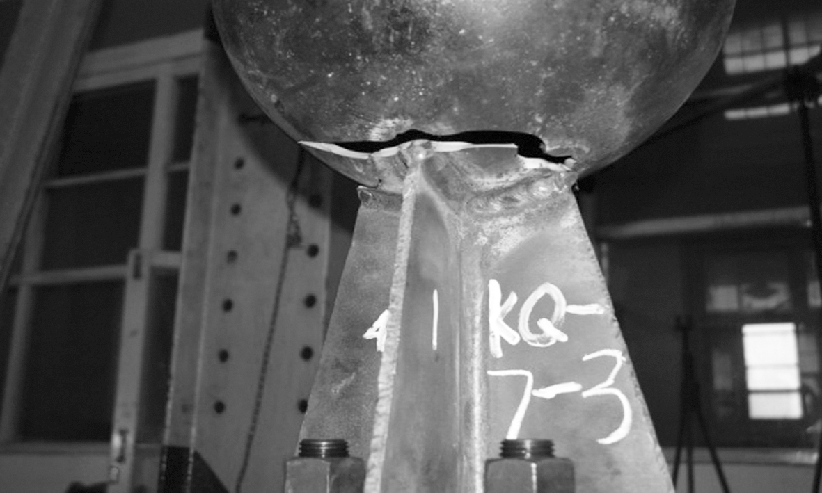
2.3.2 Fatigue failure modes
Based on the analysis of broken specimens, all 5 different specimen types appear to display a similar fatigue failure mode, namely the fatigue crack initiated on the edge of the weld toe at the joint between the cross plate and the sphere and then propagating circumferentially around the sphere with the diameter equaling the width of the entire cross plate.Typical failure modes of the specimens are shown in Fig.6.

(a)

(b)

(c)
(d)
Fig.6 Failure mode of fatigue specimens.(a)KQ-4-1;(b)KQ-5-13;(c)KQ-6-17; (d)KQ-7-3
2.3.3 Metallographic analysis of fatigue fracture
Metallographic analysis is a very important tool to detect material or a member fatigue fracture from the fracture form and presents some details of fatigue fracture.It can also provide important information of crack nucleation, crack initiation, crack propagation, and final fracture etc.An electron scanning microscope (TESCAN Mira3 LMH)was used to observe the precise fatigue fracture form and features.Through the constant amplitude fatigue tests on specimens KQ-4, KQ-5, KQ-6, KQ-7, and KQ-8, macroscopic and microscopic metallographic analyses were made to determine the fatigue fracture mechanism of WCPHSJs.
Tab.2 Test results of welded cross plate-hollow sphere joints under constant amplitude load
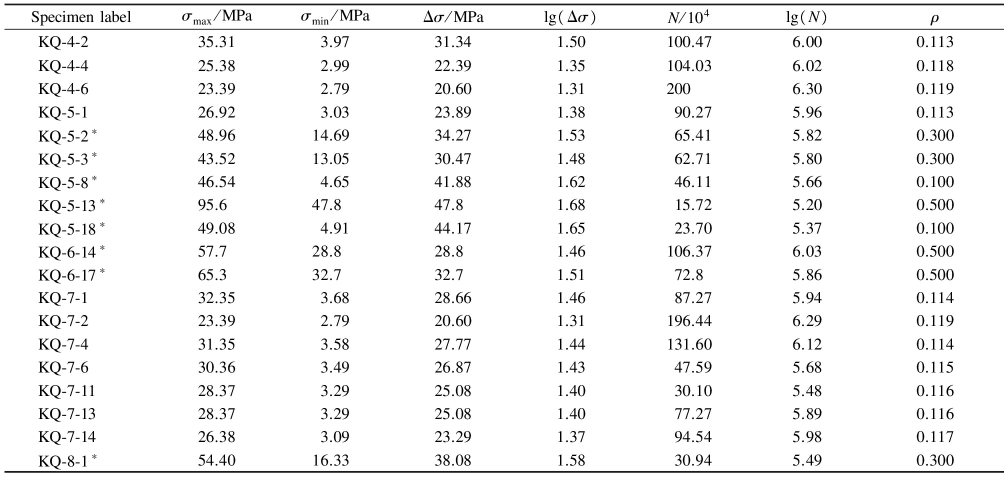
Specimenlabelσmax/MPaσmin/MPaΔσ/MPalg(Δσ)N/104lg(N)ρKQ⁃4⁃235.313.9731.341.50100.476.000.113KQ⁃4⁃425.382.9922.391.35104.036.020.118KQ⁃4⁃623.392.7920.601.312006.300.119KQ⁃5⁃126.923.0323.891.3890.275.960.113KQ⁃5⁃2∗48.9614.6934.271.5365.415.820.300KQ⁃5⁃3∗43.5213.0530.471.4862.715.800.300KQ⁃5⁃8∗46.544.6541.881.6246.115.660.100KQ⁃5⁃13∗95.647.847.81.6815.725.200.500KQ⁃5⁃18∗49.084.9144.171.6523.705.370.100KQ⁃6⁃14∗57.728.828.81.46106.376.030.500KQ⁃6⁃17∗65.332.732.71.5172.85.860.500KQ⁃7⁃132.353.6828.661.4687.275.940.114KQ⁃7⁃223.392.7920.601.31196.446.290.119KQ⁃7⁃431.353.5827.771.44131.606.120.114KQ⁃7⁃630.363.4926.871.4347.595.680.115KQ⁃7⁃1128.373.2925.081.4030.105.480.116KQ⁃7⁃1328.373.2925.081.4077.275.890.116KQ⁃7⁃1426.383.0923.291.3794.545.980.117KQ⁃8⁃1∗54.4016.3338.081.5830.945.490.300
Note: Specimens with * are subjected to the bilateral loading condition, and other specimens are subjected to the central loading condition; F is the axial load of fatigue specimens, kN; b is the width of crossed plate; t is the thickness of sphere; σ=F/πbt is the nominal stress of fatigue specimens; Δσ=σmax-σmin is the stress range; ρ=σmin/σmax is the stress ratio.
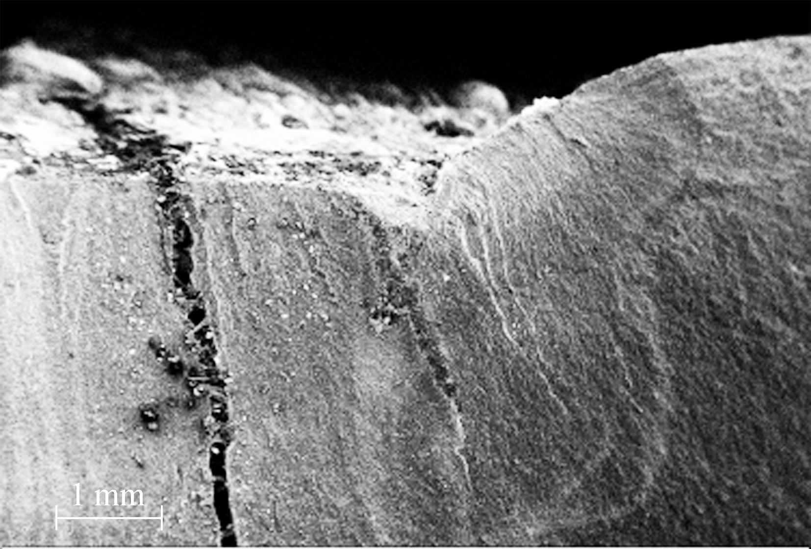
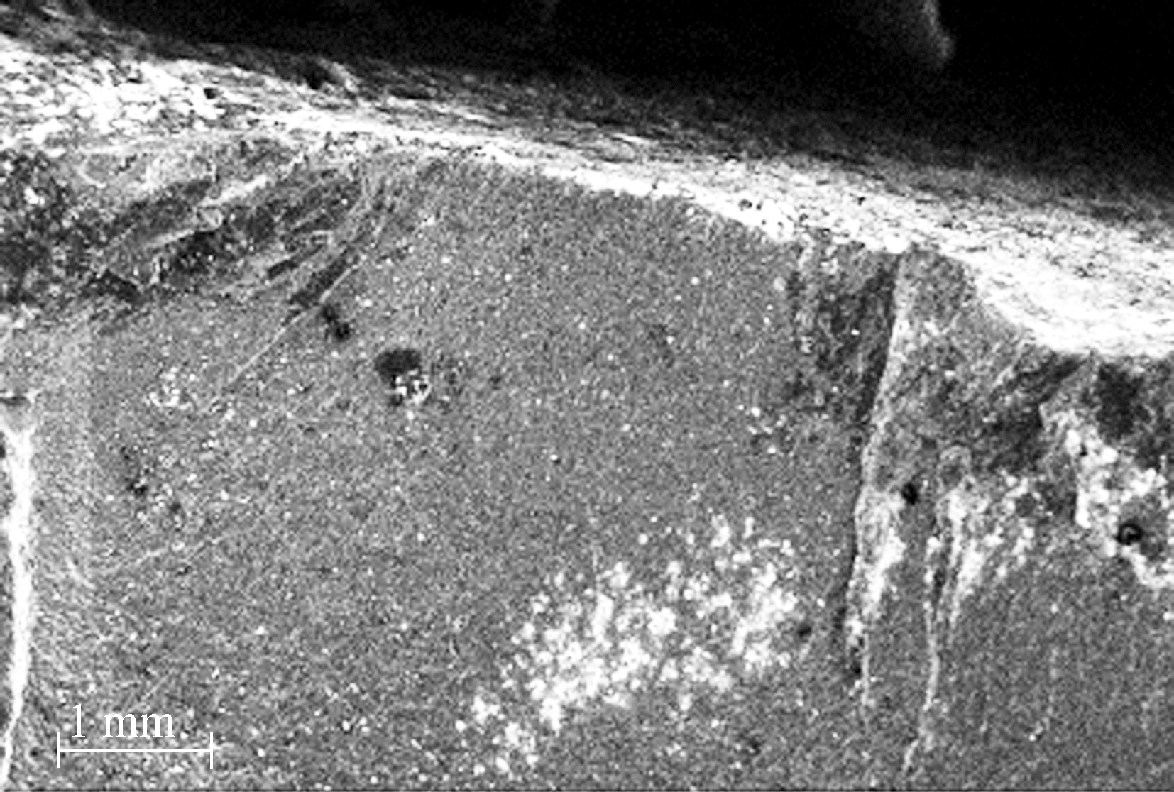
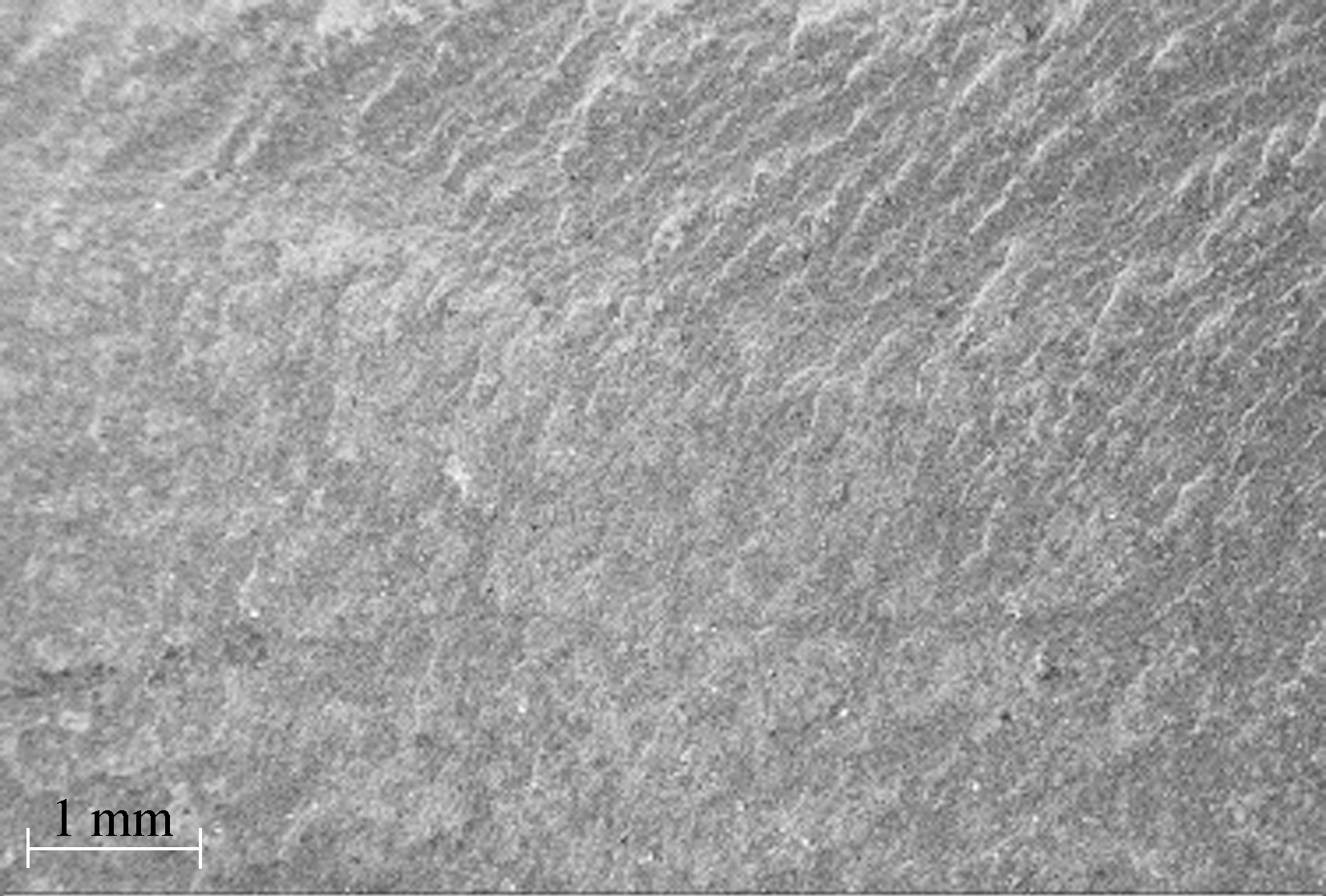
Some typical fatigue fractures surfaces for specimens KQ-7-4/6 are described as follows.Fig.7 show that the initial defects induced from manufacturing, pores and inclusions are the main source contributing to the fatigue problem.

(a)

(b)
Fig.7 Macro-fracture surface of fatigue specimen.(a)KQ-7-4; (b)KQ-7-6
Fig.7(a)also shows that the tiny vertical cracks in specimen KQ-7-4 lie in the sunken fracture zone where two bright blocks are noted.This implies that two fatigue sources exist in the fatigue fracture and both are in the initial stage of fatigue cracking.Each fatigue source propagates separately at first, then combines into a bigger crack source, and continues to propagate until broken.Fig.7(b)also shows the bright semi-circular region exists in the middle sunken fracture zone of specimen KQ-7-6.It has been determined as the fatigue source of the specimen.
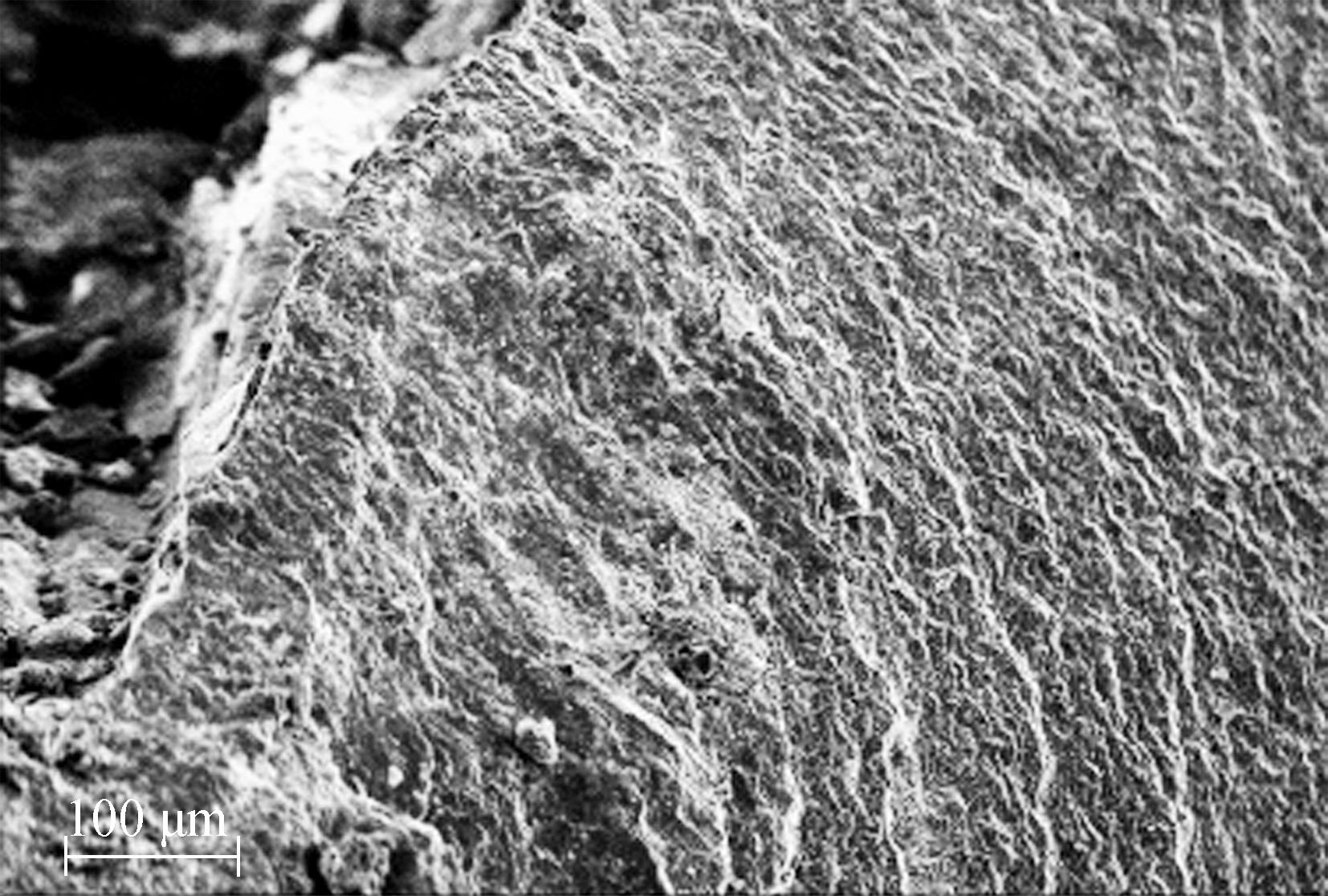
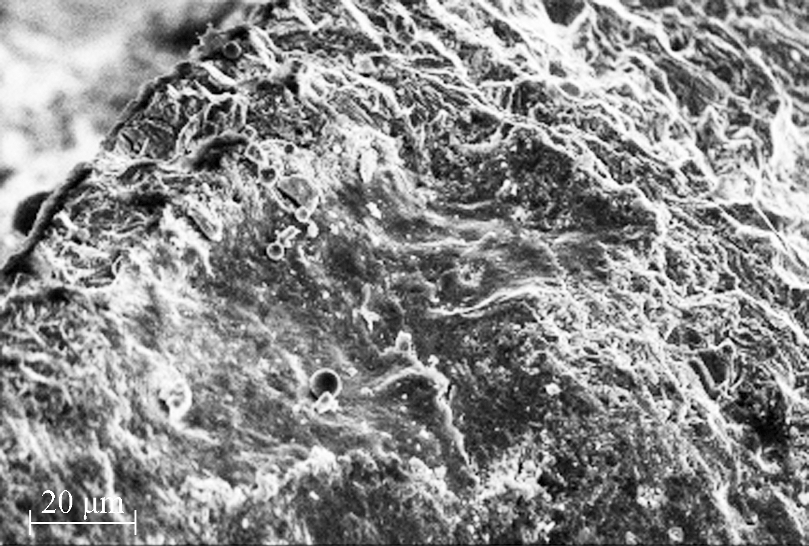
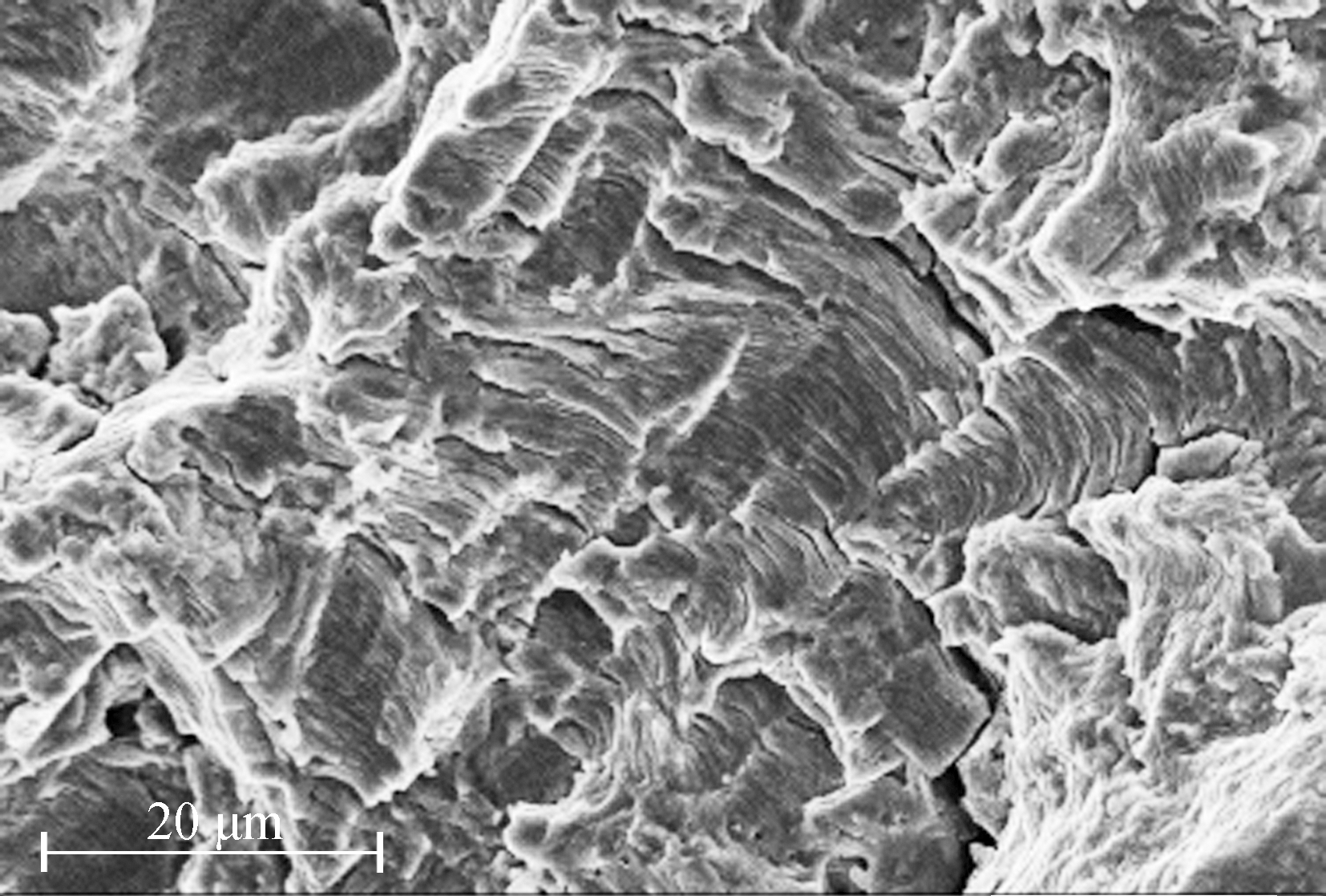
The two initial crack sourcesⅠ and Ⅱ in KQ-7-4 fatigue fracture were magnified 60 times (see Figs.8(a)and 9(a))to observe more clearly that some small voids exist in the middle region of fatigue sources.These initial defects detected were caused by the pores or inclusions during the test process, which led to fatigue source initiation.The first crack source magnified 2 000 times shows more clearly the propagated direction of the fatigue cracks (see Figs.8(b)and 9(b)).
The initial crack sources in KQ-7-6 fatigue fracture were magnified 60 times (see Fig.10(a))to observe more clearly that some small black voids exist in the bottom right region of fatigue sources and the developed fatigue zone is flat and smooth with radial shell-like lines.The initial defects found were due to the heat treatment during the test process.The crack source magnified 2 000 times (see Figs.10(b)and (c))shows more clearly that apparent fatigue source appears and tiny grain-size defects show up on the left side of the central region.In addition, Fig.10(c)also indicates that fatigue propagation is obvious and the interval of bay ridges becomes increasingly constant with the fatigue crack propagation after the initiation of the fatigue cracks.Fig.10(d)clearly shows each fatigue striation in the fatigue stripe in the fatigue propagation region that was magnified 5 000 times.
2.4 Constant amplitude fatigue design method
Nineteen effective fatigue test results listed in Tab.2 are taken to perform the regression analysis to obtain constant amplitude S-N curves of WCPHSJs in a grid structure, as shown in Fig.11, where Δσ is the stress constant amplitude and N is the number of loading cycles.
Based on the discrete fatigue test data shown in Fig.11, the following S-N equation is derived:
(a)
(b)
Fig.8 Micro-fracture surface of KQ-7-4(Ⅰ).(a)Magnified 60 times; (b)Magnified 2 000 times
(a)
(b)
Fig.9 Micro-fracture surface of KQ-7-4(Ⅱ).(a)Magnified 60 times; (b)Magnified 2 000 times

(a)

(b)
(c)
(d)
Fig.10 Micro-fracture surface of KQ-7-6.(a)Magnified 60 times; (b)Magnified 2 000 times (overall region); (c)Magnified 2 000 times (partial region); (d)Magnified 5 000 times
lgN=10.980 0-3.507 3lg(Δσ)±0.245 6
(1)
r=-0.763 3, [Δσ]2×106=18.38 MPa
(2)
where r is the correlation coefficient and [Δσ]2×10⁶ is the allowable maximum nominal stress amplitude corresponding to 2×10⁶ loading cycles.
The constant amplitude fatigue design method for WCPHSJs (Eq.(1))assumes Δσ as the design variable.The conventional fatigue design criterion can be described by

Fig.11 Constant amplitude S-N curves
Δσ≤[Δσ]
(3)
![]()
(4)
where Δσ=σmax-σmin, σmax is the maximum radial stress at the intersection of a joint and Δσh is the minimum radial stress; C and β are the two relevant coefficients, and their values are 0.955×10¹¹ and 3.507 3, respectively.
3 Fatigue Design Method Based on Hot-Spot Stress Amplitudes
To assess the fatigue strength of a WCPHSJ, the hot spot stress is more suitable than the nominal stress[16].Considering the complex configuration of the joint and taking the advantage of the conventional fatigue design, a fatigue design method using the hot spot stress amplitude as a design variable is feasible, which is capable of indicating the actual stress state in the fatigue crack resource.
3.1 Stress concentration factor kf at the hot spot location
A total of 25 finite element analyses (FEAs)were performed to analyze the WCPHSJs, which considered five parameters (sphere out-diameter, sphere thickness, cross plate width, cross plate thickness, and filled weld height), with each parameter varying 5 times.
In addition, a static test was conducted for one representative specimen to verify the FEA results[19].Both the FEA and test results indicate that the critical point or hot spot occurs at the weld toe of the free end intersection between the plate and sphere, and that the radial stress in the sphere at the hot spot location is very significant compared to the circumferential stress and the stress along the sphere thickness.This is in line with what has been reported[16].Based on the linear regression analysis, a kf formula for the plate end at the plate-sphere intersection may be derived.For the different specimens investigated, the kf values at the hot spots range from 3.176 to 5.365[19].
3.2 Fatigue design formula
Considering the stress distribution on the surface of a WCPHSJ, spherical radial stress at the weld toe at the end plate-sphere intersection was chosen as the main variable for the fatigue design method.For safer designs, the kf value of 3.176 is recommended to be multiplied to both sides of Eq.(3).The fatigue strength corresponding to N of 2×10⁶ cycles is viewed as an international unified standard, which yields the allowable hot-spot stress amplitude of 62.44 MPa.The following fatigue design formula is suggested:
Δσh=kfhΔσ≤[Δσh]2×10⁶
(5)
where Δσh is the hot spot stress amplitude and kfh is the stress concentration factor at the hot spot.
4 Conclusions
1)Fatigue failure is likely for welded cross plate-hollow sphere joints in a grid structure under repeated crane loads.Attention to the fatigue behavior of such suspension joints should be taken in design and erection.
2)Fatigue failure generally occurs at the weld toe location where severe stress is concentrated, as evidenced by the test and FEA results.For welded cross plate-hollow sphere joints, fatigue cracks initiate at the weld toe and then propagate circumferentially around the sphere with a diameter equivalent to the width of the cross plate until fatigue fracture.
3)The metallographic analysis shows that unavoidable initial welding defects caused by the surface processing may lead to a fatigue failure at the joint.
4)A better fatigue design method based on hot-spot stress amplitudes (Eq.(5))and the relevant S-N curves (Fig.11)for the welded cross plate-hollow sphere joints are suggested.
References
[1]Lei H G, Yin D Y.Research progress on fatigue of grid structure with suspension cranes [J].Spatial Structures, 2008, 14(4):32-36, 52.(in Chinese)
[2]Lei H G.The analysis on the surface stress of welded hollow sphere joint [J].Journal of Taiyuan University of Technology, 1994, 25(1):10-17.(in Chinese)
[3]Tan Y C, Lan T, Yang Y D, et al.Experimental investigation of the load-bearing behavior of hollow spherical joint for space truss and its rational design[C]//Selected Papers of Space Structure.Beijing, China: Chinese Science Publishing and Media Ltd., 1985:135-147.(in Chinese)
[4]Han Q H, Pan Y D, Liu X L.Analysis for the ultimate tensile and compressive bearing capacity of welded hollow spherical joints [J].China Civil Engineering Journal, 2003, 36(10):1-6.(in Chinese)
[5]Ministry of Housing and Urban-Rural Development of the People’s Republic of China.JGJ7—2010.Technical specification for space frame structures[S].Beijing: China Architecture and Building Press, 2010.(in Chinese)
[6]Han Q H, Liu X L.Ultimate bearing capacity of the welded hollow spherical joints in spatial reticulated structures [J].Engineering Structures, 2004, 26(1):73-82.DOI:10.1016/j.engstruct.2003.08.012.
[7]Dong S L, Xing L, Zhao Y, et al.Simplified theoretical solution and practical calculation method for welded hollow spherical joints of rectangular hollow section members [J].China Civil Engineering Journal, 2006, 39(6):12-18.(in Chinese)
[8]Hu W S, Huang P, Hu H B.Study on the bearing capacity formula of welded hollow spheres in space trusses [J].Building Science, 1995, 3:39-42.(in Chinese)
[9]Wang X L, Luan W.Ultimate bearing capacity of large-scale welded hollow spherical joint in tests [J].Spatial Structures, 2011,17(3):42-46.(in Chinese)
[10]Jiang L C, Gao R, Xu G B.Study on influence of different factors on support capacity of hollow spherical connectors [J].Journal of Northern Jiaotong University, 1998, 22(4):41-44.(in Chinese)
[11]Xiong S S, Ji H, Deng J, et al.Finite element analysis and full-scale experimental research of complex loading on large-diameter welded hollow spherical joint [J].Engineering Mechanics,2006,23(Sup I):184-188.(in Chinese)
[12]Ji H, Xiong S S, Huang L T.Finite element analysis and full-scale experimental study on large spherical joint in multi-axial loading [J].Engineering Mechanics, 2010,27(4):173-178.(in Chinese)
[13]Ding Y, Qi L, Li Z X.Mechanical calculation model for welded hollow spherical joint in spatial latticed structures [J].Advanced Steel Construction, 2011, 7(4):330-343.
[14]Zhang Z Y, Hao S W.Nonlinear numerical analysis on the existing welded hollow spherical joints strengthened by rib stiffeners outside the ball [J].Building Science, 2012, 28(9): 14-19.(in Chinese)
[15]Chen Y, Guan S J, Guo Y, et al.Study on ultimate tensile bearing capacity of welded hollow spherical joints with stiffeners and a diameter of over 1m [J].China Civil Engineering Journal, 2016, 49(2):1-10.(in Chinese)
[16] Xiao Y K, Qin D Q, Ma Q R.The stress analysis of crossed plate-sphere joints under tensile loadings [J].Journal of Taiyuan University of Technology, 1992, 23(2):45-52.(in Chinese)
[17]Xu G B, Cui J.Fatigue of space trussed and its fatigue life calculation [J].Journal of Building Structures,1994, 15(2):25-34.(in Chinese)
[18]Zhang Y L, Pan J Y, Pan J L.Analysis of common fatigue details in steel truss structures [J].Tsinghua Science and Technology, 2004, 9(5):583-588.
[19]Jiao J F.The theoretical and experimental research on fatigue performance of crossed plate welded hollow spherical connection in plate-type grid structure [D].Taiyuan: College of Architecture and Civil Engineering, Taiyuan University of Technology, 2013.(in Chinese)
[20]Liu Y J, He C, Huang C X, et al.Very long life fatigue behaviors of 16Mn steel and welded joint[J].Structural Engineering and Mechanics.2014, 52(5):889-901.
[21]CEN.Eurocode3 Design of steel structures—Part 1.9: Fatigue[S].European Committee for Standardization,2005.
[22]Ministry of Housing and Urban-Rural Development of the People’s Republic of China.GB 50017—2003.Code design of steel structures[S].Beijing: China Architecture and Building Press, 2003.(in Chinese)
[23]General Administration of Quality Supervision, Inspection and Quarantine of the People’s Republic of China.GB/T 13682—92.Axial load fatigue testing for threaded fasteners[S].Beijing: China Standard Press, 1992.(in Chinese)
[24]Gurney T R.Fatigue of welded structures [M].2nd ed.London, UK: The Welding Institute Cambridge University Press, 1979.
[25]Ministry of Housing and Urban-Rural Development of the People’s Republic of China.JG/T 11—2009.Welded hollow spherical node of space grid structures[S].Beijing: China Standard Press, 2009.(in Chinese)