Steel bridges are widely used in bridge construction based on their large span, easy transportation and convenient installation[1].However, distress such as cracking, potholes, debonding and rutting often occur in the deck pavement during their use[2-4].In an attempt to clarify the cause and the type of distress occurring, a large number of analyses have been carried out on steel deck pavement distress[5-8].To prevent distress, the finite element numerical simulation method is often used to solve the mechanical response of the steel deck pavement and to determine the design index of tensile stress and shear stress.However, while distress tends to be more serious on sections with a large longitudinal slope, only a few studies have been done on the large longitudinal slope steel deck pavement and there are currently no design requirements in China.Therefore, analyzing the influence of the longitudinal slope on the mechanical response of the pavement is necessary to guarantee the endurance of the steel deck pavement.
In this study, a method of slope-modulus transformation was proposed for the mechanical analysis of the steel deck pavement based on the time-temperature equivalence principle[9].Next, a three-dimensional solid-shell finite element model was established considering the mechanical action on the slope.The model was then verified as reliable by comparing the results to the current state-of-the-art methods.Thirdly, the critical load position of tensile stress and shear stress of the steel deck pavement was determined by measuring different load positions in the model.Finally, the influence of the longitudinal slope on the mechanical response of the steel deck pavement under uniform speed and emergency braking was analyzed to provide a reference for the design of large longitudinal slope steel deck pavements.
1 Time-Temperature Equivalence Conversion
1.1 Basic principles
The time-temperature equivalency principle demonstrates the equivalence of rising temperatures and extending action time on the viscoelastic behavior of polymers[9].Asphalt is a viscoelastic material; thus, it has an equivalency in its time and temperature effect.As a vehicle drives up a slope, the speed of the vehicle will be reduced and the load period will be improved accordingly.Furthermore, based on the time-temperature equivalency principle, the increase in load period can also be regarded as the increase in the material temperature.
1.2 Slope-modulus transformation
1.2.1 Slope-speed of vehicle
As a vehicle drives along an increasing longitudinal slope, the vehicle’s horizontal force component increases gradually, whereas the driver’s longitudinal sight decreases gradually.Thus, the speed of the vehicle should be reduced to ensure driving safety[10].Furthermore, at a longitudinal slope of 3% or more, the speed of the vehicle should be decreased directly with the increasing longitudinal slope.According to the national standard of China, the maximum longitudinal slope for safe driving is 9%[11].Taking into account the work done by Zhou[10] and Yan[12] on the influence of longitudinal slope on the speed of vehicle and considering the driving characteristics of the steel deck pavement, the maximum safe driving speed of vehicle v corresponding to an increasing longitudinal slope is shown in Tab.1[10,12].Here, 60 km/h is used as a reference speed.
Tab.1 Maximum safe driving vehicle speed corresponding to longitudinal slope
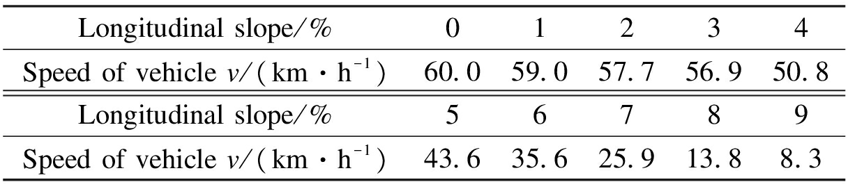
Longitudinalslope/%01234Speedofvehiclev/(km·h-1)60 059 057 756 950 8Longitudinalslope/%56789Speedofvehiclev/(km·h-1)43 635 625 913 88 3
1.2.2 Slope-load period
The load period of repeated loads t can be calculated as[13]

(1)
where L is the running distance, m; N is the action times of loading; P is the axle load of vehicle, kN; nw is the number of wheels on an axle; p is the tire pressure, MPa; and B is the contact width between the wheel and pavement, cm.
Taking N as 5×10⁵, P as 140 kN, p as 0.7 MPa, nw as 4,B as 20 cm, and v as specified in Tab.1, the load period corresponding to the longitudinal slope is shown in Tab.2[13].
Tab.2 Load period of 5×10⁵ times corresponding to longitudinal slope

Longitudinalslope/%01234Loadperiodt/s75007621780279108855Longitudinalslope/%56789Loadperiodt/s1032112655173883272754087
1.2.3 Slope-equivalent temperature
According to the Williams-Landel-Ferry equation (WLF), assuming that the temperature at zero longitudinal slope is 23 ℃, the time-temperature conversion formula of asphalt can be simplified as [14-15]
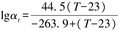
(2)
where αt is the shift factor, αt=t0/t, and t0 is the load period of 0 longitudinal slope, s; and T is the temperature at time t.
Thus, the temperature corresponding to the increasing longitudinal slope based on the time-temperature equivalency principle is shown in Tab.3.
Tab.3 Equivalent temperature corresponding to longitudinal slope

Longitudinalslope/%01234EquivalenttemperatureT/℃232323 123 123 4Longitudinalslope/%56789EquivalenttemperatureT/℃23 824 325 126 728 0
1.2.4 Slope-equivalent modulus
The modulus-temperature correction formula of asphalt based on FWD is[16]

(3)
where K is the modulus-temperature correction factor; ET0 and ET are modulus at T0 and T, MPa; and T0 is the reference temperature, 23 ℃.
An asphalt deck pavement is composed of an upper layer of stone mastic asphalt(SMA)and a lower layer of epoxy asphalt(EA).When the longitudinal slope is zero, the SMA modulus is 1 400 MPa and the EA modulus is 2 600 MPa.Research has shown that the time-temperature transformation of SMA, EA and dense-graded asphalt concrete (AC)is similar between 20 and 40 ℃[17-18].Thus, Eqs.(2)and (3)based on AC experimental data are suitable for SMA and EA.The equivalent modulus of the two deck component layers corresponding to the longitudinal slope is shown in Tab.4.
Tab.4 Equivalent modulus corresponding to longitudinal slope
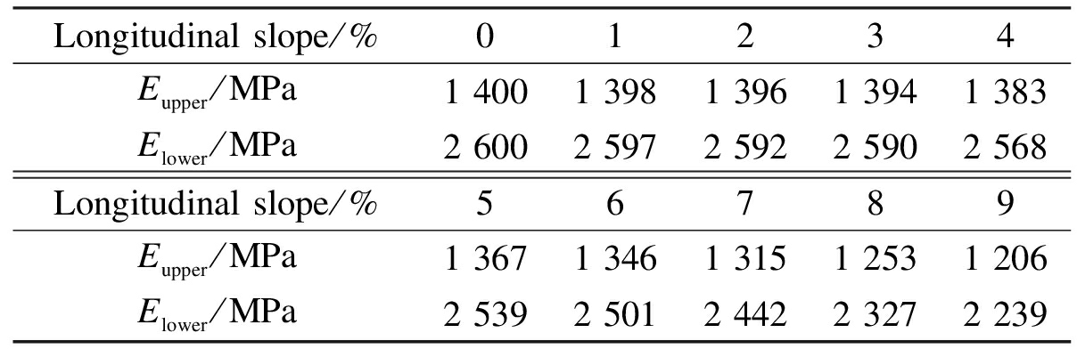
Longitudinalslope/%01234Eupper/MPa14001398139613941383Elower/MPa26002597259225902568Longitudinalslope/%56789Eupper/MPa13671346131512531206Elower/MPa25392501244223272239
2 Mechanical Action on Slope
When a vehicle is driving along a high longitudinal slope, the deck pavement is subjected to a vertical load due to the pressure from the vehicle weight, as well as a horizontal load comprised of the driving force and the driving resistance counterforce.This is depicted in Fig.1.Here, the vertical load Pv, the horizontal load under uniform speed Fr, and the horizontal load under emergency braking Fs can be calculated as

(4)
where G is the vehicle gravity, kN; Gv is the vertical force of vehicle gravity, kN; α is the gradient of the longitudinal slope; f is the coefficient of rolling friction, 0.02 for asphalt; and φ is the coefficient of the sliding friction, 0.5 for asphalt.Values of Pv, Fr, and Fs corresponding to the increasing longitudinal slope are shown in Tab.5.
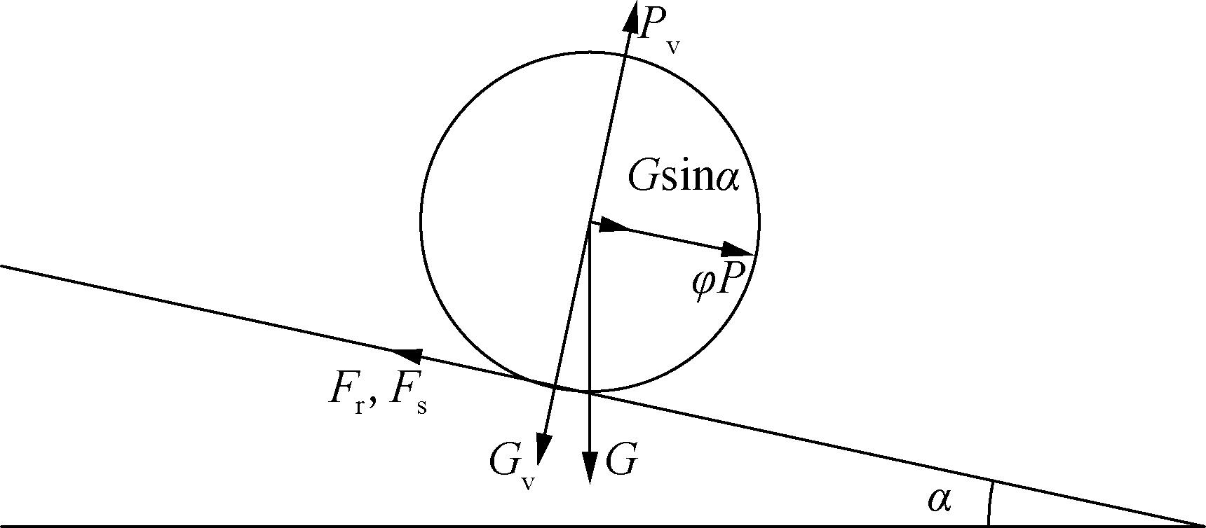
Fig.1 Mechanical action on longitudinal slope
Tab.5 Mechanical action corresponding to longitudinal slope
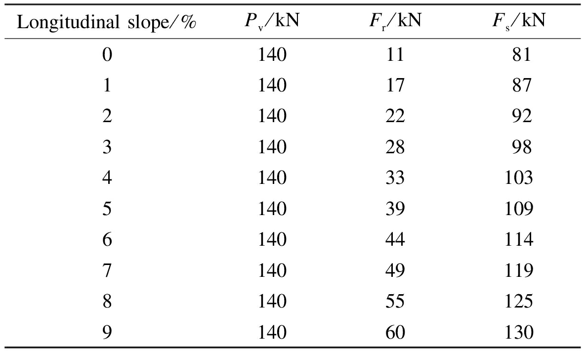
Longitudinalslope/%Pv/kNFr/kNFs/kN01401181114017872140229231402898414033103514039109614044114714049119814055125914060130
3 Mechanical Model of Deck Pavement
3.1 Basic assumptions
1)The orthotropic steel deck pavement system is an integrated system of homogeneous, continuous and isotropic elastic materials.
2)The pavement and steel deck are completely continuous.The bonding layer is not considered separately.
3)The shift and deformation of the orthotropic steel deck are small in comparison to the steel deck thickness and thus can be omitted from the calculations here.
3.2 Load of vehicle
To simulate the mechanical response of a steel deck pavement under a heavy load, a 140 kN single-axle double-wheel load is used in this study, which is consistent with the national standard of China[19].Each set of double-wheels is assumed to weigh 70 kN.The vehicle load is uniformly distributed on the surface of the deck pavement with a rectangular contact area of 25 cm in length and 50 cm in width overall, as shown in Fig.2[19].Thus, when the longitudinal slope is 6%, the contact area sustains a vertical load of 0.7 MPa and a horizontal load of 0.22 MPa through Eq.(4).
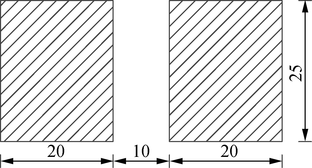
Fig.2 Load area in finite element model(unit: cm)
3.3 Model parameters and boundary condition
The modeled steel deck and pavement were 4.2 m in transverse direction and 6.0 m in longitudinal direction and contained four diaphragms and seven U-ribs(trapezoidal stiffeners).The diaphragms were 4.2 m in transverse direction and 0.012 m in longitudinal direction.The longitudinal slope was defined as 6%.Remaining structural parameters used in the model are defined in Tab.6 and Tab 7.Vertical displacement on the deck and pavement was allowed, whereas horizontal displacement was prohibited.The bottom of the diaphragm was fully consolidated[20].
Tab.6 Geometric size of the finite element model mm

ThicknessofSMAlayerh1ThicknessofEAlayerh2Thicknessofbridgedeckh3OpeningwidthofU⁃ribbHeightofU⁃ribHThicknessofU⁃ribh4SpacingofU⁃ribLUSpacingofdiaphragml40301630026086002000
Tab.7 Material parameters of the finite element model

ElasticmodulusofSMAlayer/MPaPoissonratioofSMAlayerElasticmodulusofEAlayer/MPaPoissonratioofEAlayerElasticmodulusofsteelplate/GPaPoissonratioofsteelplate14000 2526000 252100 3
3.4 Unit selection and mesh generation
Asphalt pavement was meshed into 8-node linear hexahedron reduced integral units, C3D8R.The steel box grinders were meshed into 4-node membrane strain reduction integral units, S4R.The generated mesh finite element model is shown in Fig.3.
3.5 Load position
Considering the effects of the diaphragms and ribs, the load position in transverse direction was divided into three cases as shown in Fig.4(a).Position 1 indicates that the double-wheel load was on the center of a U-rib, Position 2 indicates that the double-wheel load was on the top of a U-rib, and Position 3 indicates that the double-wheel load was located centrally between two U-ribs.The distance between the load and the diaphragm was divided into five cases: The top of the diaphragm (0 m), 1/8 span (0.25 m), 1/4 span (0.5 m), 3/4 span (0.75 m), and 1/2 span (1 m), as shown in Fig.4(b).
3.6 Model verification
The maximum transverse tensile strain of the steel deck pavement is defined as[21]

(a)

(b)
Fig.3 Mesh generation of asphalt pavement and steel box girder.(a)Asphalt pavement; (b)Steel box girder

(a)
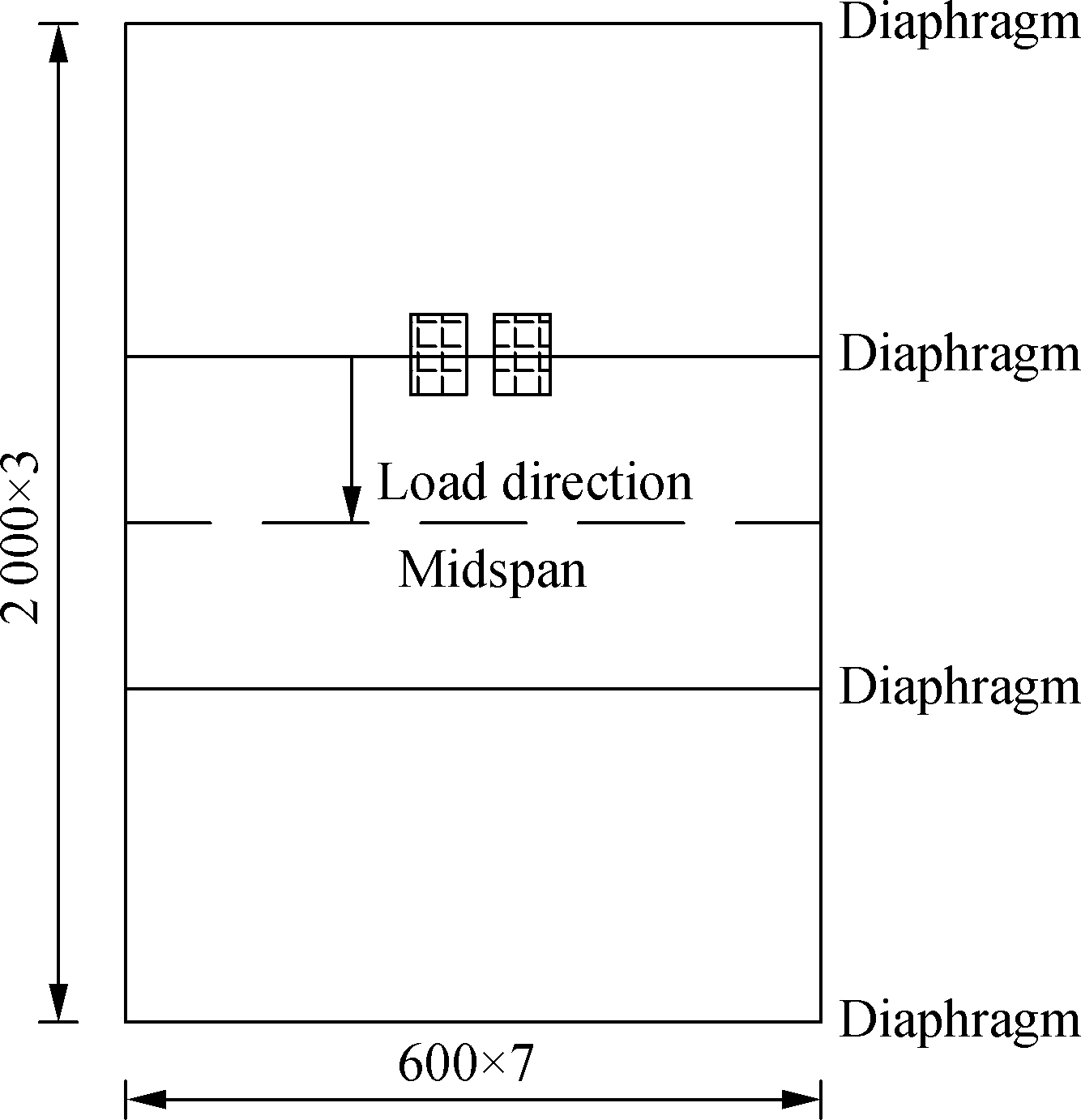
(b)
Fig.4 Load position in transverse and longitudinal direction.(a)In transverse direction; (b)In longitudinal direction(unit: mm)
(εx)max=k1k2k3k4k5k6k7εx0
(5)
where εx0 is the maximum transverse tensile strain at the critical transverse load position of the steel deck pavement, taking a value of 6.4×10⁻⁴[10];k1 is the correction factor of longitudinal load position and is equal to 1.54; k2 is the correction factor of the bridge deck depth, k2=0.001 8 h3-1.332 4/εx0; k3 is the correction factor of diaphragm spacing, k3=(37.076l2-334l+1 326.6)/εx0; k4 is the correction factor of U-rib opening width, k4=(-5 533.8b2+8 180.3b-1 316)/εx0; k5 is the correction factor of pavement modulus, k5=151 619 E-0.797 8/εx0, where E is the pavement modulus; k6 is the correction factor of pavement depth, k6=5.338 6h-1.569 3/εx0, where h is the pavement depth in m; and k7 is the correction factor of axle load, k7=P1/P0, where P1 is the designed axle load in kN and P0 is the reference axle load of 130 kN.
The finite element simulation was then performed with the critical load position of transverse tensile strain[21].Comparing the results of the formula with the developed finite element model, it can be seen in Fig.5 that the maximum transverse tensile strains calculated are comparable under increasing load.Thus, the developed finite element model is deemed reliable.

Fig.5 Comparison of the developed finite element model to the accepted formula of the maximum transverse tensile strain
4 Stress Analysis of Deck Pavement
4.1 The critical load position
The maximum pavement stress at different load positions is shown in Fig.6 and Fig.7.
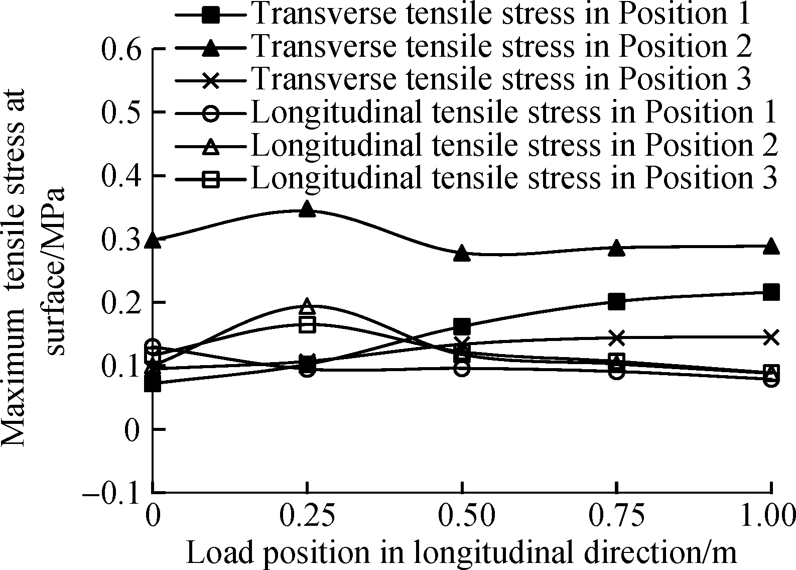
Fig.6 The relationship between maximum tensile stress and load position
As shown in Fig.6, the critical load position of transverse and longitudinal tensile stress at the pavement surface occurs at Position 2 and 1/8 span.The maximum transverse tensile stress at the pavement surface occurs directly underneath the double-wheel load area, as shown in Fig.8.
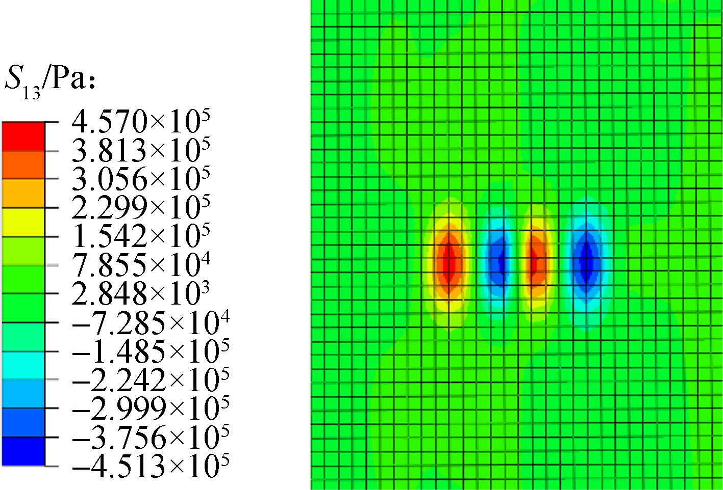
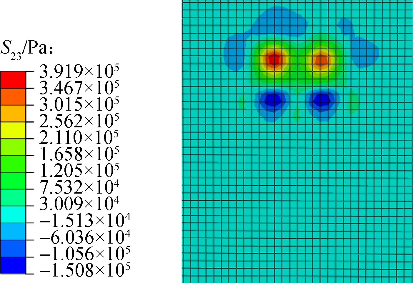
The critical load position of transverse shear stress between the pavement and the deck occurs at Position 2 and 1/2 span, whereas the critical load position of longitudinal shear stress occurs at Position 2 and 1/8 span, as shown in Fig.7.The position of maximum transverse shear stress at the pavement bottom occurs at the outer edge of the double-wheeled load, as shown in Fig.9(a).The position of maximum longitudinal shear stress at the pavement bottom occurs on the backedge of the double-wheeled load, as shown in Fig.9(b).
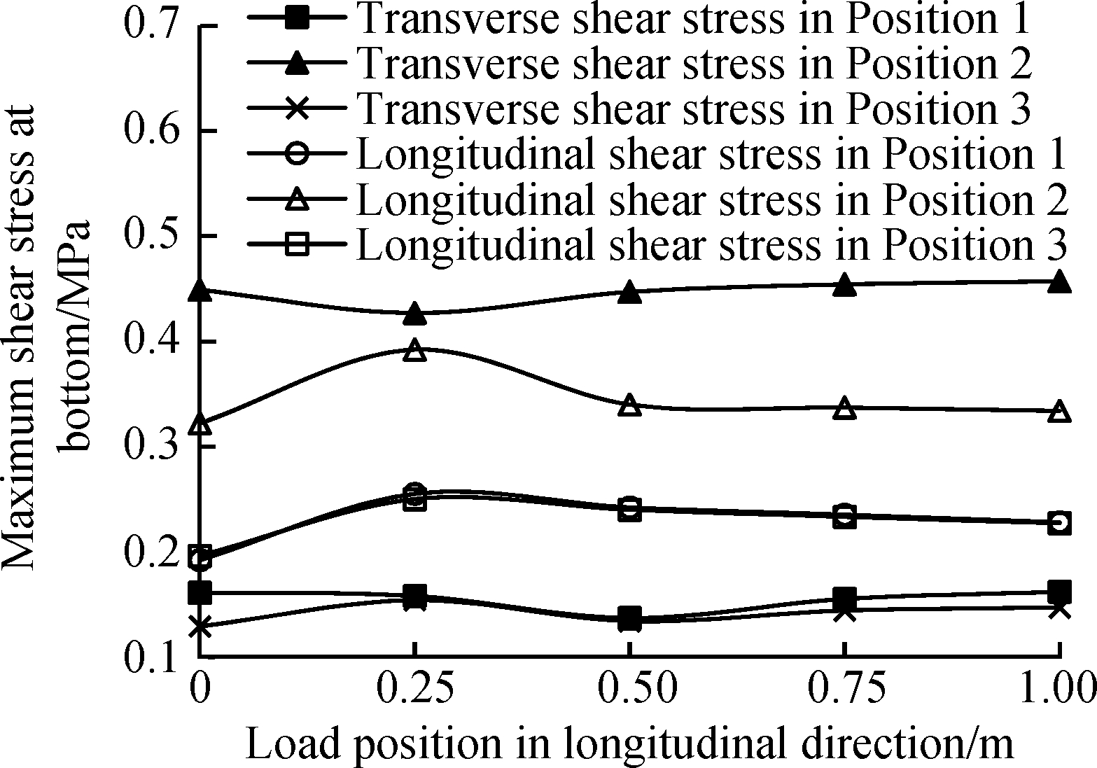
Fig.7 The relationship between maximum shear stress and load position
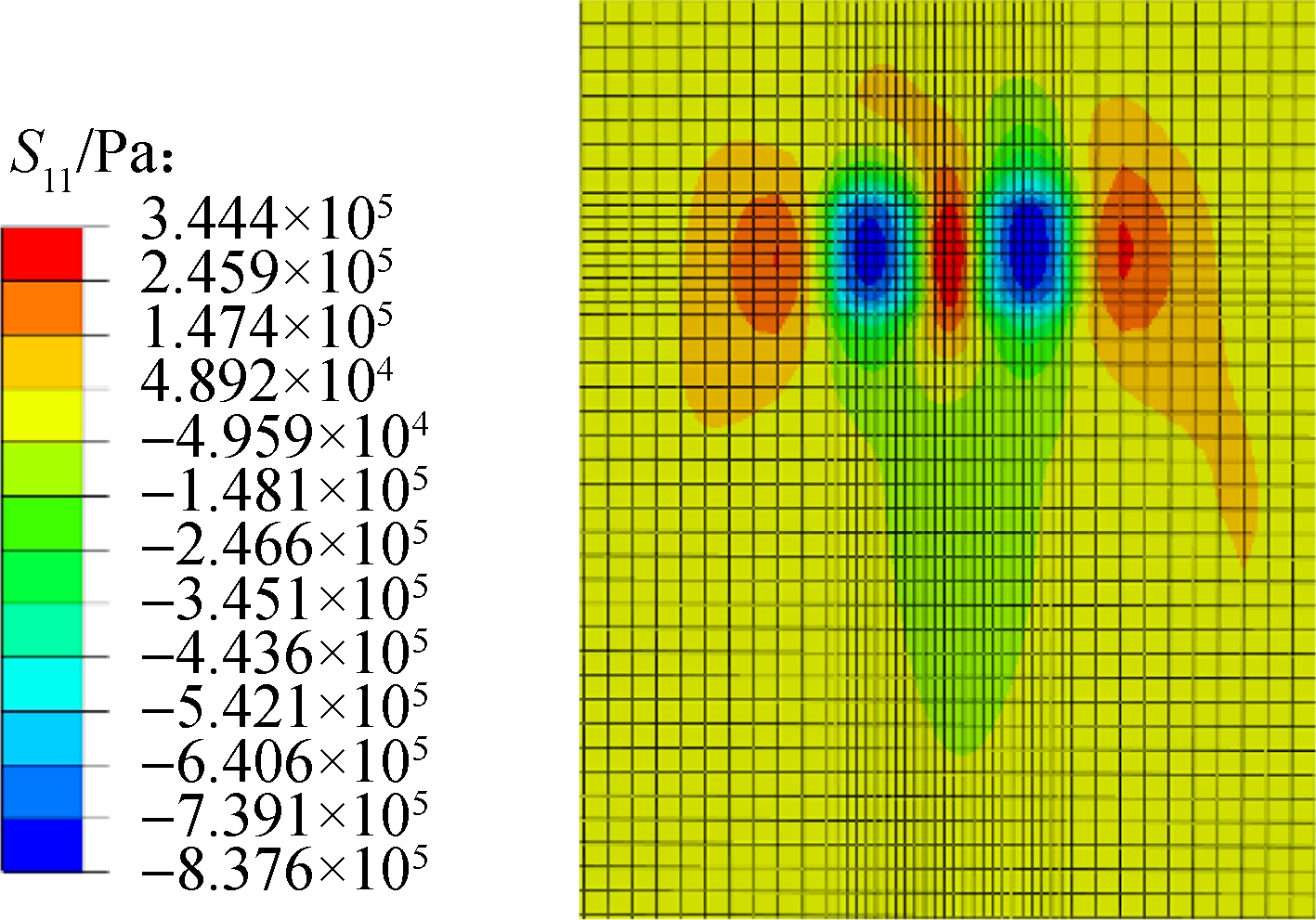
Fig.8 Maximum transverse tensile stress at surface
(a)
(b)
Fig.9 Maximum shear stress at bottom.(a)Transverse shear stress; (b)Longitudinal shear stress
4.2 Under uniform speed
The longitudinal slope range used in this study ranged from 0% to 9% while the other parameters remained unchanged in the simulation.Time-temperature equivalence and the influence of longitudinal slope on horizontal force of the steel deck pavement were considered.The results from this trial are shown in Tab.8.
Tab.8 Mechanical response under uniform speed
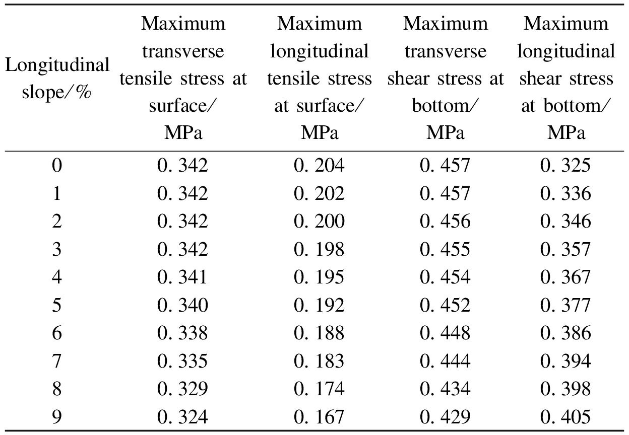
Longitudinalslope/%Maximumtransversetensilestressatsurface/MPaMaximumlongitudinaltensilestressatsurface/MPaMaximumtransverseshearstressatbottom/MPaMaximumlongitudinalshearstressatbottom/MPa00 3420 2040 4570 32510 3420 2020 4570 33620 3420 2000 4560 34630 3420 1980 4550 35740 3410 1950 4540 36750 3400 1920 4520 37760 3380 1880 4480 38670 3350 1830 4440 39480 3290 1740 4340 39890 3240 1670 4290 405
From the results presented in Tab.8, the following conclusions regarding the effect of longitudinal slope under uniform speed can be drawn:
1)Increased longitudinal slope has no significant effect on the maximum transverse tensile stress at the pavement surface.However, increased longitudinal slope does have some effects on the maximum longitudinal tensile stress.The maximum transverse tensile stress at the pavement surface is always greater than the maximum longitudinal tensile stress.
2)Increased longitudinal slope also has no significant effect on the maximum transverse shear stress at the pavement bottom.However, the longitudinal slope does have a significant effect on the maximum longitudinal shear stress.The maximum transverse shear stress at the pavement bottom is always greater than the maximum longitudinal shear stress.
4.3 Under emergency braking
The mechanical response of the deck pavement under emergency braking is shown in Tab.9.
From the results presented in Tab.9, the following conclusions regarding the effect of the longitudinal slope under emergency braking can be drawn:
1)Increased longitudinal slope has no significant effect on the maximum transverse tensile stress at the pavement surface.However, increased longitudinal slope has a significant effect on the maximum longitudinal tensile stress.The maximum longitudinal tensile stress at the pavement surface increases rapidly with the increase of longitudinal slope.The maximum longitudinal tensile stress at the pavement surface is greater than the maximum transverse tensile stress when the slope is equal to the critical slope gradient of maximum transverse and longitudinal tensile stress of 6%.
Tab.9 Mechanical responseunder emergency braking
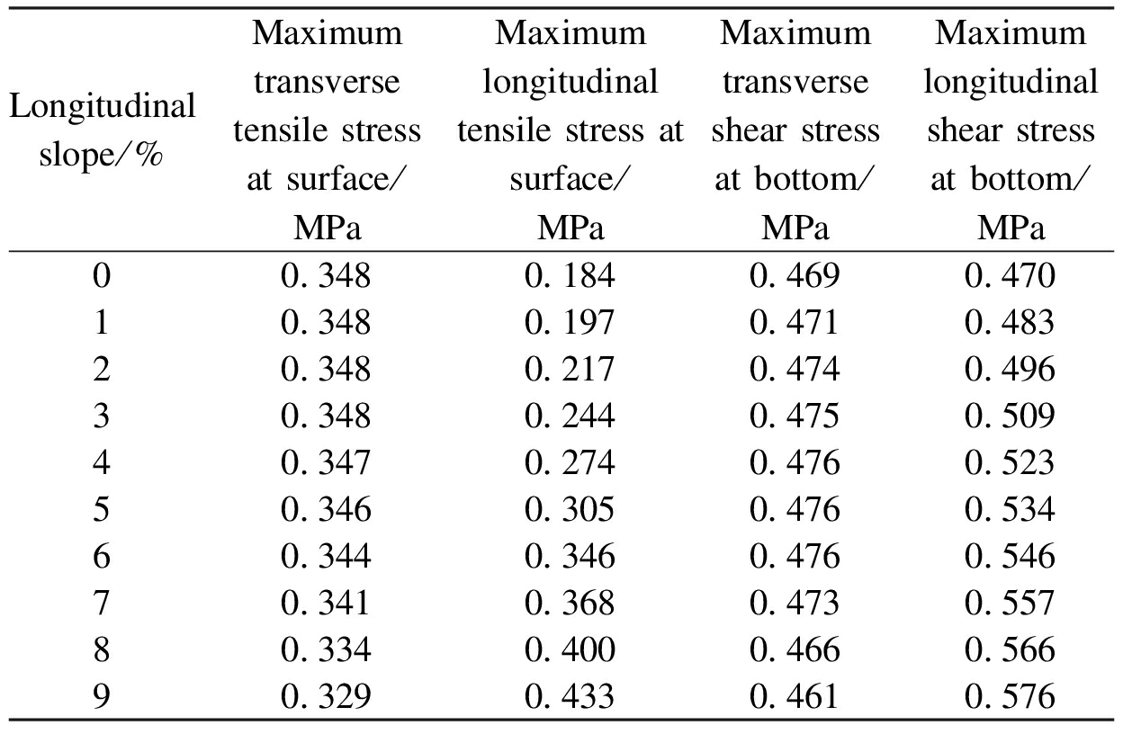
Longitudinalslope/%Maximumtransversetensilestressatsurface/MPaMaximumlongitudinaltensilestressatsurface/MPaMaximumtransverseshearstressatbottom/MPaMaximumlongitudinalshearstressatbottom/MPa00 3480 1840 4690 47010 3480 1970 4710 48320 3480 2170 4740 49630 3480 2440 4750 50940 3470 2740 4760 52350 3460 3050 4760 53460 3440 3460 4760 54670 3410 3680 4730 55780 3340 4000 4660 56690 3290 4330 4610 576
2)Increased longitudinal slope also has no significant effect on the maximum transverse shear stress at the pavement bottom.However, increased longitudinal slope has a significant effect on the maximum longitudinal shear stress.The maximum longitudinal shear stress at the pavement bottom increases gradually with the increase of longitudinal slope.The maximum longitudinal shear stress at the pavement bottom is always greater than the maximum transverse shear stress.Thus, the maximum longitudinal shear stress should be taken as the design index of shear stress during the shear resistance design.
4.4 Comparison of two situations
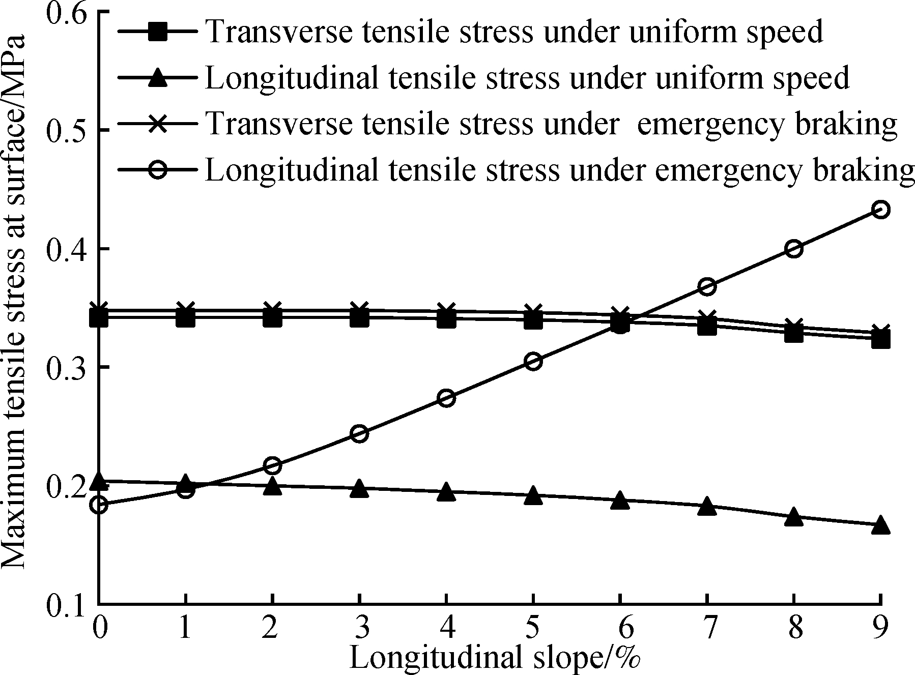
A comparison of stress analysis performed under uniform speed and emergency braking is shown in Fig.10.
From Fig.10, it can be seen that the maximum transverse tensile stress at the pavement surface and the maximum transverse shear stress at the pavement bottom under uniform speed are nearly equal to those of the emergency braking.However, under emergency braking, the maximum longitudinal tensile stress at the pavement surface and the maximum longitudinal shear stress at the pavement bottom cause great change with the increase of longitudinal slope, which should be focused on in design.
5 Conclusions
1)The influence of the longitudinal slope should be considered in the design of large longitudinal slope steel deck pavements.
2)The critical load positions of the transverse and longitudinal tensile stress of the steel deck pavement at the surface are located at the top of each U-rib in the transverse direction and 1/8 span in the longitudinal direction.
3)The critical load position of transverse shear stress on the steel deck pavement between the deck and the pavement is located at the top of each U-rib in the transverse direction and 1/2 span in the longitudinal direction.The critical load position of longitudinal shear stress is located at the top of each U-rib in the transverse direction and 1/8 span in the longitudinal direction.
(a)

(b)
Fig.10 Comparisons of maximum tensile stress at surface and maximum shear stress at bottom.(a)Maximum tensile stress at surface; (b)Maximum shear stress at bottom
4)Transverse tensile stress and transverse shear stress should be taken as the design indices under uniform speed in the design of large longitudinal slope steel deck pavements.
5)Under emergency braking, the critical slope gradient of the maximum transverse and longitudinal tensile stress at the pavement surface is 6%.The longitudinal tensile stress should be taken as the design index when the longitudinal slope is more than 6%.Longitudinal shear stress should be taken as the shear resistance design index.
6)The maximum transverse and longitudinal tensile stress at the pavement surface and the maximum longitudinal shear stress at the pavement bottom under emergency braking should be a main focus in the design of large longitudinal slope steel deck pavements to ensure the safety of the structure.
References
[1]Huang W, Zhang X C, Hu G W.New advance of theory and design on pavement for long-span steel bridge[J].Journal of Southeast University (Natural Science Edition), 2002, 32(3):480-487.(in Chinese)
[2]Park H M, Choi J Y, Lee H J, et al.Performance evaluation of a high durability asphalt binder and a high durability asphalt mixture for bridge deck pavements[J].Construction and Building Materials, 2009, 23(1): 219-225.DOI:10.1016/j.conbuildmat.2008.01.001.
[3]Chen L L, Qian Z D, Zhang C C.Bridge structure effect in the crack analysis of the steel deck pavement[J].Pavement Performance Monitoring, Modeling, and Management, 2014, 254:83-91.DOI:10.1061/9780784478547.011.
[4]Zhang H L, Zhang G W, Han F F, et al.A lab study to develop a bridge deck pavement using bisphenol A unsaturated polyester resin modified asphalt mixture[J].Construction and Building Materials, 2018, 159: 83-89.DOI:10.1016/j.conbuildmat.2017.10.126.
[5]Zhu H P, Li G F, Cao M, et al.Mechanical study of steel bridge deck pavement with composite guss asphalt materials[J].Engineering Sciences, 2013, 15(8):60-62.(in Chinese)
[6]Chen X H, Huang W, Qian Z D, et al.Design principle of deck pavements for long-span steel bridges with heavy-duty traffic in China[J].Road Materials and Pavement Design, 2017, 18(3): 226-239.DOI:10.1080/14680629.2017.1329877.
[7]Kim T W, Baek J, Lee H J, et al.Effect of pavement design parameters on the behaviour of orthotropic steel bridge deck pavements under traffic loading[J].International Journal of Pavement Engineering, 2013, 15(5): 471-482.DOI:10.1080/10298436.2013.839790.
[8]Liu X, Medani T O, Scarpas A, et al.Characterisation of surfacing materials for orthotropic steel deck bridges.Part 2: Numerical work[J].International Journal of Pavement Engineering, 2010, 11(3): 255-265.DOI:10.1080/10298430902859346.
[9]Alrashydah E I, Abo-Qudais S A.Hot mix asphalt time-temperature shifting and fitting techniques: A comparative study[J].Construction and Building Materials, 2017, 146: 514-523.DOI:10.1016/j.conbuildmat.2017.03.213.
[10]Zhou R G.Study on highway longitudinal gradient and grade length limit[D].Beijing: College of Metropolitan Transportation, Beijing University of Technology, 2004.(in Chinese)
[11]Ministry of Communications of the People’s Republic of China.JTG B01—2014 Technical standard of highway engineering[S].Beijing: China Communication Press, 2014.(in Chinese)
[12]Yan Y.Research on the influence of linear index on driver’s psychological and physiology in the long downhill section of highway[D].Xi’an: School of Highway, Chang’an University, 2006.(in Chinese)
[13]Luo S, Zhong K, Qian Z D.Permanent deformation prediction of steel deck pavements with different combinations[J].Journal of Tongji Uninersity (Natural Science), 2013, 41(3): 397-401.(in Chinese)
[14]Williams M L, Landel R F, Ferry J D.The temperature dependence of relaxation mechanisms in amorphous polymers and other glass-forming liquids[J].Journal of the American Chemical Society, 1955, 77(14): 3701-3707.DOI:10.1021/ja01619a008.
[15]Wu W B, Tian X G, Lü S T, et al.Time-temperature-aging equivalent relation of asphalt mixture based on relaxation property[J].Journal of Building Materials, 2011, 14(3): 340-344.(in Chinese)
[16]Kang H G, Zheng Y, Cai Y C, et al.Temperature correction of deflection and back calculation modulus of asphalt pavement based on FWD[J].Journal of China and Foreign Highway, 2007, 27(6):43-46.(in Chinese)
[17]Tian X X.Experimental study on high temperature performance of asphalt mixture based on SPT[D].Nanjing: School of Transportation, Southeast University, 2007.(in Chinese)
[18]Chen L L, Qian Z D, Luo S.Experimental study on dynamic modulus of thermosetting epoxy asphalt mixture for steel deck pavement[J].Journal of Southeast University (English Edition), 2010, 26(1):112-116.DOI:10.3969/j.issn.1003-7985.2010.01.023.
[19]Ministry of Communications of the People’s Republic of China.JTG D64—2015 Specification for design of highway steel bridge [S].Beijing: China Communication Press, 2015.(in Chinese)
[20]Kainuma S, Jeong Y S, Ahn J H, et al.Behavior and stress of orthotropic deck with bulb rib by surface corrosion[J].Journal of Constructional Steel Research, 2015, 113: 135-145.DOI:10.1016/j.jcsr.2015.05.014.
[21]Li C, Gu X Y.Mechanical analysis and structural design of long span steel bridge deck pavement[M].Nanjing: Southeast University Press, 2007:150-160.(in Chinese)