Municipal solid waste is mainly disposed by means of sanitary landfill, burning and composting.Sanitary landfill is deemed as the most economical way for dealing with municipal solid waste[1-2].Moreover, it is convenient to manage the sanitary landfill.Municipal solid waste which is landfilled accounts for 90% of total municipal solid waste in China, 85% in UK, 70% in France, 70% in the USA, 86% in Italy, 65% in Australia and 61% in the Netherlands[3].With the rapid increase of waste amount in each city, the landfill height at each landfill increases continuously, so that the stability problem becomes more and more significant.
Slope failure of the landfill will not only seriously pollute the environment due to leakage of landfill gas and leachate, but also cause serious personnel and property loss[4-6].Slope failures have occurred many times in many areas since the 1980s.In 1997, the world’s largest landfill in South America was destroyed.Specifically, 12×105 m3 of waste suffered from slippage damage.The slippage distance of waste bodies reached up to 1 500 m within about 20 min.In recent years, landfill accidents also took place in China.In 2009, gushing of leachate and sludge took place at one landfill, and the stink sent out by the landfill affected the daily life of residents within the surrounding area of 30 km2.This shows that the study on the stability of the landfill has important theoretical and practical significance.
At present, research of landfill stability focuses on the testing of waste shear strength[7-9], testing of weak interface strength of a composite liner system[10-11], and the static-dynamic stability analysis method for landfills[12-15].Research has failed to conduct enough work in on-site monitoring of landfill instability cases.Zhan et al.[16] arranged monitoring points at a landfill without the intermediate covering layer.Their measurement results show that the main slippage mode of such type landfill is the overall slippage along the landfill-bottom composite liner system.Multi-layer perched water levels may appear at a landfill with multiple intermediate covering layers.Hence, the leachate level distribution which is obviously different from that of the landfill without an intermediate covering layer can be formed.Nevertheless, previous research failed to conduct slippage monitoring aimed at a landfill with multiple intermediate covering layers.As a result, the major slippage mode of a landfill with multiple intermediate covering layers cannot be mastered.At present, the research still lacks the analysis concerning the stability evaluation method and stability control measures of the landfill with multiple intermediate covering layers.
Monitoring projects were arranged at a landfill with multiple intermediate covering layers.Variations of surface horizontal displacement, deep lateral displacement and the leachate level of the landfill during the slippage course in April 2016 were recorded systematically and comprehensively.The records provided an important basis for evaluation of the slippage mode of the landfill.In comparison with earlier-stage reconnaissance of leachate level distribution at the landfill, the effective stress distribution of a landfill without the intermediate covering layer and a landfill with multiple intermediate covering layers were analyzed.The main differences between them were confirmed.The main slippage mode of the landfill with multiple intermediate covering layers was obtained.The slope slippage course of the landfill was analyzed by Geo-Studio software.In addition, some measures of stability control such as leachate drainage on the top layer, leachate drainage in different layers, and near-slope leachate drainage were proposed, and the control effects were further analyzed.
1 Site Description
The landfill is located in Xi’an of Shanxi Province, China, with an annual precipitation of 582.5 to 652.8 mm.This landfill covers an area of more than 0.73 km2 and has a gross capacity of more than 49×106 m3(see Fig.1).Established in 1994, the landfill has continued working for 20 years with a current daily average landfill capacity of 8 000 t/d.The landfill is a typical valley-type landfill, where the waste is mainly filled in a long and narrow valley.The elevation of the valley bottom is 498 to 546 m.The length of the upstream part and downstream part of the valley bottom is over 1 km.There is a loess dam downstream and the dam crest elevation is 509 m.The landfill mainly adopts the layered filling mode.The thickness of each layer of filled waste is approximately 10 m.During the earlier stage in the landfill, the daily amount of landfill waste was small and the interval time between the upper and lower waste layers was long.Hence, to prevent the diffusion of the landfill gas and the increase of the leachate due to rainfall infiltration, intermediate cover layers were positioned on top of the filled waste.The landfill is located in a loess area surrounded by abundant loess resources.Hence, loess with a thickness of 10 to 30 cm was selected for the intermediate cover layers where one loess cover layer was positioned on top of each waste layer.Due to the low permeability coefficient of loess, the multi-layer leachate levels can be formed inside the landfill.On-site reconnaissance results show that there is a perched leachate level on each intermediate covering layer (see Figs.2 and 3).The leachate level means the depth of the leachate in the landfill, which is calculated from the ground.As shown in Fig.3, 4.76 means that the leachate level is 4.76 m below the ground.Up to now, the waste thickness is approximately 100 to 110 m.There are 11 layers (the 1st layer to the 11th layer)from the bottom to the top (see Figs.2 and 3).
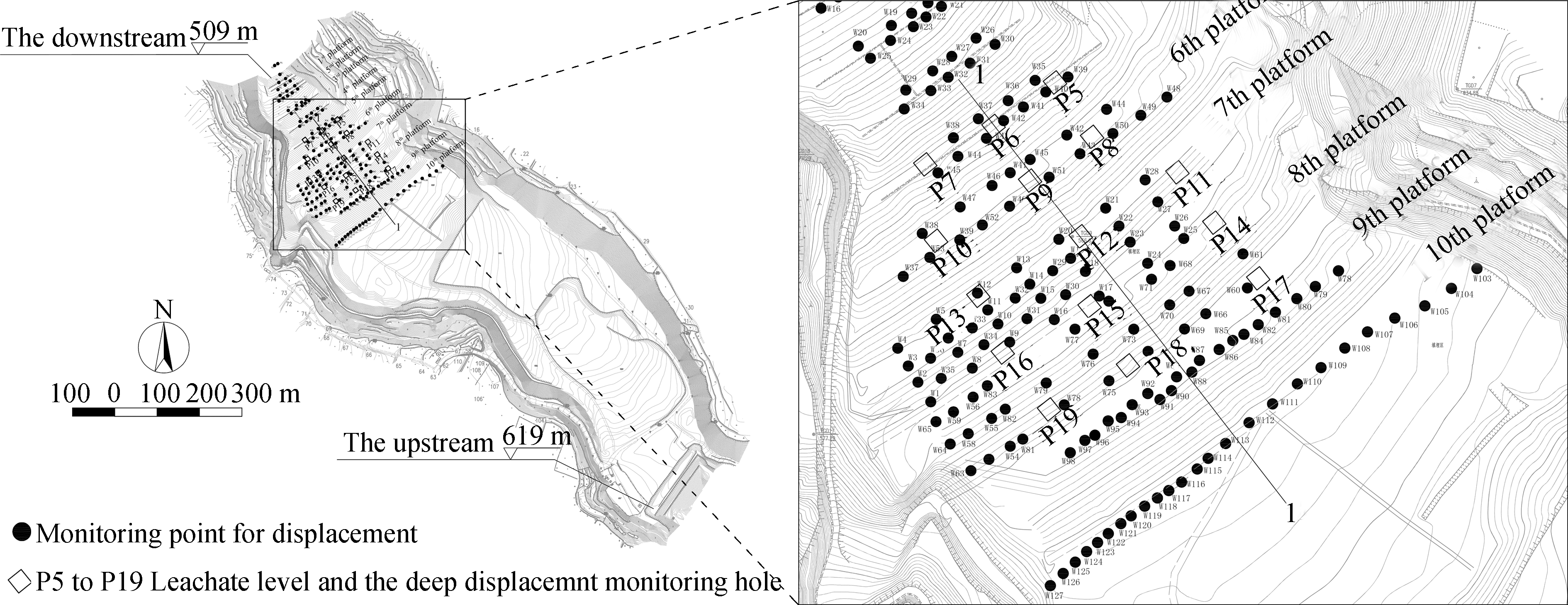
Fig.1 Layout of the landfill
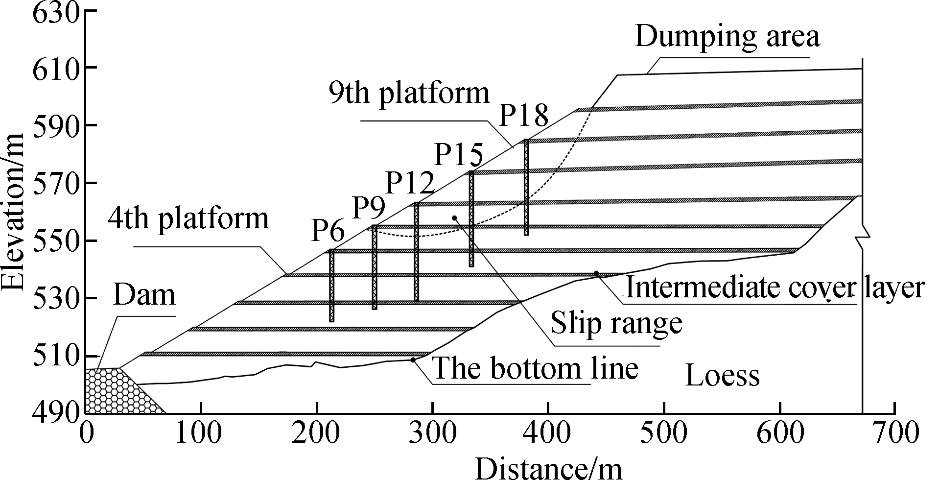
Fig.2 Cross-section of the landfill
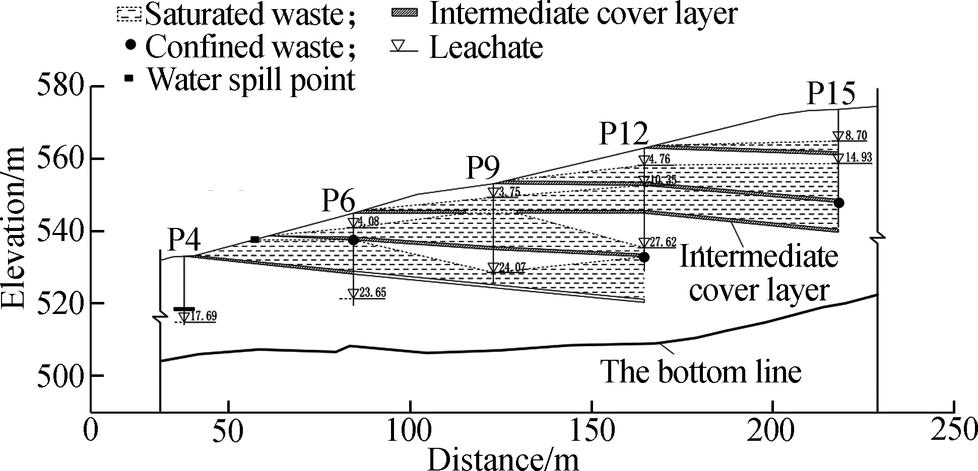
Fig.3 Leachate distribution of the landfill
2 Methods and Results
2.1 The test methods
In order to grasp the whole scope of the slope instability, on-site monitoring of the landfill slope was conducted.Monitoring projects involve: 1)Surface horizontal displacement monitoring, grasping the slippage scope and state of the slope timely; 2)Deep lateral displacement monitoring, providing a basis for identification of slide mode and slippage face depth; 3)Leachate level monitoring, providing an important basis for stability assessment of the landfill.There were 179 monitoring points for surface horizontal displacement (W1-W179, from the 1st platform to the 10th platform).Surface horizontal displacement monitoring was conducted by the measurement of coordinate changes at monitoring points with the application of the TC1700 electronic total station.There were 19 monitoring points for deep lateral displacement (P1-P19, from the 1st platform to the 10th platform).Deep lateral displacement monitoring was conducted by the gradient measurement of a pre-embedded inclinometer tube with the application of an inclinometer.The leachate level was monitored by a steel ruler water level gauge in the pre-embedded inclinometer tube(P1-P19).
2.2 Test results
2.2.1 Monitoring results of surface horizontal displacement
During the period from April 13 to April 30, 2016, landfill work was mainly conducted on the southwest area on the top of the 10th layer of the landfill near the slope.During the period from April 30 to May 6, the dumping area was transferred to the northeast side of the 10th layer, and finally transferred to the upstream region of the landfill.Due to the landfill, the downstream monitoring area showed various degrees of slippage.As stipulated in the technical code for geotechnical engineering of municipal solid waste sanitary landfill[17], warning is required when the superficial displacement rate exceeds 10 mm/d for successive 2 d.As shown in Fig.4, the alarm area reached 13 000 m2 on April 13, mainly located in the slope area of the southwest side of the 10th layer.Due to the intense dumping area and heavy landfill burden, it still filled the municipal solid waste at the southwest area of the 10th layer.Due to the new municipal solid waste load, the alarm area increased to 34 760 m2 and the slip range extended from the 10th layer to the 9th layer.The maximum slip rate of the surface displacement reached 217 mm/d.In order to safely and effectively receive municipal solid waste, landfill work was transferred to the northeast region of the 10th layer.Subsequently, the alert area decreased, from 34 760 m2 on April 19 to 21 800 m2 on May 2.On May 5, the alert area increased to 32 500 m2.Considering that the alarm area was still large, the dumping work was transferred to the upstream region on May 6.Then, the alarm area decreased rapidly.From 23 460 m2 on May 6 to 17 400 m2 on May 11, the alarm area decreased to 5 900 m2 on May 21 and the area was stable after May 25.Judging from the changing law of the dumping region and the alarm area, the main reason of the slippage was the dumping.

Fig.4 Alarm area of the landfill
In order to analyze the influence of MSW load on the slip of the landfill with multiple intermediate covering layers, the surface displacement accumulation diagram of the landfill during the period from March 30, 2016 to May 30 was drawn.In Fig.5, the arrow direction denotes the slippage direction of a displacement monitoring point; the length of the arrow denotes the slippage distance.In order to display the arrow length more clearly, the arrow length was magnified by 10 multiples based on the actual length; the number on the bottom of the arrow denotes the actual slippage distance.Under the influence of the MSW load, there were different degrees of slip in the downstream region.The closer to the dumping area, the greater the degree of slip.Since the landfill operation was carried out at the top of the 10th layer, there was an obvious slip in the 10th layer slope area.During the period from March 30 to May 30, the maximum surface displacement of the 10th platform reached 2.86 m, and the average displacement reached 1.77 m.The sliding degree of the 9th platform is smaller than that of the 10th platform, and the maximum surface displacement of the 9th platform reached 1.62 m, and the average displacement reached 0.54 m.The slipping degree of the 8th platform was the lowest, the maximum surface displacement reached 0.45 m, and the average displacement reached 0.21 m.The slip degree of the southwest region of the same platform was higher than that of the northeast region.The maximum surface displacement point of the 10th platform was located in the southwest region, and the average surface displacement in the southwest region reached 2.49 m, which exceeded 1.10 m in the northeast region.The maximum surface displacement point of the 9th layer was also located in the southwest region, the average slip of the southwest region was 0.71 m, while the northeast region was 0.38 m.
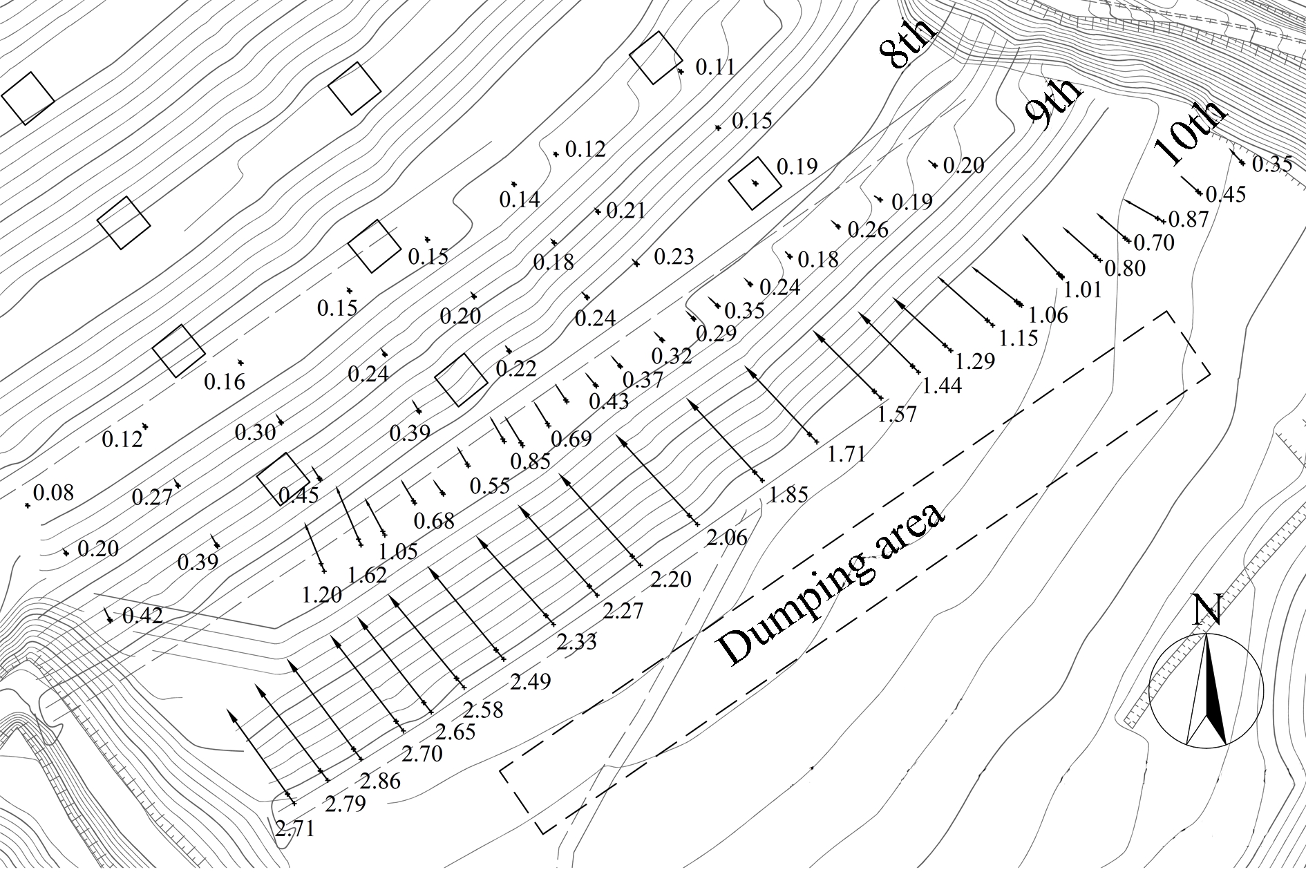
Fig.5 Surface displacement accumulation diagram (unit: m)
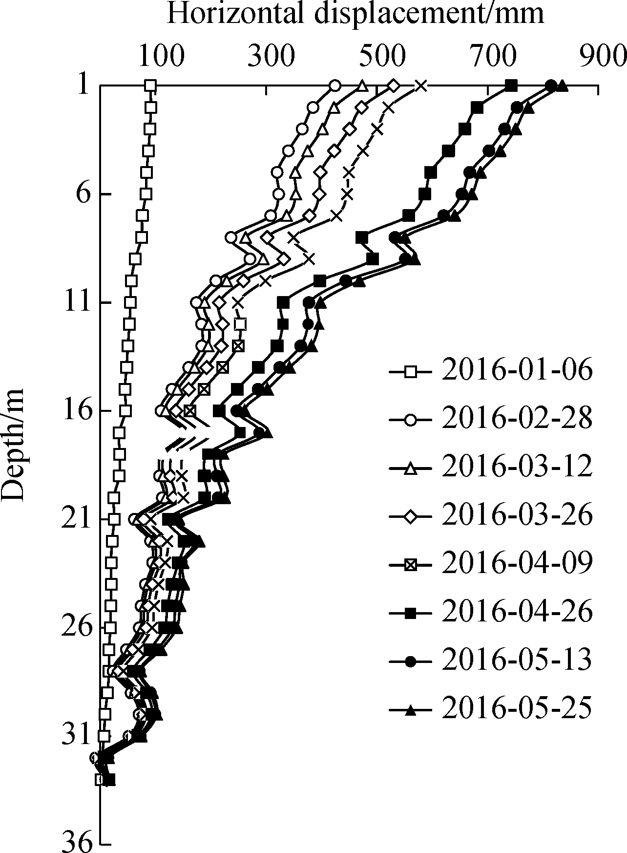
2.2.2 Monitoring results of deep lateral displacement
The deep displacement monitoring holes were arranged as shown in Fig.1, and the monitoring results of representative monitoring points (P18, P15, P12)are plotted in Fig.6.These three holes are located near the 1-1 section.P18 is located in the middle of the 9th platform, which is 40 m from the landfill work area; P15 is located in the middle of the 8th platform, which is about 80 m from the landfill work area; P12 is located in the middle of the 7th platform, which is about 120 m from the landfill work area.The deformation of deep lateral displacement monitoring holes are dominated by tilting deformation, and the displacement decreases with the increase of depth.During the period from January 6 to May 25, the lateral displacement of the P18 hole gradually decreases along the depth, and the maximum cumulative displacement at 1m below the ground is about 0.75 m, and the displacement at the bottom is about 0 m.The P15 hole shows a similar rule.At the same time, the deep slip shows the same phenomenon as the surface slip.The closer to the dumping area, the more obvious the deep slip.From January 6 to May 25, the cumulative displacement at 1 m below the ground of the P18 hole was 744 mm, the average cumulative displacement of the P18 hole was 293 mm.While the cumulative displacement at 1 m below the ground of the P15 hole was 191 mm, the average cumulative displacement of the P15 hole was 112 mm.The cumulative displacement at 1 m below the ground of the P12 hole was 74 mm, the average cumulative displacement of the P12 hole was 35 mm.During April 9 to April 30, the alarm area reached the maximum.The deep displacement during that period also reached the maximum.As shown in Fig.6, during the period from April 9 to April 30, the average cumulative displacement of P18 hole was the largest, which was 67 mm.P15 and P12 also showed the same slip law.
(a)

(b)

(c)
Fig.6 Relationships between deep horizontal displacement and monitoring time.(a)P18;(b)P15; (c)P12
Due to the low permeability coefficient of the intermediate covering layers, the existence of the covering layers caused the multi-layer leachate level in the landfill.Therefore, the effective stress of the multi-layer intermediate cover landfill was obviously different from that of the non-intermediate cover landfill.The effective stress will change at the intermediate covers.The effective stress on the first layer of the multi-layer intermediate cover landfill was the same as that on the non-intermediate cover landfill at the same depth.However, the effective stress in the lower part of the multi-layer intermediate cover landfill was much greater than that of the non-intermediate cover landfill.Due to the barrier of the intermediate cover, the leachate of the upper layer was not continuous with the leachate of the next layer, and the saturated unit weight of the upper layer was converted into the effective unit weight of the next layer.For the municipal solid waste below the leachate level in the non-intermediate cover landfill, as the leachate was continuous, only the buoyant unit weight can be converted into effective stress.Zhan et al.[16] monitored a non-intermediate cover landfill and revealed that the downstream area slipped along the bottom liner system.Therefore, the main slip pattern of the multi-layer intermediate cover landfill was local slip, and the slip patterns of these two types of landfill were quite different.
2.2.3 Monitoring results of leachate level
During the period from April 9 to May 6, 2016, landfill work was mainly conducted on the top of the 10th layer and then transferred to the upstream region.As shown in Fig.7, the leachate level in most of the monitoring wells increased during the period from April 9 to May 6, especially P14 and P19.After the dumping, the leachate level depth of the P14 hole increased from 5.7 m below the ground to 4.5 m below the ground, and the P19 hole increased from 3.3 m below the ground to 4.5 m below the ground.The closer to the dumping area, the greater the increase in the leachate level.The average leachate level of P19, P18 and P17 on the 9th platform was increased by 11% after the dumping, and the average leachate level increase on the 8th and 7th platforms was smaller than that of the 9th platform.During the dumping, the leachate level in the slope area increased, and the surface and the deep displacement points also showed a large slip at the same time, which indicates that there is a positive correlation between the increase of the leachate level and the occurrence of the surface and the deep slip.
As the upper part of the new municipal solid waste was dumped, the lower part of the MSW was squeezed, the porosity was reduced and the leachate in the pores was uplifted.At the same time, new MSW brought a lot of leachate, which resulted in the increase of the leachate level.This phenomenon was consistent with that observed by Chen et al.[18]at other landfills.For the multi-layer intermediate cover landfill, due to the existence of the low permeability of the intermediate covers, the upper part leachate cannot quickly and effectively seep to the lower part, making the upper water level higher.As the landfill dumped from the bottom to the top, it formed the profile, as shown in Fig.2.For the same height of the MSW, the farther away from the slope, the greater the load.In addition, for the same depth, the pressure of the multi-layer intermediate cover landfill was much greater than that of the non-intermediate cover landfill.Therefore, the landfill with multiple intermediate covering layers displayed obvious adverse slope phenomena, as shown in Fig.3.Since the intermediate covers have an inverted slope, the drains, which were built above the covers, must also be inverted slopes.Therefore, the leachate flowed from the outside to the inside.The leachate inside the landfill cannot be effectively drained, and so the leachate level was high.
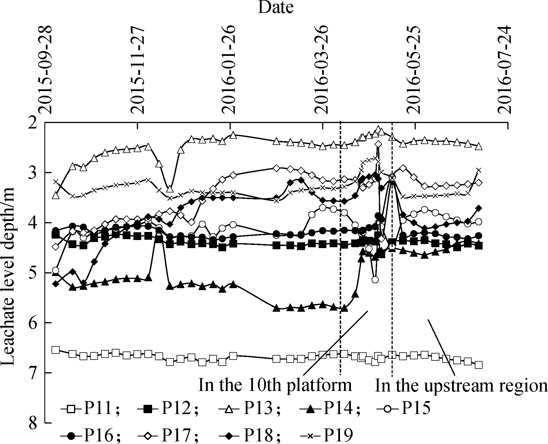
Fig.7 Curves between leachate level depth and monitoring time
3 Analysis of Slope Slip at the Landfill with Multiple Intermediate Covering Layers
In this paper, the SLOPE/W module developed by Geo-Studio Company was adopted to conduct an inverse analysis of instable slopes.In addition to the function of automatically searching a non-arc slippage face, the SLOPE/W can also search a slippage face which passes through a soft interlayer or an interface.The widely adopted Morgenstern-Price method was selected for the analysis of calculating the slope stability safety factor.The analysis model was established according to the relief map of Section 1-1 in April, 2016.The leachate data, which was used in the computation model, was derived from the total leachate level in April, 2016 and the results of multiple water levels were obtained by on-site reconnaissance in 2015, as shown in Fig.8.The strength parameters of each material are listed in Tab.1, involving the bottom loess layer, HDPE membrane, dam and waste.Waste strength parameters adopted in this paper were mainly subject to the Technical Code for Geotechnical Engineering of Municipal Solid Waste Sanitary Landfill (CJJ176—2012).These parameters were determined according to different ages and depths.Waste was classified into new waste and old waste.
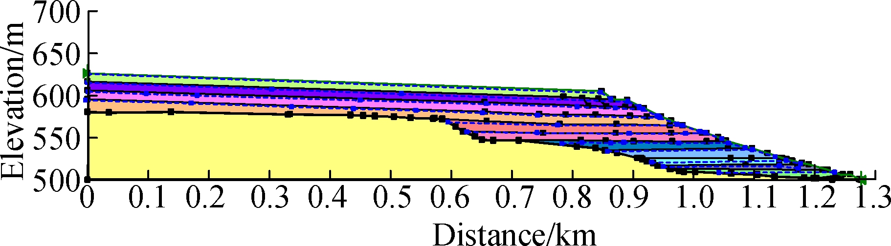
Fig.8 The analysis model
Tab.1 Shear strength parameters for materials

MaterialUnitweight/(kN·m-3)Angleofinternalfriction/(°)Cohesion/kPaDam192810Loesslayer192230HDPEmembrane1213Newwaste12208Oldwaste15300
As shown in Tab.2, the monolithic stability of the landfills without the intermediate covering layer and the landfill with multiple intermediate covering layers were analyzed.The same models were adopted in the analysis, whereas the two landfills differed in leachate level forms.The landfill without the intermediate covering layer only had one leachate level, while the landfill with intermediate covering layers had 11 leachate levels.Nevertheless, both of them had the same leachate level height sum.Analysis results show that the monolithic stability safety factor of the landfill without the intermediate covering layer is 1.127, which is smaller than the stability safety factor of 2.797 of the landfill, with intermediate covering layers.The reason is that the effective stress of the landfill with intermediate covering layers exceeded that of the landfill without the intermediate covering layer.
Tab.2 The monolithic stability safety factor of the landfills

LandfilltypeSafetyfactorLandfillwithoutintermediatecoveringlayer1 127Landfillwithmultipleintermediatecoveringlayers2 797
Qian et al.[19] surveyed 15 instability damage cases which occurred in worldwide large landfills over the last 20 years.They found that 11 accidents were caused by the monolithic slip of the landfill, which was damaged along the liner system; only four accidents were caused by the shallow-layer damage generated from slip inside the waste body.They pointed out that the damage form of all the landfills containing geo-membrane liner was caused by the monolithic slip of the damaged face, which was damaged along the liner system.Zhan et al.[16] also investigated the slippage accident of Shenzhen Xiaping Landfill.After analyzing the on-site slippage data, they pointed out that the slip of the landfill was the monolithic slippage caused by damage along the liner system.These conclusions were mainly applicable to the landfill without the intermediate covering layer.As for the landfill with intermediate covering layers, compared with the monolithic slip, a shallow-layer slip may more easily occur.As shown in Tab.3, the stability safety factor is 1.017 for the shallow-layer damage, which is mainly caused by slippage inside the waste body of the landfill with intermediate covering layers.As for the monolithic slip caused by damage along the liner system, the stability safety factor is 2.797.
Tab.3 Stability safety factor of the landfill with multiple intermediate covering layers

StabletypeSafetyfactorMonolithicstability2 797Localstability1 017
4 Analysis of the Effects of Control Measures for Slippage of the Landfill
Korner and Soong[20] conducted statistics for the landslides of 10 landfills in different places in the world.They found that 70% of the landslides were caused by high leachate level in the landfill, of which only three landslides were caused by heavy rainfall.Zhan et al.[16] found that sharp and quick rise of leachate level caused by heavy rainfall was the factor for the accident.Hence, the measures of stability control mainly focused on leachate drainage at the landfill.The effects of stability control measures for the landfill under different leachate drainage measures were analyzed.
4.1 Leachate drainage on the top layer
Zhan et al.[16] installed pumping vertical wells on the top of landfill in order to realize forced reduction of leachate level.Results show that the level of the landfill decreased by 1 to 4 m, and the slippage of the landfill was effectively controlled.As shown in Tab.4, the influences of the top-layer leachate drainage measure on the stability of the landfill with multiple intermediate covering layers were analyzed.Results show that the effect of the top-layer leachate drainage measure on the stability of landfill with multiple intermediate covering layers was not obvious.Specifically, the stability safety factor of the landfill with the top-layer leachate drainage of 5 m was the same as that untreated by the water level reduction measure.The safety factor of the landfill with a top-layer
Tab.4 Influences of the leachate drainage on the top layer on the stability of landfill

StabilitycontrolmeasuresSafetyfactorToplayerleachatedrainageof1m1 017Toplayerleachatedrainageof5m1 017Toplayerleachatedrainageof10m1 023Toplayerleachatedrainageof20m1 057
leachate drainage of 20 m was 1.057, which was increased by 4%, while the influences were not obvious.The top-layer leachate drainage measure was applicable to the stability control of a landfill without the intermediate covering layer, but it is inapplicable to the stability control of a landfill with multiple intermediate covering layers.
4.2 Leachate drainage in different layers
As shown in Tab.5, the influences of the leachate drainage in different layers on the landfill with multiple intermediate covering layers were analyzed.Leachate drainage in different layers refers to leachate level reduction implemented in each waste layer.In Tab.5, the layered leachate drainage of 1 m indicates the leachate drainage of 1 m to each waste layer.As for the landfill with the layered leachate drainage of 1 m, the stability safety factor was 1.114, which was increased by 10%.As for the landfill with layered leachate drainage of 3 m, the stability safety factor was 1.386, which was increased by 36%.The leachate drainage in different layers can effectively enhance the stability of landfill with multiple intermediate covering layers.Taking the construction into account, it was difficult to drain the leachate far from the slope area.Especially for some landfills with a length exceeding 1 000 m, it is very difficult to conduct leachate drainage of saturated waste on each waste layer remote from the slope area.
Tab.5 Influences of the leachate drainage in different layers on the stability of landfill
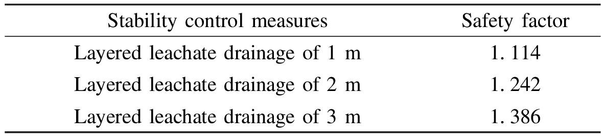
StabilitycontrolmeasuresSafetyfactorLayeredleachatedrainageof1m1 114Layeredleachatedrainageof2m1 242Layeredleachatedrainageof3m1 386
4.3 Near-slope leachate drainage
As shown in Tab.6, the influences of the near-slope leachate drainage on the stability of the landfill with multiple intermediate covering layers were analyzed.The leachate drainage in near-slope areas means to drain the leachate in each layer near the landfill slope.In Tab.6, the near-slope leachate drainage of 10 m indicates that the leachate in each layer within the 10 m scope near the landfill slope was drained.After the leachate in each layer within the 10 m scope near the slope was drained, the stability safety factor of the landfill was 1.102, which was
Tab.6 Influences of the near-slope leachate drainage on the stability of landfill
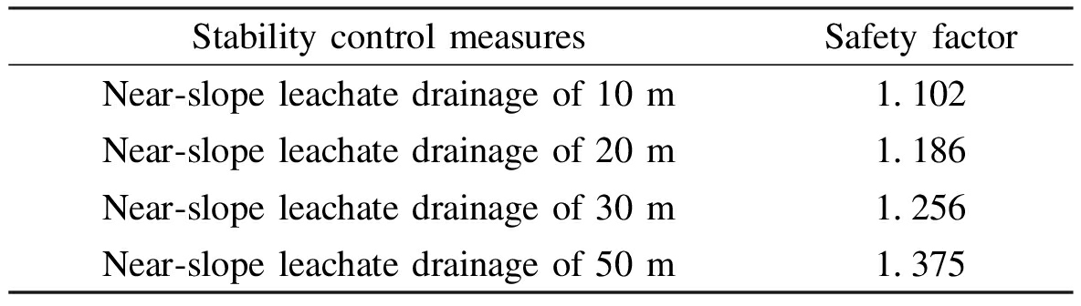
StabilitycontrolmeasuresSafetyfactorNear⁃slopeleachatedrainageof10m1 102Near⁃slopeleachatedrainageof20m1 186Near⁃slopeleachatedrainageof30m1 256Near⁃slopeleachatedrainageof50m1 375
increased by 8%.After the leachate in each layer within the 50 m scope near the slope was drained, the stability safety factor of the landfill was 1.375, which was increased by 35%.The near-slope leachate drainage can effectively enhance the stability of the landfill with multiple intermediate covering layers.In comparison with the layered leachate drainage, the near-slope leachate drainage can be easily realized in the landfill.This measure can be realized by arranging leachate horizontal drainage wells in the near-slope area.
5 Conclusions
1)During the period from April 9 to May 26, the slope slip occurred at the landfill and the maximum slip area was 34 760 m2.Dumping was the main reason for its instability, and the failure mode was the local sliding inside the landfill.The closer to the dumping area, the greater the degree of the slip and the more significantly the leachate level rises.
2)The average surface horizontal displacement of the 10th platform was 1.77 m.The slip degree of the southwest region was more than that of the northeast region on the same platform.The average displacement in the southwest region of the 10th platform was 2.49 m, which was 1.10 m in the northeast region.
3)The deep lateral displacement monitoring holes were dominated by tilting deformation, and the displacement decreases with the increase of depth.During the period from January 6 to May 25, the average lateral displacement in P18 hole was 293 mm, while the P15 hole was 112 mm and the P12 was 35 mm.
4)The results of the stability analysis showed that leachate drainage in different layers and near-slope leachate drainage were suitable for the stability control of the multi-layer intermediate cover landfill.The effect of near-slope leachate drainage on stability control was obvious.
References
[1]Liu S Y, Zhan L L, Hu L M, et al.Environmental geotechnics: State-of-the-art of theory, testing and application to practice [J].China Civil Engineering Journal, 2016, 49(3): 6-30.(in Chinese)
[2]Li Y C, Cleall P J, Ma X F, et al.Gas pressure model for layered municipal solid waste landfills [J].Journal of Environmental Engineering, 2012, 138(7): 752-760.DOI:10.1061/(asce)ee.1943-7870.0000533.
[3]Feng S J.Static and dynamic strength properties of municipal solid waste and stability analysis of landfill [D].Hangzhou: School of Civil Engineering and Architecture, Zhejiang University, 2005.(in Chinese)
[4]Stoltz G, Gourc J, Oxarango L.Liquid and gas permeabilities of unsaturated municipal solid waste under compression [J].Journal of Contaminant Hydrology, 2010, 118(1/2): 27-42.DOI:10.1016/j.jconhyd.2010.07.008.
[5]Larson J, Kumar S, Gale S A.A field study to estimate the vertical gas diffusivity and permeability of compacted MSW using a barometric pumping analytical model [J].Waste Management & Research, 2012, 30(3): 276-284.DOI:10.1177/0734242X11424592.
[6]Giri R K, Reddy K R.Slope stability of bioreactor landfills during leachate injection: Effects of heterogeneous and anisotropic municipal solid waste [J].Waste Management & Research, 2014, 32(3): 186-197.DOI:10.1177/0734242X14522492.
[7]Shariatmadari N, Sadeghpour A H, Mokhtari M.Aging effect on physical properties of municipal solid waste at the Kahrizak Landfill, Iran [J].International Journal of Civil Engineering, 2015, 13(1): 126-136.
[8]Li X L, Shi J Y.Stress-strain behaviour and shear strength of municipal solid waste [J].KSCE Journal of Civil Engineering, 2016, 20(5): 1747-1758.DOI:10.1007/s12205-015-0268-5.
[9]Feng S J, Gao K W, Chen Y X, et al.Geotechnical properties of municipal solid waste at Laogang Landfill, China [J].Waste Management, 2017, 63:354-365.DOI:10.1016/j.wasman.2016.09.016.
[10]Palmeira E M, Lima N R, Mello G R.Interaction between soils and geosynthetic layers in large-scale ramp tests [J].Geosynthetics International, 2002, 9(2): 149-187.DOI:10.1680/gein.9.0214.
[11]Carbone L, Gourc J P, Carrubba P, et al.Dry friction behaviour of a geosynthetic interface using inclined plane and shaking table tests [J].Geotextiles and Geomembranes, 2015, 43(4): 293-306.DOI:10.1016/j.geotexmem.2015.05.002.
[12]Huang Y, Zhu C Q.Simulation of flow slides in municipal solid waste dumps using a modified MPS method [J].Natural Hazards, 2014, 74(2): 491-508.DOI:10.1007/s11069-014-1194-4.
[13]Ruan X B, Sun S L, Liu W L.Effect of the amplification factor on seismic stability of expanded municipal solid waste landfills using the pseudo-dynamic method [J].Journal of Zhejiang University:Science A, 2013, 14(10): 731-738.
[14]Annapareddy V S R, Pain A, Sarkar S.Seismic translational failure analysis of MSW landfills using modified pseudo-dynamic approach [J].International Journal of Geomechanics, 2017, 17(10): 04017086.DOI:10.1061/(asce)gm.1943-5622.0000990.
[15]Ering P, Babu G L S.Slope stability and deformation analysis of bangalore MSW landfills using constitutive model [J].International Journal of Geomechanics, 2016, 16(4): 04015092.DOI:10.1061/(asce)gm.1943-5622.0000587.
[16]Zhan L T, Guan R Q, Chen Y M, et al.Monitoring and back analyses of slope failure process at a landfill [J].Chinese Journal of Rock Mechanics and Engineering, 2010, 29(8): 1697-1705.(in Chinese)
[17]Ministry of Housing and Urban-Rural Development of the People’s Republic of China.CJJ176—2012 Technical code for geotechnical engineering of municipal solid waste sanitary landfill[S].Beijing: China Architecture & Building Press, 2012.(in Chinese)
[18]Chen Y M, Lan J W, Li Y C, et al.Development and control of leachate mound in MSW landfills [J].Chinese Journal of Rock Mechanics and Engineering, 2014, 33(1): 154-163.(in Chinese)
[19]Qian X D, Koerner R M, Gray D H.Geotechnical aspects of landfill design and construction [M].Upper Saddle River, NJ, USA: Prentice Hall, 2002: 431-436.
[20]Koerner R M, Soong T Y.Stability assessment of ten large landfills failures [C]//Advances in Transportation and Geoenvironmental Systems Using Geosynthetics.Denver, USA, 2000: 1-38.DOI:10.1061/40515(291)1.