Yang Nan,Zhu Zimin Yuan Tiejiang.Research on resonance fault caused by dc magnetic biasing in ultra high voltage transformer with parallel static var compensator[J].Journal of Southeast University(English Edition) ,2020,36(03):301-312.[doi:10.3969/j.issn.1003-7985.2020.03.008]

针对直流偏磁引起的并联TCR+FC型SVC特高压变压器谐振问题,基于MATLAB/Simulink平台,构建了用于阻抗频率特性分析的并联SVC的特高压变压器仿真模型与基于经典Jiles-Atherton磁滞理论的变压器场路耦合仿真模型.理论和仿真结果表明,特高压变压器并联谐振的形成机理为直流偏磁情况下,并联SVC投入运行时,变压器低压侧谐振点趋近于4次谐波.基于此,提出一种谐振控制思路,即在原FC滤波支路上串联含旁路开关的电抗器.在直流偏磁下,旁路开关的切断可以提升FC滤波支路的串抗率,从而改变并联谐振点.并针对此谐振控制方法带来的7次谐波问题,提出了锁定TCR支路控制角在130°~180°区间的改进措施.以某750 kV特高压变压器为例,验证了谐波控制方法对特高压变压器并联谐振的抑制作用,仿真结果表明谐振故障机理的分析及其谐振控制方法是正确和可行的.
For dealing with the resonance fault of ultra-high voltage transformers(UHVTs)with the parallel thyristor controlled reactor(TCR)+ the filter compensator(FC)type static var compensator(SVC)caused by dc magnetic biasing, a simulation model of UHVT with parallel SVC for the frequency analysis of the impedance characteristics and a magnetic-field coupling model for UHVT based on classic Jiles-Atherton hysteresis theories are constructed based on the MATLAB/Simulink platform. Both the theoretical and simulation results prove that the resonance fault is caused by the resonance point on the low-voltage side of the transformer, which will approach the 4th harmonic point under magnetic biasing. Based on the fault analysis, a new resonance control method is proposed by adding reactance with by-pass switches in series with FC branches. Under dc magnetic biasing, the cutoff of the by-pass switch will increase the series reactance rate of the FC branches and change the resonance point. In order to avoid the 7th harmonic increasement caused by this method, the firing angle of the TCR branches is locked between 130° and 180°. The effect of the proposed method is validated by the simulation model of a 750 kV UHVT and the results show that the mechanism analysis of the resonance fault is correct and the resonance control method is valid.
With the rapid development of the large-scale ultra-high voltage cross-area interconnected power grid, the dynamic reactive power compensator such as static var compensator(SVC), which is commonly deployed in parallel to the power transformer, has been gradually applied to the power system. Due to the low direct-current resistance of the transmission line and frequent turbulence of the self-coupling transformer, dc magnetic bias current can be found in ultra-high voltage girds frequently[1]. When magnetic bias current flows through ultra-high voltage power transformers(UHVTs), an odd number harmonics current will be generated and cause potential resonance to the SVCs connected parallel to UHVTs. This abnormal operation of SVC can either cause a decrease in its reactive power supply ability or cause a complete shut-down of the device, which can further reduce system stability[2-3]. Therefore, necessary attention should be paid to this topic.
Most research focused on studying the effect of magnetic bias current on the static power component such as transformers and reactive compensation capacitors(RCCs)connected to the transformer [4-6]. The influence of magnetic biasing on dynamic power compensators such as SVC is rarely discussed.
In Ref.[7], the magnetic bias effect on the winding current of UHV is simulated with the edge finite element method. The result shows that the distortion of the winding current is directly linked to the magnetic biasing current. Harmonic amplification is very detrimental in this case. However, the research is only carried out with a resistive load and focuses only on the transformer itself.
The ability of power transformers to withstand the dc bias is studied by a novel analytical method in Ref.[8]. The conclusion pointed out that the peak values of the exciting currents at the saturation conditions caused by the dc biasing and the overvoltage are directly linked. A magnetic biasing treatment plan is proposed in Ref.[9]. The authors developed a 3-port converter topology and utilized dc modulation magnetic flux for compensating for the dc bias problem.
In Refs.[10-11], the influence of bias current on the reactive power supply ability of the transformer was studied. Researchers pointed out that under magnetic biasing, the reactive power loss of the transformer will increase dramatically with the bias current, reducing its equivalent impedance. During this process, a large proportion of even number harmonics will be generated,significantly distorting the excitation current. If the reactive power compensator is still active in this case, the frequency characteristic of the impedance will be changed as well as its parallel resonance point. The resonance of even number harmonics may occur on the capacitor branch of the power compensator and be amplified under the magnetic biasing.
In Ref.[12], Yang et al. pointed out that the resonance fault in RCC can be avoided by increasing the series reactance rate under the magnetic biasing. However, this method cannot be directly applied to SVC devices due to the strict high-order harmonic requirement.
Refs.[13-14] pointed out that the increase of reactive power loss caused by dc magnetic biasing on a specific node point in a UHVTS can reach 200 Mvar under strong magnetic storm conditions. Any resonance or amplification under such a condition is a dangerous threat to the grid. Without a proper control method, this can lead to a complete shutdown of the system.
This paper focuses on the potential resonant and harmonic amplification problems of the UHVTs with TCR+FC type SVCs under the influence of dc magnetic bias current. The characteristics of the SVC are investigated, and the causes of the resonance and amplification of harmonics are explained. The corresponding control methods are proposed. MATLAB/Simulink models for simulating the characteristics of the ultra-high voltage transformer with parallel SVC(UHVT-PSVC)and magnetic coupling feature under dc magnetic biasing are constructed. The results of the simulation and the corresponding configurations of the control method are provided.
1 Resonance Fault in UHVT with Parallel SVC under Magnetic Biasing1.1 Mechanism of resonance faultStatic var compensator type TCR+FC consists of thyristor-controlled reactors(TCRs)and filter compensators(FCs). It is connected to the low-voltage side of the transformer as shown in Fig.1. In Fig.1, In is the equivalent harmonic current source caused by dc magnetic biasing. Branches 1#,2# and 3# are the 3rd/5th/7th order FC branches for SVC. By converting the impedance of the high/medium side to the low-voltage side, the total equivalent impendence of the transformer node is calculated as
Zsys=(Z'total//Z'Q)//ZSVC(1)

Fig.1 Equivalent circuit of UHVT-PSVC with dc magnetic biasing on the low-voltage side
Z'total consists of the resistances of the windings, leakage reactance and the excitation impedance Zm of the transformer. Winding resistances are negligible during the normal operation of the transformer. The reduction of Zm is the main reason for the increasing reactive power loss Qdc caused by the saturation of the transformer under magnetic biasing. Therefore, Qdc can be treated as the reactive power load parallel to the primary side of the transformer. By converting to the low-voltage side, this loss is expressed by impedance Z'Q. The impedance of SVC is composed of TCR branch impedance ZTCR and FC branch impedance ZFC. The mechanism of the resonance fault in the transformer under magnetic biasing is shown in Fig.2. The series reactance rate of the parallel capacitor branch is calculated as K=XL/XC.
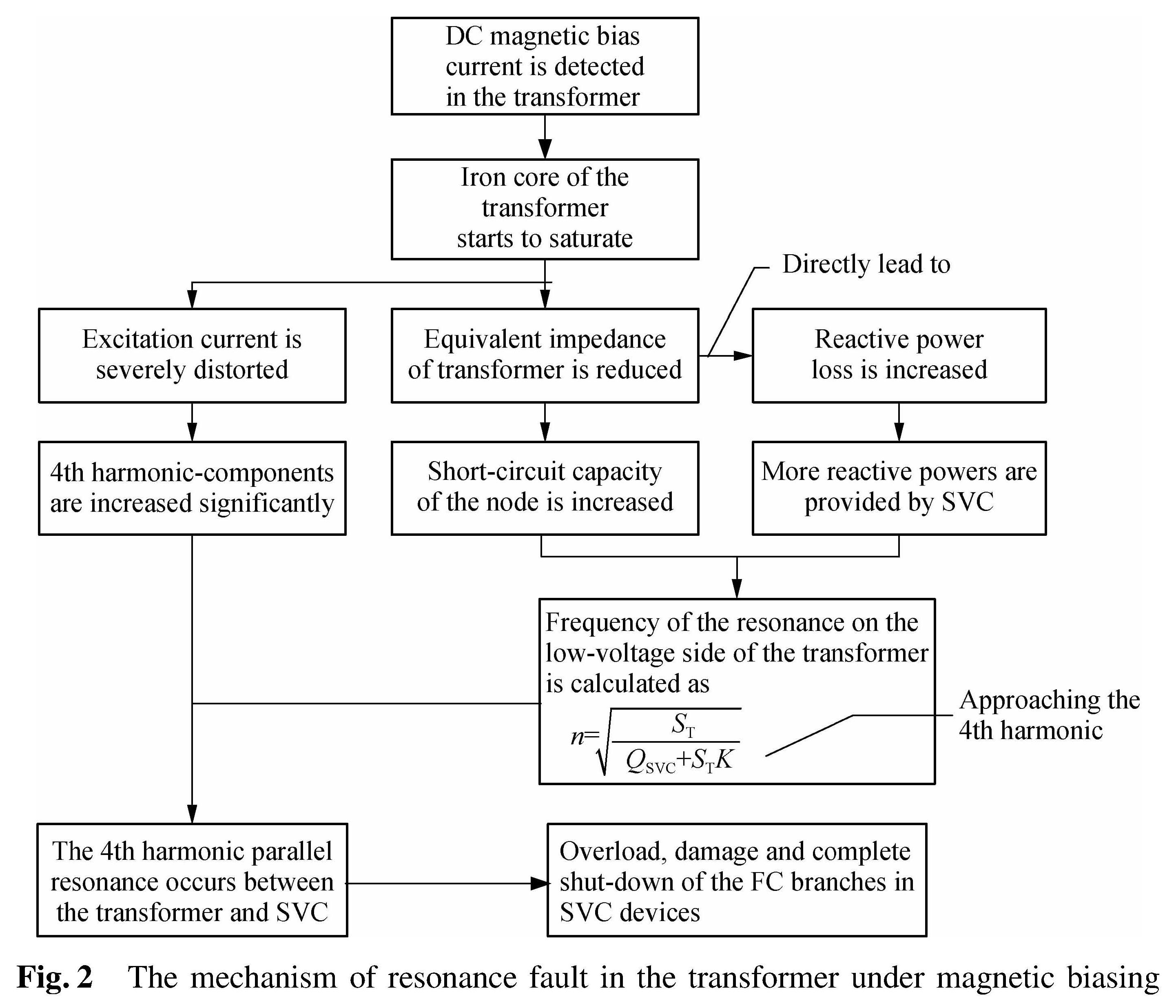
Fig.2 The mechanism of resonance fault in the transformer under magnetic biasing
As the maximum value of ZSVC has its limitation, the presence of Z'Q will reduce the equivalent impedance of the transformer and increase the short-circuit capacity of the node. The order of the system parallel resonance point is also increased, which can be estimated by
n=((ST)/(QSVC+STK))1/2(2)
where QSVC is the reactive power of SVC; ST is the short-circuit node capacity; and K is the series-reactance rate. Usually, the series-reactance rate of capacitors in the power system is assumed to be 12%-13% or 5%-6%(for the 3rd and 5th harmonics). However, due to the harmonic requirement, the series-reactance rate of the SVC is usually lower than these values. If the SVC only provides reactive power from capacitor branches and FC branches are tuned precisely to the 3rd,5th and 7th harmonics, the input impedance characteristics on the low-voltage side of a 750 kV transformer without magnetic biasing are shown in Fig.3 when FC branches are activated.
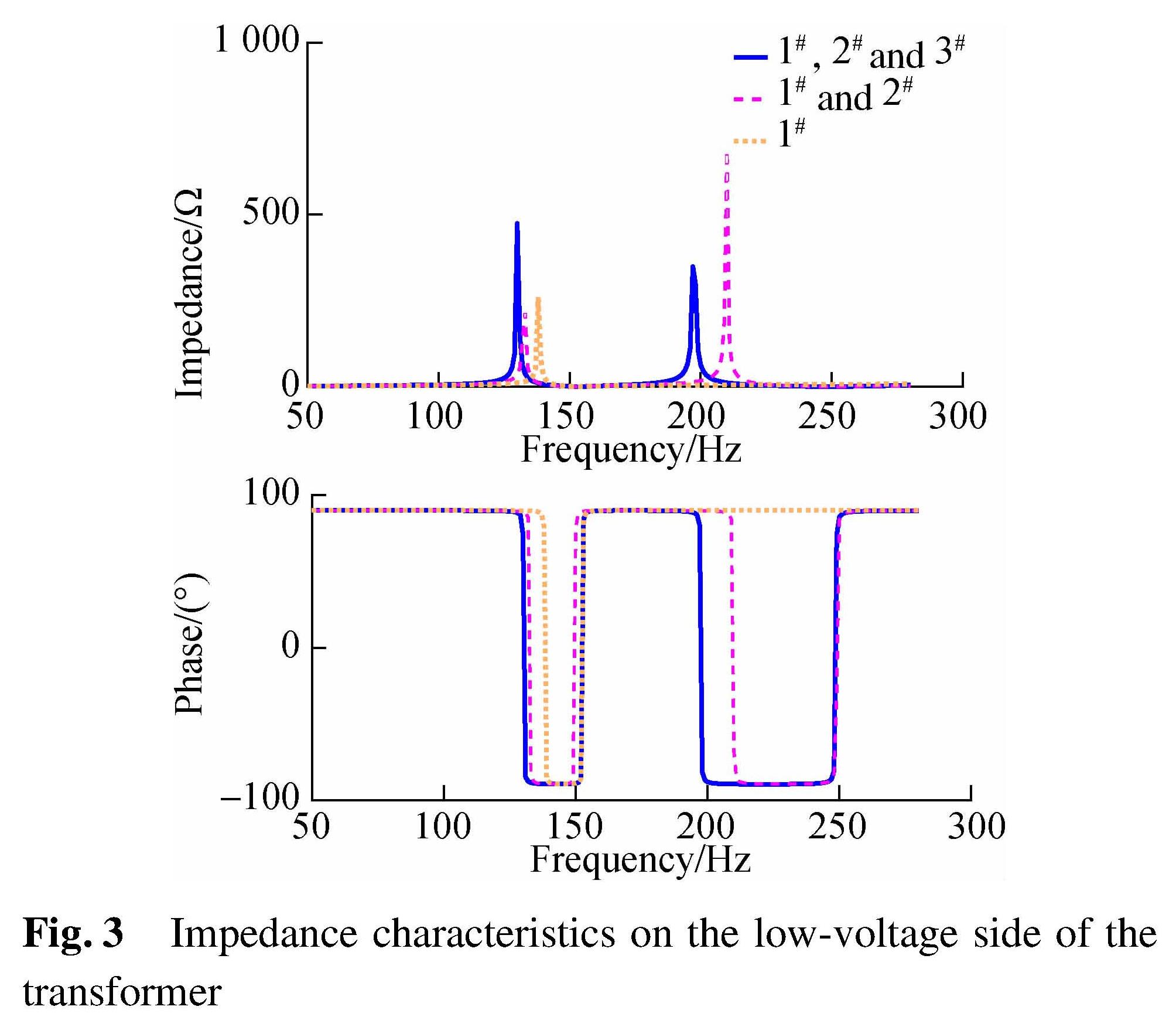
Fig.3 Impedance characteristics on the low-voltage side of the transformer
With the connection of 2 FC branches on the low-voltage side of the transformer, the 2nd parallel resonance point can be observed around 200 Hz as shown in Fig.3. The frequency of the resonance point will be reduced while the active number of FC branches increases. Combined with the results from Fig.2, it is fair to say that the change of equivalent impedance caused by dc magnetic biasing and the impedance characteristics of the SVC devices are two major reasons for the resonance faults. The 4th harmonic parallel resonance is most likely to occur when the FC branches are tuned to the 3rd, 5th and 7th harmonics and all 3 sets of FC branches are switched on. With the increase in the series-reactance rate, the possibility of parallel resonance with 2 FC branches will also be increased.
By considering the possible harmonic amplification of the harmonic current in FC branches when SVC is activated, two operation methods of SVC can be categorized under magnetic biasing:
1)Method 1. When active FC branches are just enough to compensate for the reactive power loss Qdc , or the SVC reaches its maximum capability, the SVC can be treated as parallel capacitors. Assuming that only one FC branch 1# is switched on and the TCR branch remains off, by ignoring the small branch resistance, the n-th harmonic reactance of the FC branch is calculated as
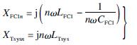 (3)
(3)
Since the SVC is in parallel with equivalent impedance on the system side ZTsys, the n-th harmonic current on the 1# branch is calculated as
I·FC1n=j(XTsysn)/(XFC1n+XTsysn)I·n(4)
where XFC1n is the reactance of the 1# FC branches in SVC; XTsysn is the reactance of the system side; I·n is the total n-th harmonic current on the SVC.
If XFC1n<0, the amplitude of the n-th harmonic in the FC branch of SVC device will be amplified, causing potential series-resonance with the leakage reactance on the system side.
If XFC1n+XTsysn≈0, system parallel resonance occurs and amplifies both I·FCn and I·n. If the multiple numbers of FC branches are switched on but not all of them are inductive(i.e. XFCin<0, XFC(i+1)n>0 or XFCin>0, XFC(i+1)n<0), harmonic amplification is also inevitable between FC branches.
2)Method 2. If the SVC devices are sufficient to compensate for reactive power loss Qdc and follow
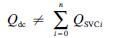 (5)
(5)
The capacitive power compensated by SVC is now composed of two parts: QTCR and QFCi. In this mode, the harmonic current in the FC branch is calculated as
I·FC1n=j(XTsysn)/(XFC1n+XTsysn)I·n(6)
In this case, the connection of the TCR branches will enhance the absolute value of the system impedance, increasing the 5th and 7th harmonic content of the SVC device. Actions should be taken to reduce the effect of these harmonics.
1.2 Resonance fault control procedureThe analysis in Section 1.1 indicates that the system parallel resonance point can be altered by changing the series-reactance rate K. This can be used to prevent the potential harmonic amplification problem in FC branches. When configuring the n-th harmonic series reactance of the FC-branch, K should follow the equation below:
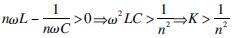 (7)
(7)
If even number harmonics and their resonance points change under the magnetic biasing are taken into consideration, K value must be set to be greater than 6.25%. This will keep the reactance of FC branches inductive in the 4th order harmonic[15]. However, by considering the potential frequency shift of system parallel resonance and equipment characteristics, K should be set to be 7% to prevent resonance and harmonic amplification under magnetic biasing.
However, the rate K of the 7th order harmonic FC branch is only 2.04% in the theoretical calculation, which is insufficient for normal operation under magnetic biasing.To ensure that rate K satisfies the requirement of both normal and magnetic biasing, an improved structure of FC branches is proposed as shown in Fig.4. By-pass switch K1 is used to control the rate K of the SVC under both normal and magnetic biasing conditions. When switched off under magnetic biasing, rate K in the full branches can be increased to 7%(i.e. 7%=ω2L1+L2C). When switched on, the additional reactance L1 is short-circuited and rate K can be restored to normal.

Fig.4 An improved structure of the FC branch
As mentioned in operation method 2, the activation of TCR branches will increase the impedance on the low-voltage side of the transformer. As the impedance of FC branches is also increased, the 5th and 7th harmonic content in the transformer should be properly controlled in this case. By setting the firing angle(α)of TCR between 130° and 180°, the corresponding change of QTCR can be limited below 0.25 p.u.. As the capacity of TCR is slightly greater than the sum of all FC branches in the SVC, TCR can provide 1/3 more inductive power than the sum of all reactive power provided by FC branches. It should cover the requirements in practical use. The resonance fault control procedure of a UHVT-PSVC under dc magnetic biasing is shown in Fig.5.
2 Model Construction of a UHVT with Parallel SVC under Magnetic Biasing2.1 Equivalent circuit of a UHVT with parallel SVCCurrently, most UHVTs applied to 500 kV and the above voltage rate are single-phase self-coupling transformers. The system is 3-phase balanced during normal operations and the impedance change in each phase is almost identical. Therefore, a single-phase UHVT-PSVC simulation model for impedance/frequency analysis is constructed based on MATLAB/Simulink as shown in Fig.6.
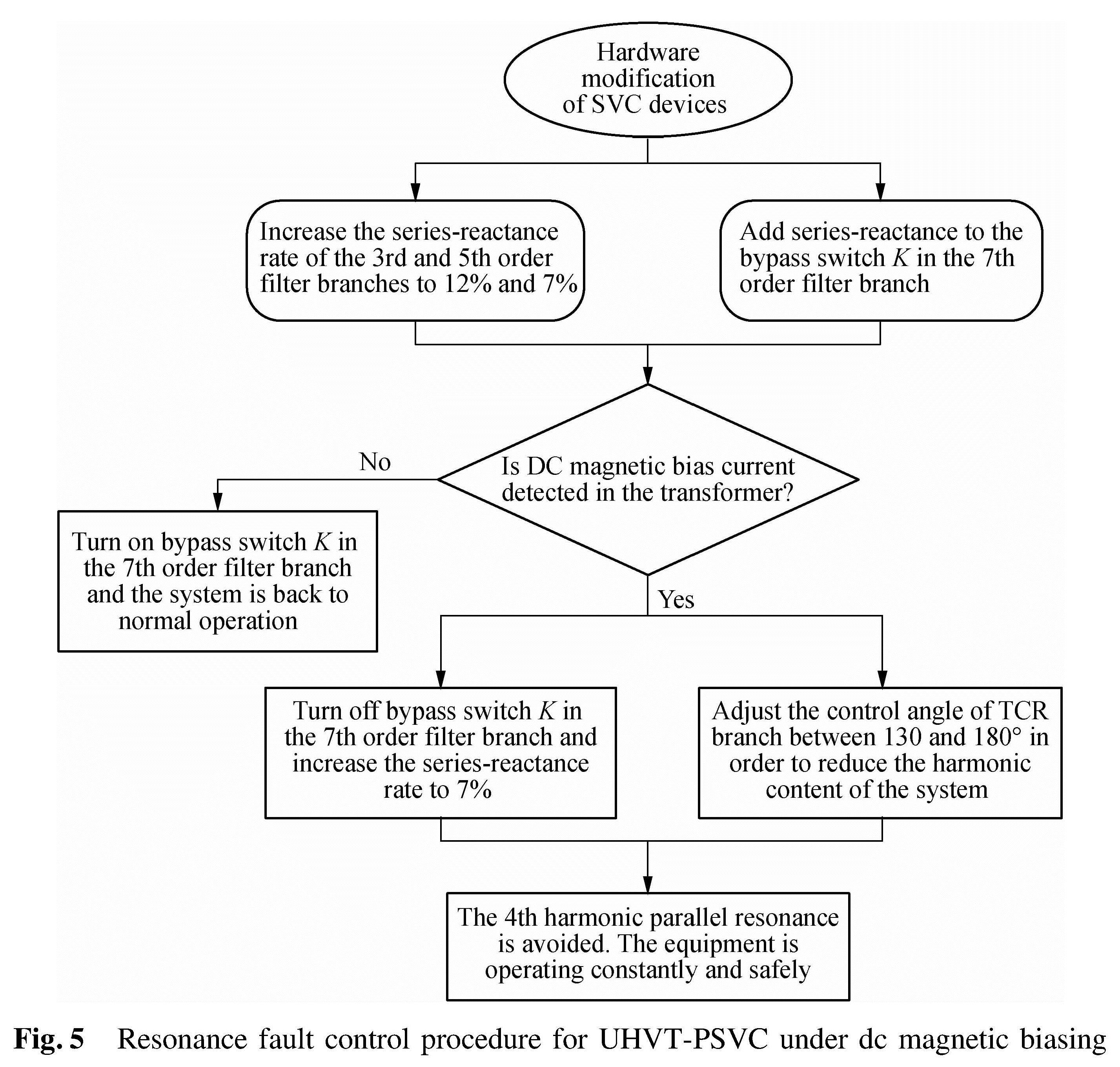
Fig.5 Resonance fault control procedure for UHVT-PSVC under dc magnetic biasing

Fig.6 The equivalent circuit model of a single-phase UHVT-PSVC
No single-phase self-coupling transformer is available in MATLAB/Simulink. Therefore, the ideal single-phase 3-column transformer, whose primary side is connected to its secondary side, is used as a substitution. As shown in Fig.6, the “Priminal” is the primary side of the transformer, and “Secondary” is the medium-voltage side of the transformer. SVC is connected to the low-voltage side of the transformer through single-phase transmission lines.
Block impedance vs. frequency uses a harmonic current source with parallel resistance as the harmonic voltage source. The impedance/frequency characteristics of the 2-terminal time-invariant system are obtained by calculating X=Uz(s)/Iz(s). The data is then transported to the Impedance vs. Frequency Measurement program in powergui block to acquire the impedance/frequency characteristics.
The winding settings of ODFPS-500000/750 UHVT-PSVC are shown in Tab.1. The total compensation capacity of SVC devices is 180 Mvar and the series-resistance in the FC-branch of SVC is 0.08 Ω. When TCR is not switched on, the series-reactance rates of 3 branches are 12%,6% and 6%. The input impedance characteristics and impedance angles with different FC branches are shown in Fig.7.
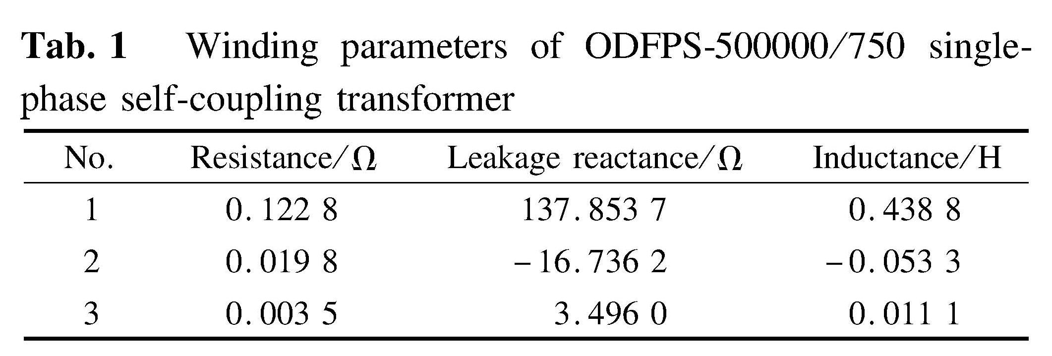
Tab.1 Winding parameters of ODFPS-500000/750 single-phase self-coupling transformer
Compared with Fig.3, it is obvious that the change of K is very important for the input impedance characteristics. With the connection of FC branch 2# and 3#, both amplitude and the frequency range of the parallel system resonance, especially those around 4th harmonic, are significantly reduced. The capacitive range of system impedance is also reduced as analysed previously.
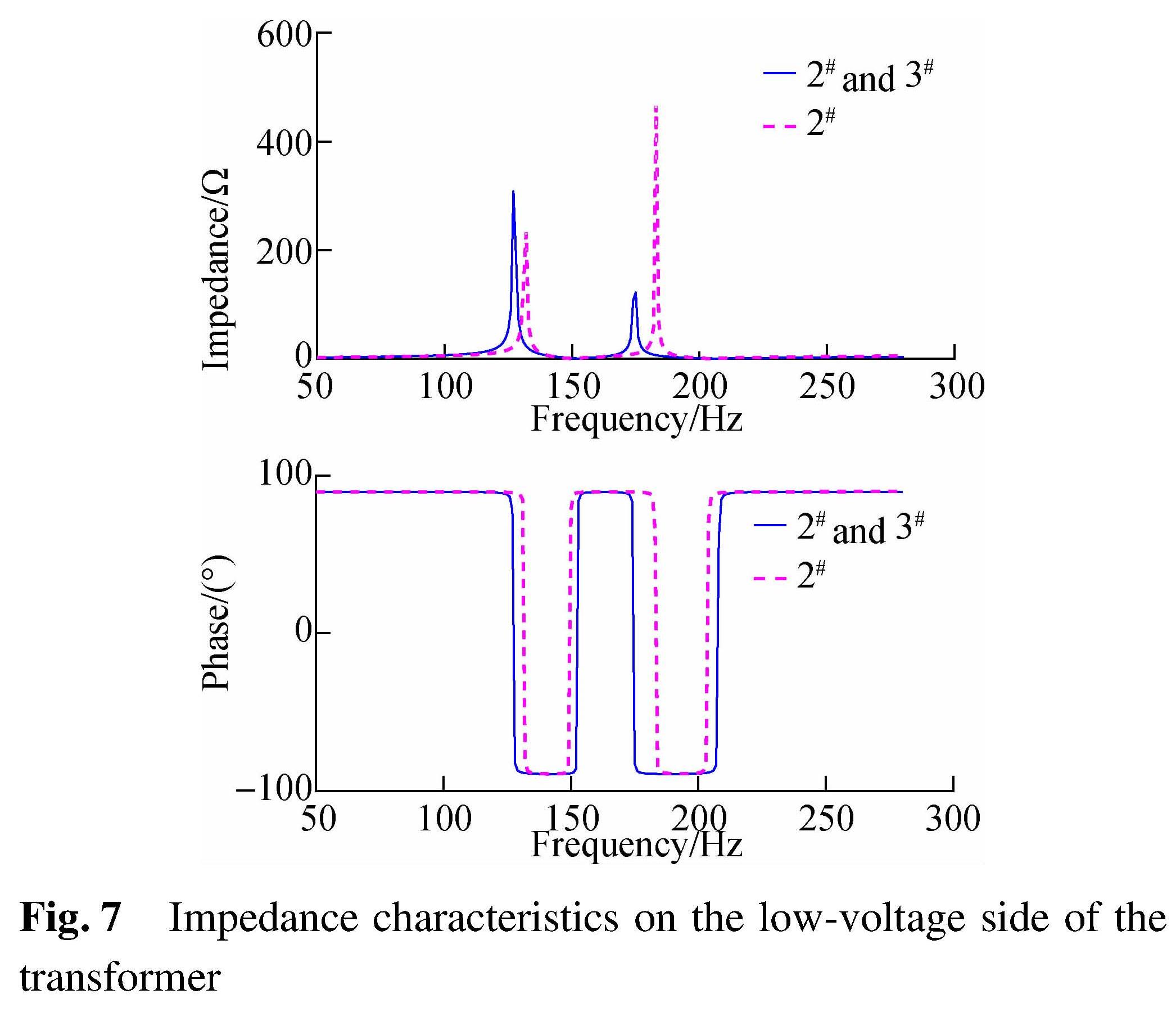
Fig.7 Impedance characteristics on the low-voltage side of the transformer
2.2 Magnetic coupling model of the transformer under magnetic biasing
Self-coupling transformer ODFPS-500000/750 adopts a single-phase four-column structure. Both main columns are equipped with low-medium-high voltage windings. The excitation current on each column is i0/2. By ignoring the influence of low-voltage windings under no-load conditions, the equivalent circuit model of each column is shown in Fig.8. The key parameters are shown in Tab.2.
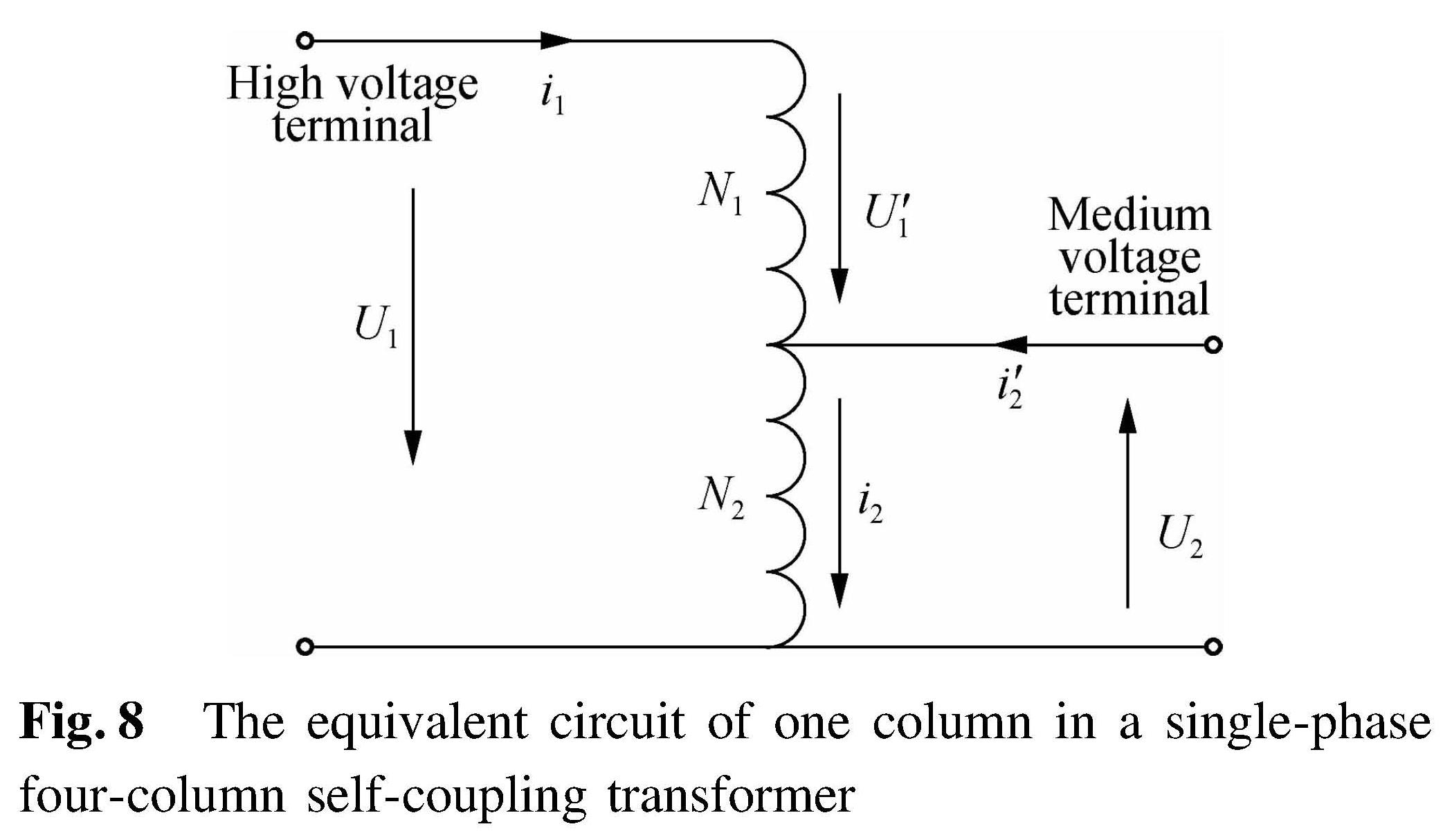
Fig.8 The equivalent circuit of one column in a single-phase four-column self-coupling transformer
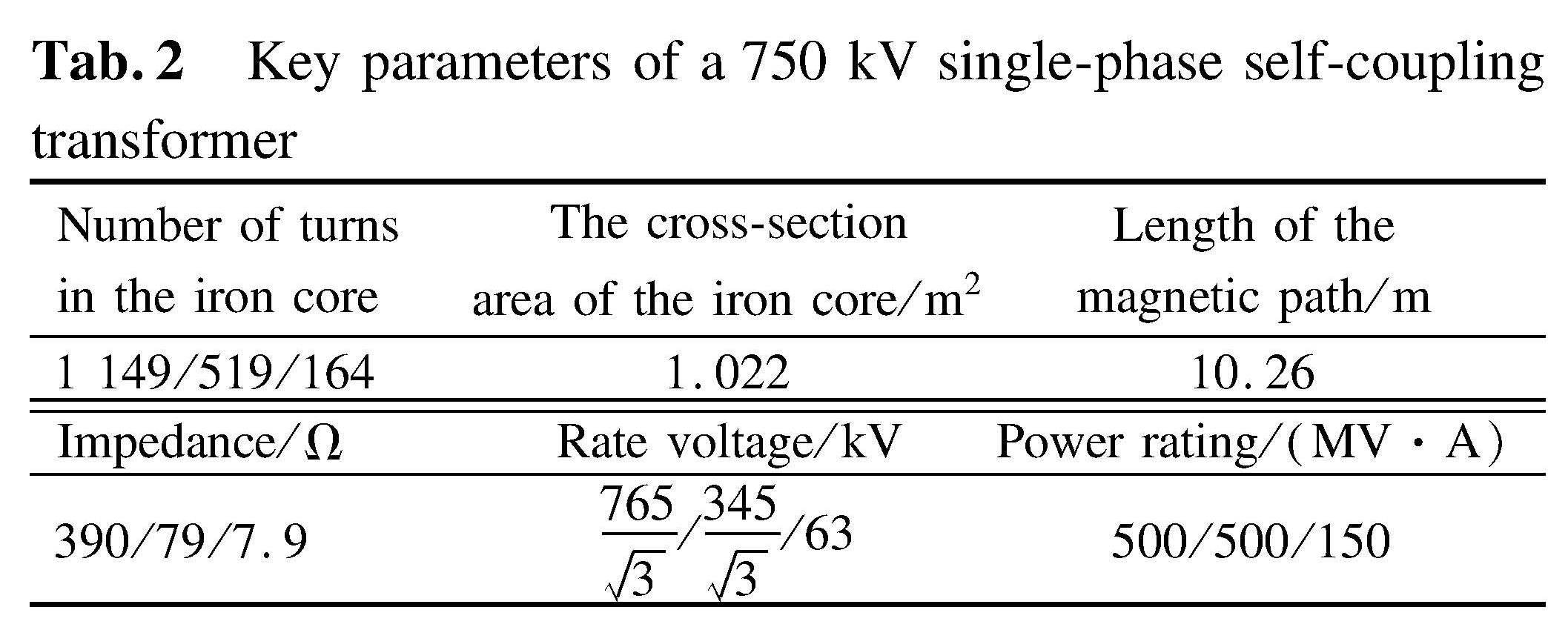
Tab.2 Key parameters of a 750 kV single-phase self-coupling transformer
The mathematical model of the single-phase self-coupling transformer is
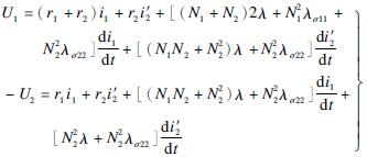 (8)
(8)
where U'1+(-U2)=U1U'1+(-U2)=U1; i1+i2=i2i1+i'2=i2; λσ11, λσ22 are the leakage permeances of each winding; N1 and N2 are the number of turns in each winding; λ is the main permeance. According to the classic Jiles-Atherton hysteresis model [16], we have
 (9)
(9)
where H is the magnetic field strength; M is the magnetization intensity; Man is the anhysteretic magnetization intensity of the typical magnetic material, and it is calculated as
Man=Ms(coth((H+αM)/(a))-(a)/(H+αM))(10)
δ=sgn(dH/dt)is the directional coefficient; Ms, a, α, c represent the characteristics of the iron core material, which are defined in Ref.[17]; km=k(1-0.96(M/Ms)2)is the dynamic modification value of k in Ref.[18]. The instant main permeance of the iron core can be calculated by λ=SμFe/lλ=SμFe/l, while μFe=μ0(1+dM/dH)μFe=μ0(1+dM/dH)is the permeability of the iron core, S is the cross-section area of the iron core and l is the length of the equivalent magnetic path.
By programming Eqs.(9)and(10)into the S-function blocks of Simulink software, the magnetic coupling model of the transformer is shown in Fig.9. The parameters of the highly-conductive cold-rolled silicon-steel sheet 57ZH100 used in the ODFPS-500000/750 transformer is obtained from Ref.[19](Ms=1.68 MA/m,k=10.918 9,c=0.3,α=13.9×10-6,a=8). Through simulations, the B-H curve and i0-μFe curves of the transformer's iron core under the no-load condition are shown in Fig.10.
The rated flux density B and peak value of magnetic field strength H are 1.67 T and 39.58 A/m, respectively. According to the no-load current ratio(0.05%), the rated excitation current of the transformer is 0.7 A. Compared with Fig.10, the B-H curve and the peak value of
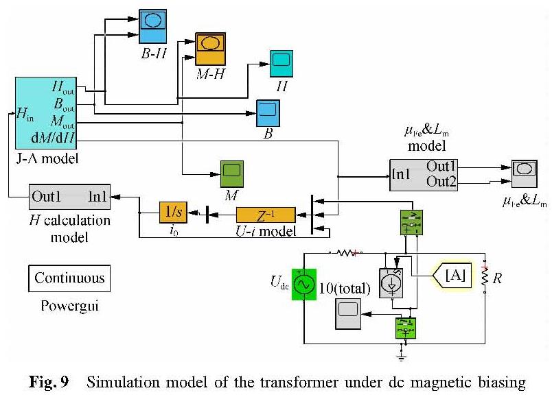
Fig.9 Simulation model of the transformer under dc magnetic biasing
the excitation current calculated from the simulation B-H curve matches the results on the manuscript of the transformer. The relative error of the rated excitation current is only 7.86%(The rated excitation current of the transformer is 0.645A on the manuscript). The reactive power loss of the transformer can be calculated as[20]
ΔQ=IbU1(11)
where Ib is the RMS value of the fundamental positive sequence component in the reactive component of the excitation current. Throughout the model simulation and Fourier analysis, it is set to be 0.278 5 A. Therefore, the no-load loss of the transformer is calculated as 0.120 6 Mvar, only 0.5% difference from the 120 kW no-load experimental result. These comparisons show that the simulation model is accurate.In the worst-case scenario(i.e. when the maximum magnetic biasing current is 145.95 A), the single-phase self-coupling reactive power loss Qdc is shown in Tab.3.
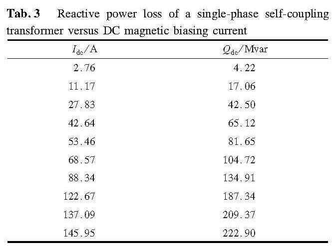
Tab.3 Reactive power loss of a single-phase self-coupling transformer versus DC magnetic biasing current
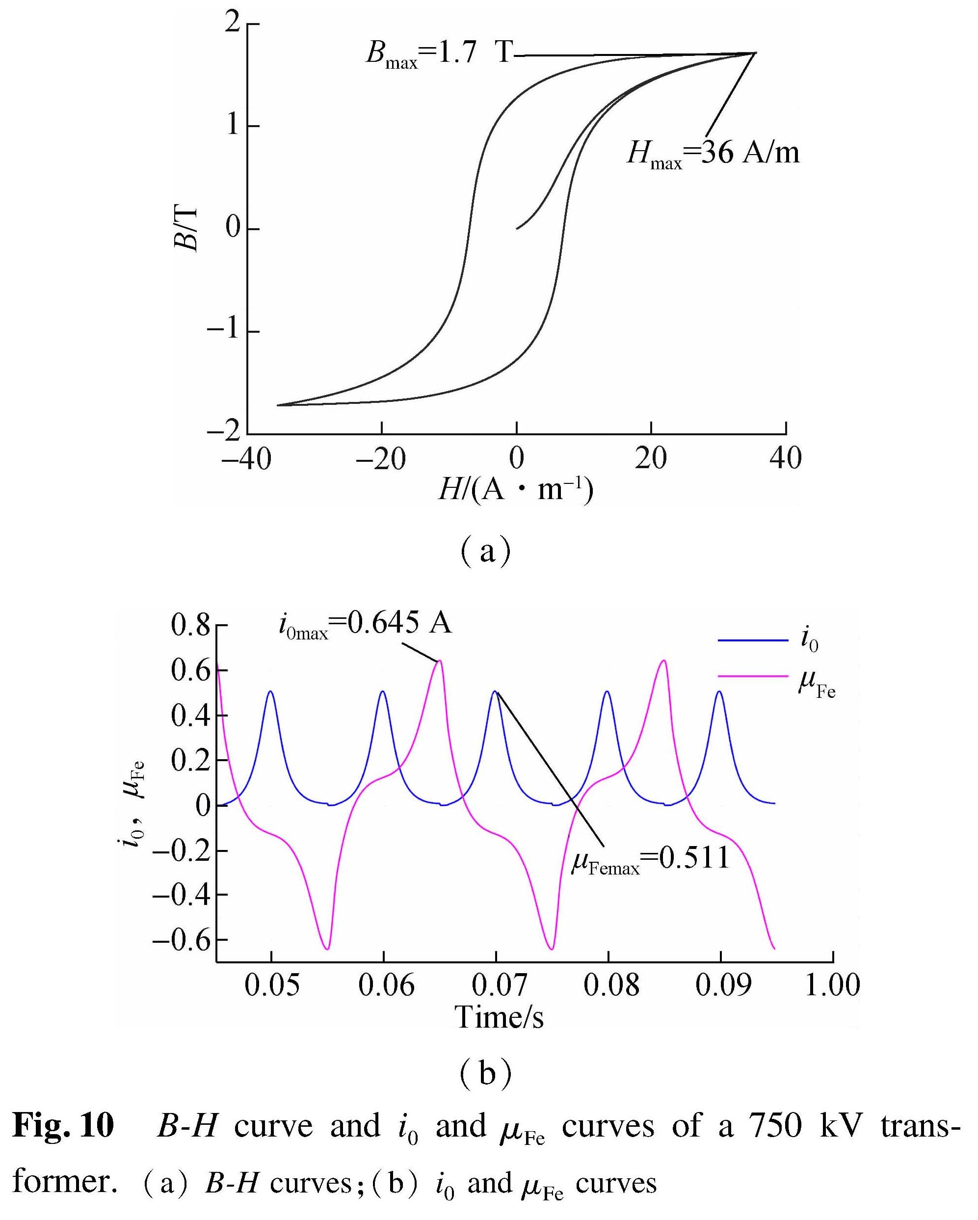
Fig.10 B-H curve and i0 and μFe curves of a 750 kV transformer.(a)B-H curves;(b)i0 and μFe curves
When Idc=122.67 A, Qdc reaches the maximum capacity of SVC, and Xt is reduced to 61.48% of the rated value. If Idc is further increased to 145.95 A, Xt will decrease to 57.29%. By the data fitting of Idc, Xt and Qdc, the approximate relationship is expressed as
Xt≈-0.00 2806 Idc+0.952 5≈-0.001 837 Qdc+0.952 5(12)
Following the analysis above,the relationships among the equivalent impedance of transformer Xt, magnetic current and reactive power loss are simulated to be linear as shown in Fig.11. Therefore, Xt is used to evaluate the magnetic biasing condition in this paper instead of Idc and Qdc.

Fig.11 Relationships among the equivalent impedance of transformer Xt, magnetic current and reactive power loss
3 Simulation of a 750 kV UHVT with Parallel SVC under Magnetic Bias3.1 The impedance/frequency characteristics of a UHVT with parallel SVC system
The 750 kV three-phase UHVT-PSVC(type TCR+FC)described in Section 2 is applied in this simulation. When the series-reactance rate is increased to 12%,6% and 6%, the effect of the dc magnetic biasing on the input impedance on the low-voltage side of the transformer is simulated in this section.
1)Method 1. While TCR is switched off, the frequency/impedance characteristics on the low-voltage side of the transformer are analyzed in Tab.4. Four classic data sets are categorized into 2 groups(with different FC branches turned on)and simulated correspondingly. The value and angle of input impedances on the low-voltage side of the transformer under different magnetic biasing currents are shown in Figs.12 to 14.
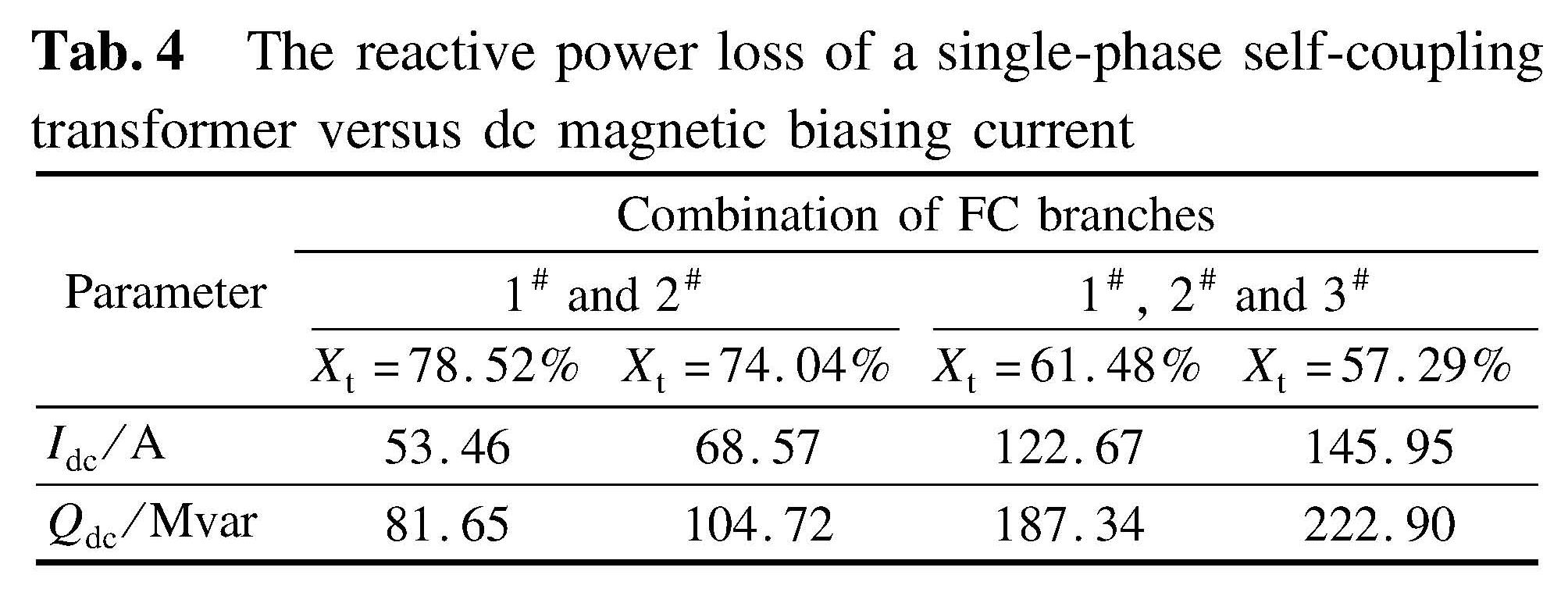
Tab.4 The reactive power loss of a single-phase self-coupling transformer versus dc magnetic biasing current
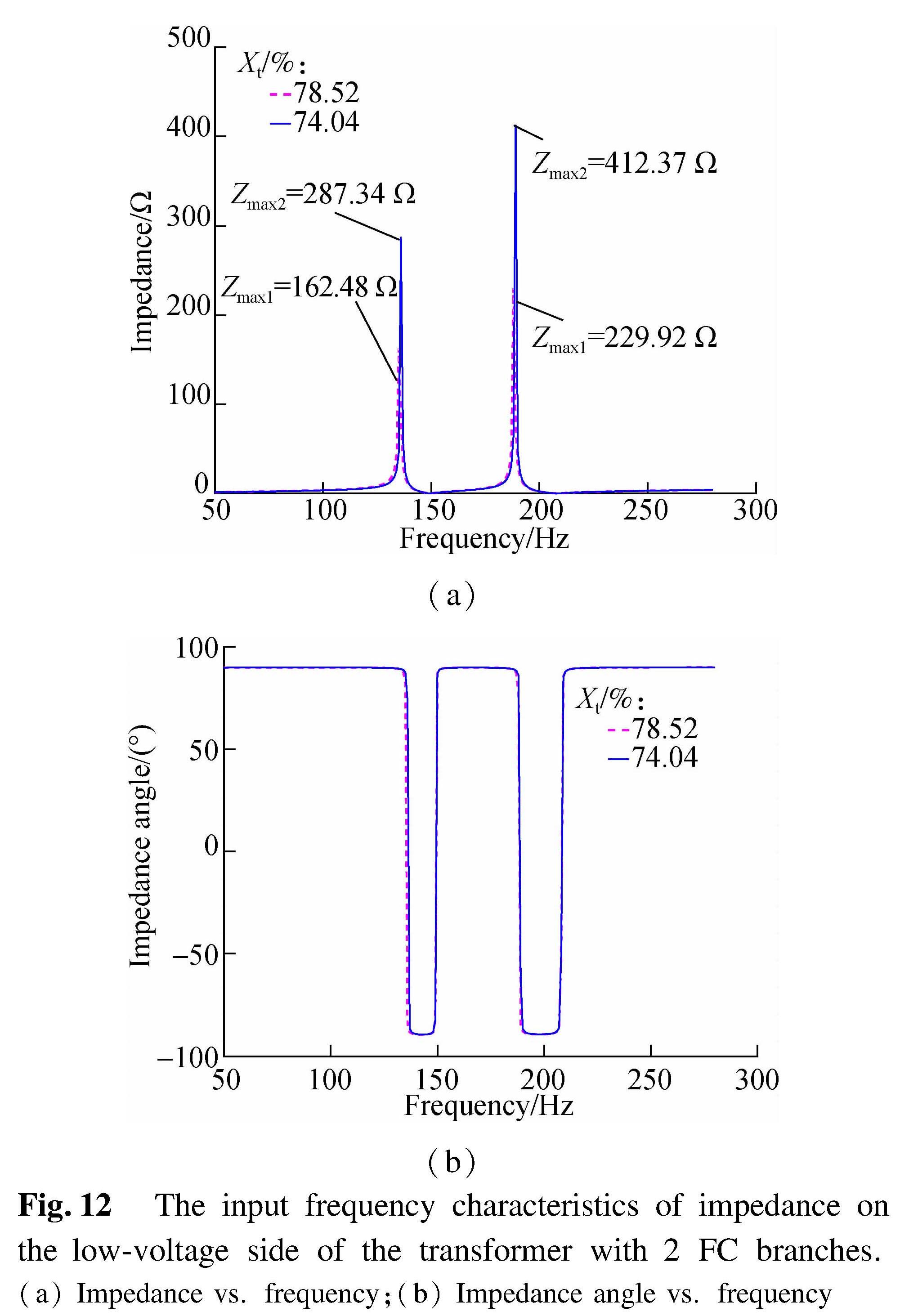
Fig.12 The input frequency characteristics of impedance on the low-voltage side of the transformer with 2 FC branches.(a)Impedance vs. frequency;(b)Impedance angle vs. frequency

Fig.13 Impedance/frequency characteristics on the low voltage side of the transformer with 3 FC branches.(a)Impedance vs. frequency;(b)Impedance angle vs. frequency
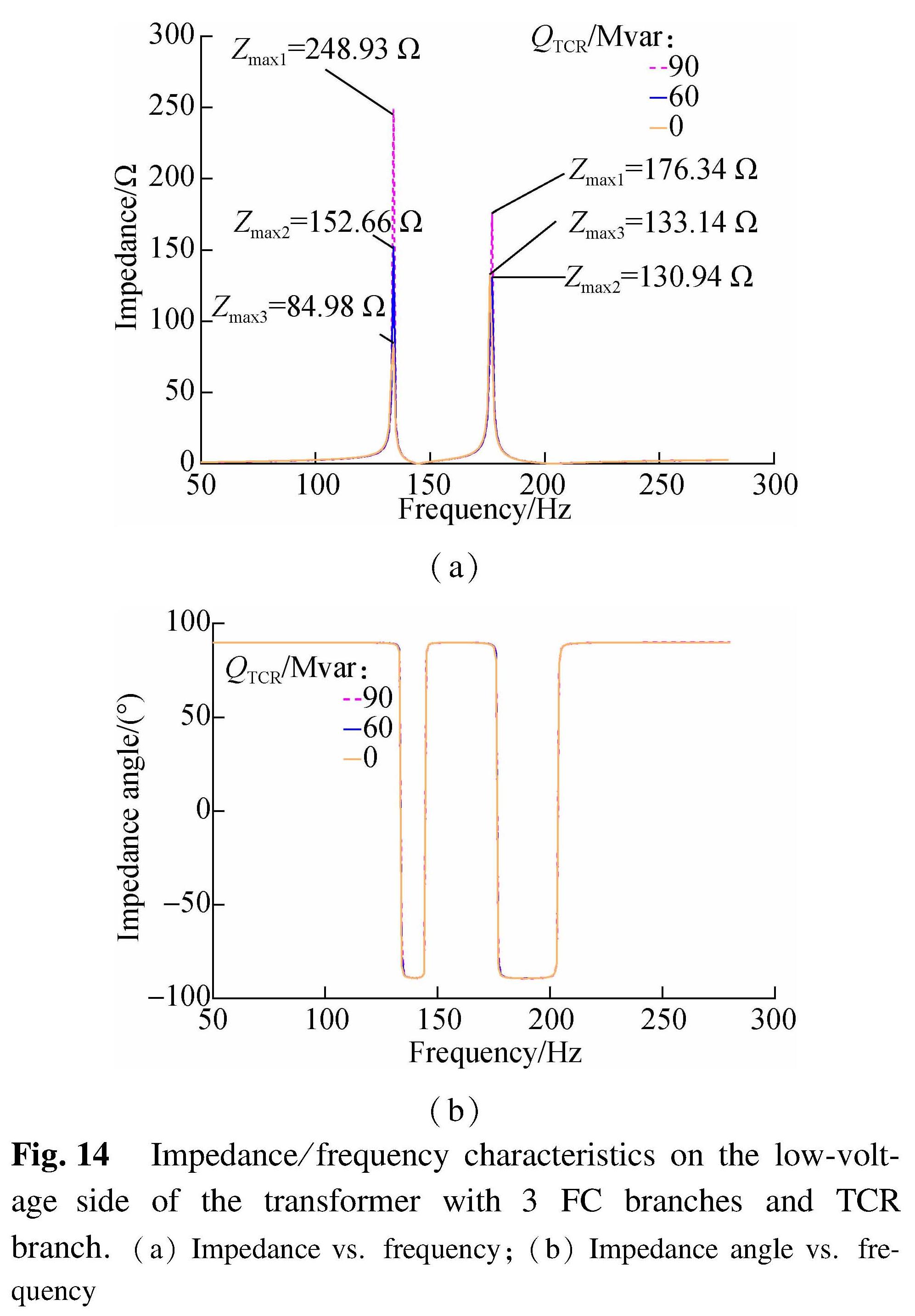
Fig.14 Impedance/frequency characteristics on the low-voltage side of the transformer with 3 FC branches and TCR branch.(a)Impedance vs. frequency;(b)Impedance angle vs. frequency
With the increase in magnetic biasing current and the activation of 2 FC branches, the 2nd resonance point occurs around 185 Hz. The impedance under the 4th harmonic condition is proved to be capacitive. With the decrease in the transformer's equivalent impedance, both the frequency and amplitude of the parallel system resonance point change drastically. When Xt=74.84%, the peak value of impedance in 187 Hz is 1.79 times that of 78.52%.
With the further increase in magnetic biasing current, the equivalent impedance of the transformer keeps decreasing. The third FC branch is switched on to compensate for the reactive power loss caused by magnetic biasing. The input impedance value and the impedance angle with 3 FC branches are shown in Fig.13.
By comparing Fig.12 with Fig.13, it is observed that the 2nd parallel resonance point with 2 FC branches is closer to the 4th harmonic. With the connection of the 3rd FC branch, the saturation level of the iron core in the transformer keeps rising, which causes the system parallel resonance points to fluctuate between the 3rd and 4th harmonics. The peak impedance value of the resonance point is decreased as well as the capacitive area of the impedance angle. When Xt=57.29%, the system parallel resonance points are located between 134 and 177 Hz. The 4th harmonic impedance value is increased.
2)Method 2. The simulation result of Method 2 is analyzed in Fig.13. In this simulation, 3 FC branches are switched on while the equivalent impedance of the transformer is set to be 57.29%. When TCR branches are switched on and provide 60/90 Mvar reactive power for the system, the total power provided by the SVC is 120 and 90 Mvar. The impedance/frequency characteristics under these 2 situations are simulated as shown in Fig.14.
When 90 Mvar inductive power is provided by SVC, the 2nd parallel resonance point is 1 Hz away from the previous resonance point. The input impedance value on the parallel resonance point between 135 and 178 Hz is significantly increased. However, if the TCR inductive power is limited to 60 Mvar, the change of impedance value on 177 Hz resonance point will not be large. Therefore, the harmonic content generated by the TCR branch can be controlled properly.
Theoretically, the maximum 3-phase dc magnetic biasing current caused by the magnetic storm on a 750 kV system is 200 A. For each phase, the current is 66.7 A. The 4th harmonic parallel resonance between Zsys and ZSVC is most likely to occur when two FC branches are switched on for compensating Qdc caused by 53 to 68 A dc magnetic biasing current. This should be avoided.
3.2 Effect of the proposed resonance control procedureAs the operating voltage on the low-voltage side of the transformer is 1.05 times the normal voltage(Ur=1.05 UN), the parameters of FC branches in each SVC device are reconfigured as shown in Tab.5. In this configuration, the by-pass switch is only installed on the 7th FC branch. During normal operation, the inductance stays at 10.03 mH. Under magnetic biasing conditions, the switch is cut-off and increases the inductance into 17.08 mH. The structure of the whole UHVT-PSVC after modification is shown in Fig.15.
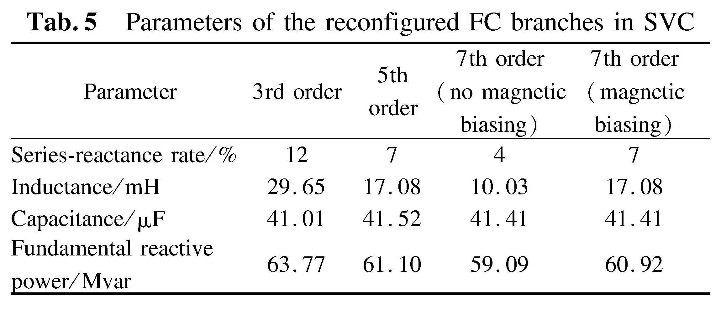
Tab.5 Parameters of the reconfigured FC branches in SVC
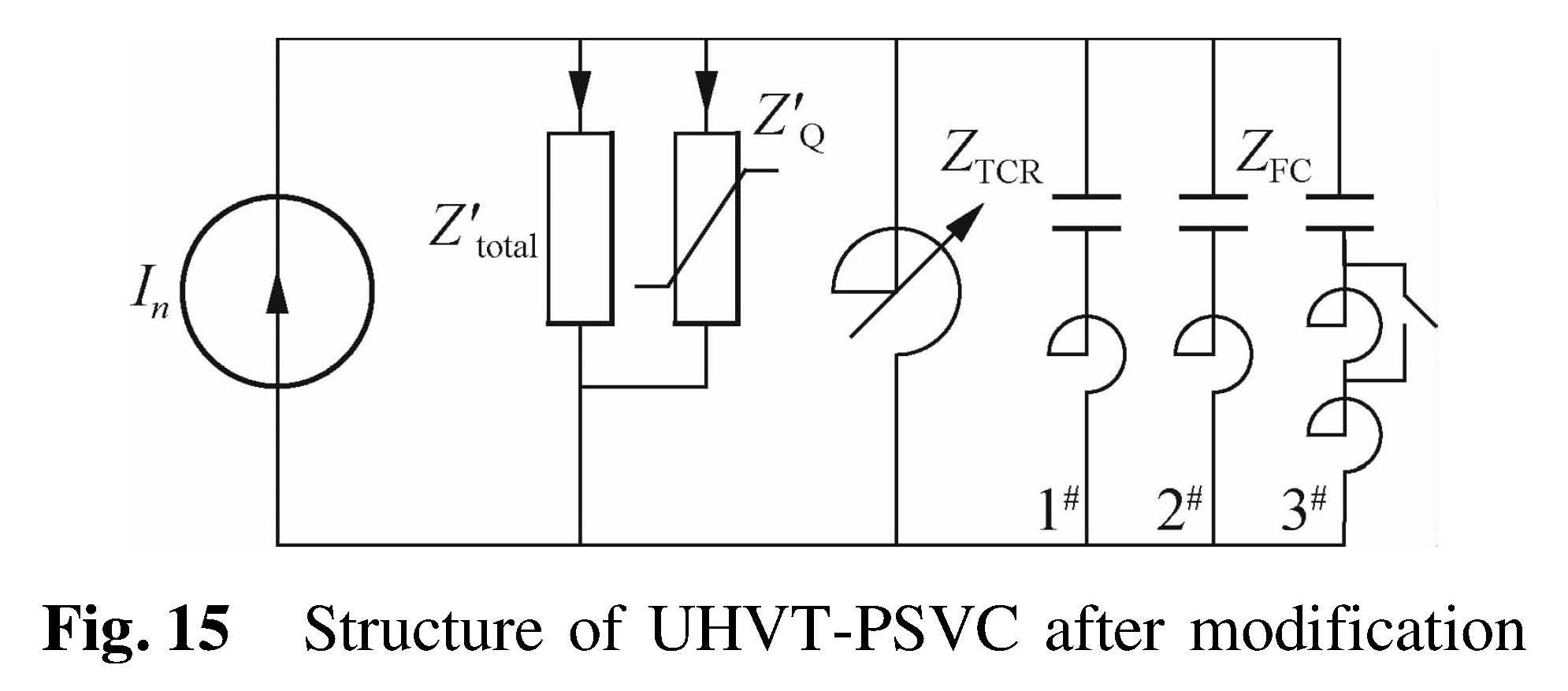
Fig.15 Structure of UHVT-PSVC after modification
During normal operation, the impedance on the low-voltage side of the transformer and all branches in SVC are shown in Figs.16 and 17 when K is set to be 12%, 7% and 4%. It is confirmed that the SVC device after reconfiguration can reduce the 3rd,5th and 7th harmonics significantly. All branch impedances above the 3rd harmonic can remain inductive.

Fig.16 Impedance/frequency characteristics on the low-voltage side of the transformer with 3 FC branches(no magnetic biasing)
If no magnetic biasing is detected, and switch K in the 7th order FC branch is accidentally turned off, in this case, the 7th harmonic series-reactance rate will increase to 7%. The impedance characteristics on the low-voltage side of the transformer with different branches are shown in Fig.18.
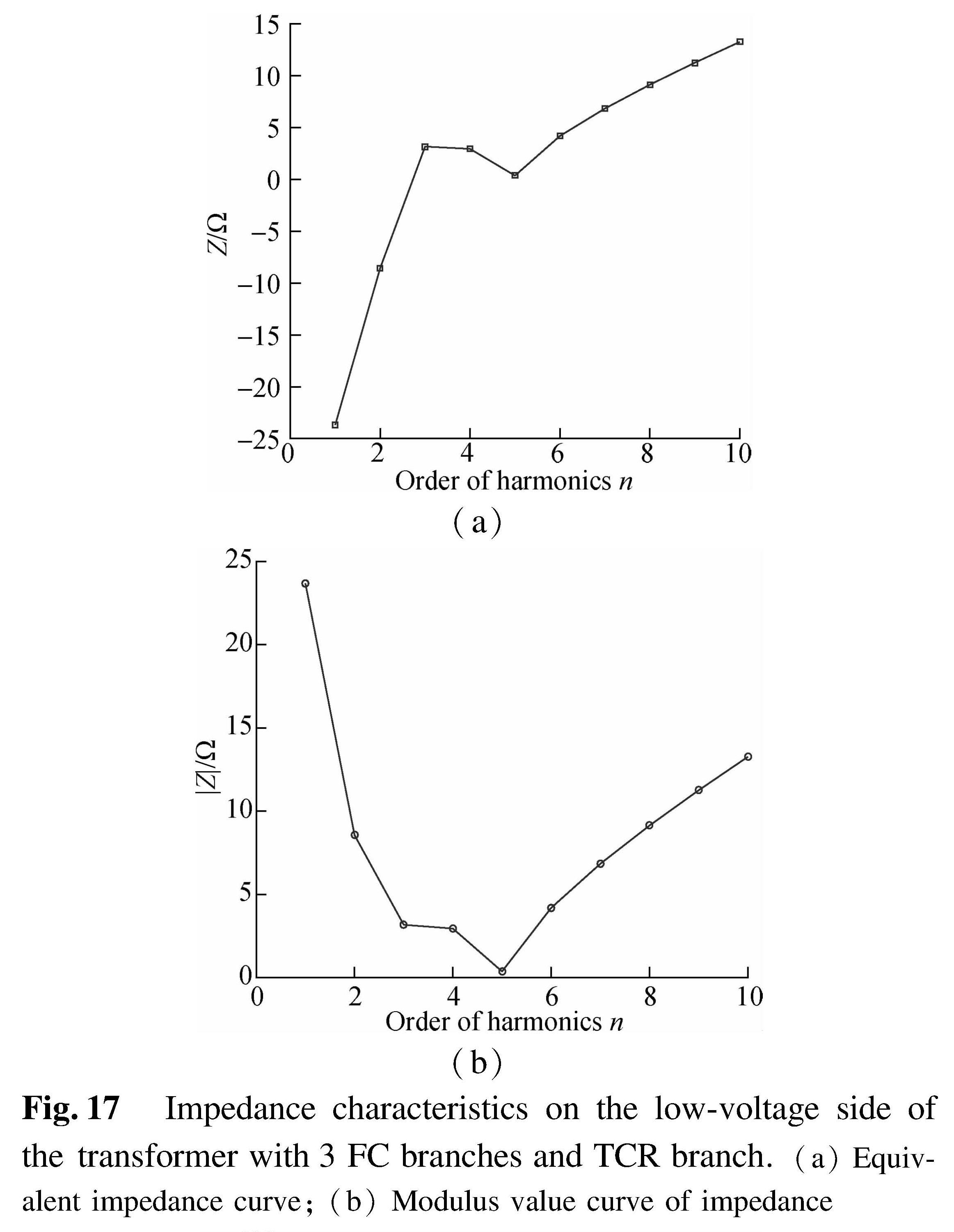
Fig.17 Impedance characteristics on the low-voltage side of the transformer with 3 FC branches and TCR branch.(a)Equivalent impedance curve;(b)Modulus value curve of impedance
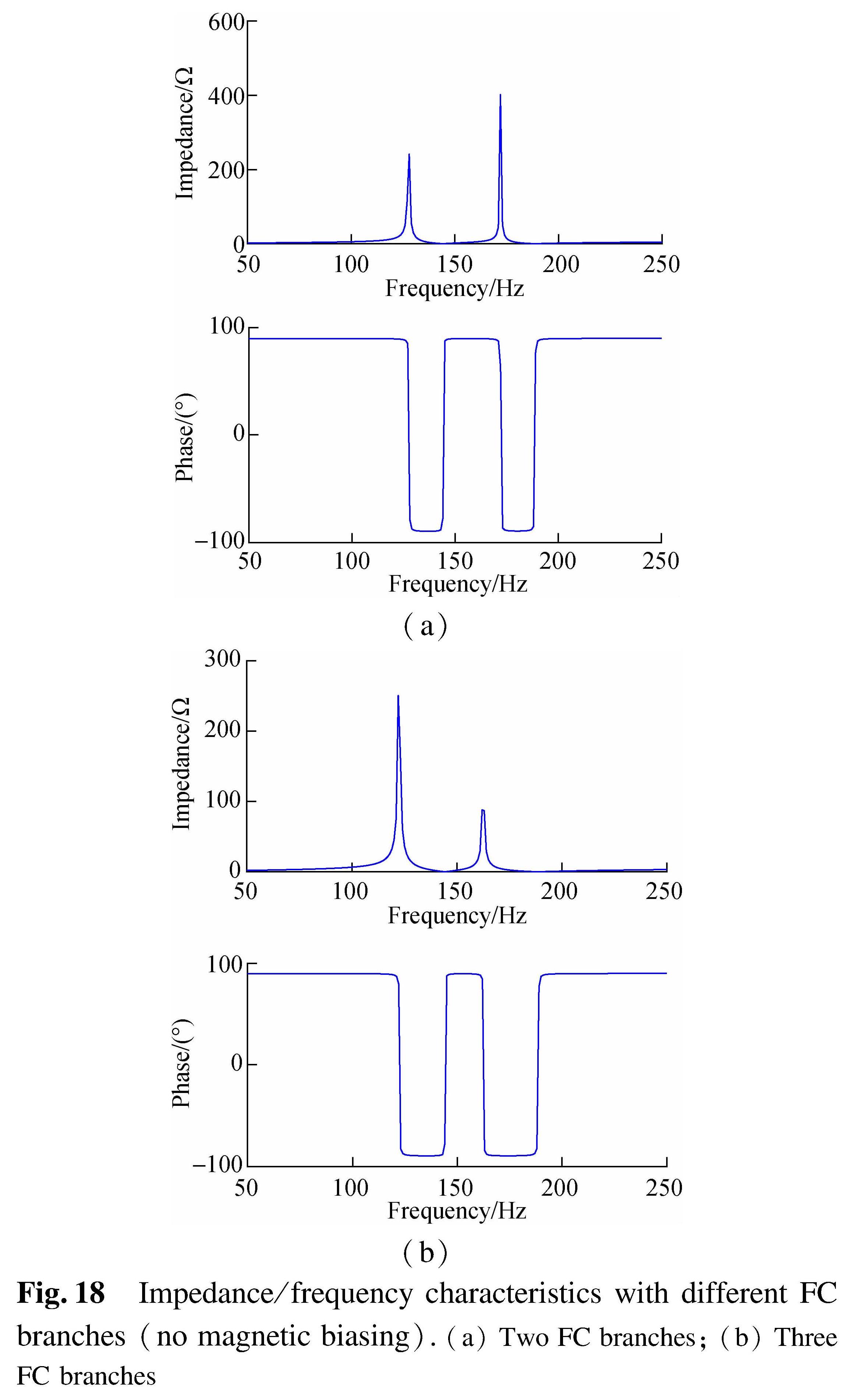
Fig.18 Impedance/frequency characteristics with different FC branches(no magnetic biasing).(a)Two FC branches;(b)Three FC branches
Comparing Fig.16 with Fig.18, it is fair to say that the SVC with a new configuration can properly set the system parallel resonance point away from the 2nd,3rd and 4th harmonics during normal operation. No negative influence can be found in this process.
If magnetic biasing is detected, the bypass switch is turned off, which increases the K value of FC branches to 12%,7% and 7%. The changes of input impedance characteristics on the low-voltage side of the transformer with the decrease in Xt(i.e. increasing of magnetic biasing condition)are shown in Figs.19 and 20.
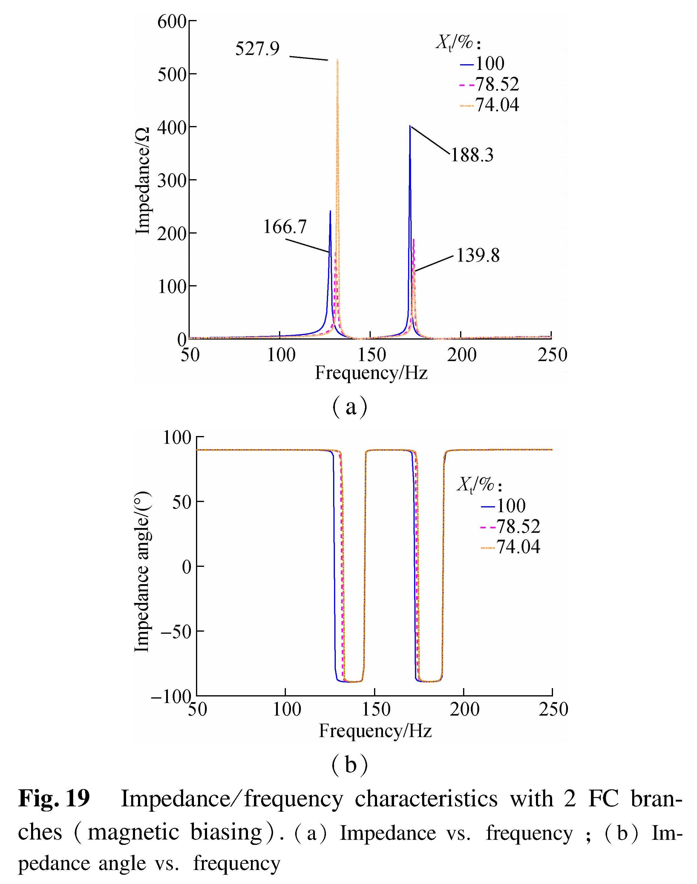
Fig.19 Impedance/frequency characteristics with 2 FC branches(magnetic biasing).(a)Impedance vs. frequency;(b)Impedance angle vs. frequency
Apparently, by adjusting the K value of FC branches, two parallel resonance points of the input impedance on the low-voltage side can be controlled far away from the 3rd and 4th harmonics. Even with strong magnetic biasing(Xt drops to only 57.29%), the 4th harmonic impedance of the system can still be kept inductive, preventing the corresponding parallel resonance. The impedance changes of SVC devices with different FC branches are shown in Fig.21.
It is proved that the 4th harmonic impedance of the SVC can be kept inductive for all the switching patterns. Harmonic amplification can also be prevented.
To conclude, the proposed resonance fault control device and its corresponding resonance control method can prevent the system from parallel resonance or harmonic amplification under different magnetic biasing without influencing the normal compensation of SVC. It can also reduce harmonic efficiently during normal operation. The fault control method is proved to be valid and can improve system stability.
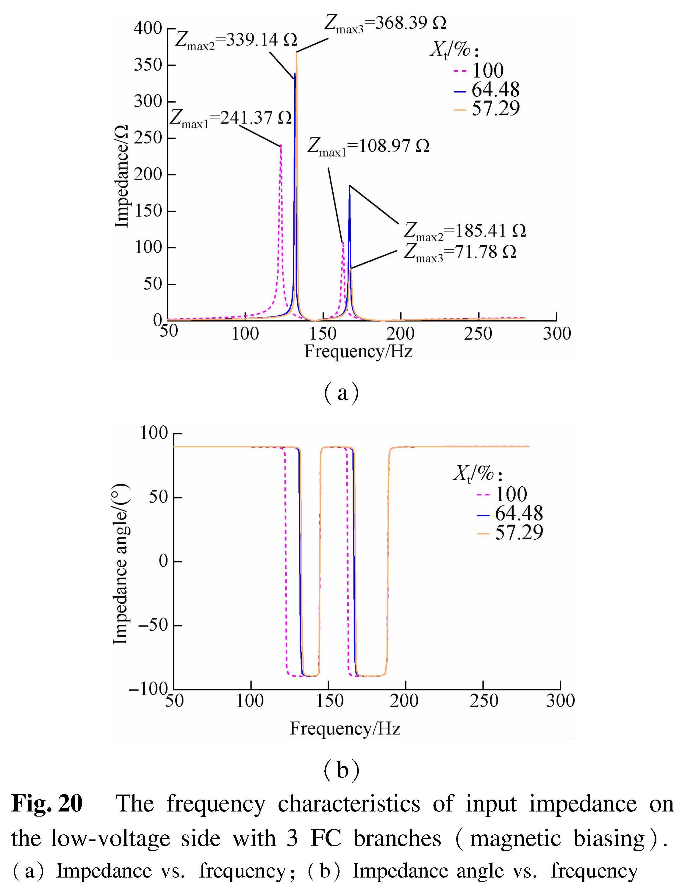
Fig.20 The frequency characteristics of input impedance on the low-voltage side with 3 FC branches(magnetic biasing).(a)Impedance vs. frequency;(b)Impedance angle vs. frequency

Fig.21 Branch impedance characteristic on the low-voltage side of the transformer with different numbers of FC branches.(a)Equivalent impedance;(b)The absolute value of the impedance
4 Conclusions
1)Under magnetic biasing, if the series-reactance rates of 3 FC branches in SVC are lower than 12%,6% and 6%, the 4th harmonic resonance and harmonic amplification will occur on the low-voltage side of the transformer.Although the reactive power loss of the transformer may be compensated by SVC, the potential resonance fault should still be avoided due to the potential harmonic amplification.
2)By using the proposed resonance control method, the series-reactance rates of all branches are adjusted to 12%, 7% and 4%/7%(without/with magnetic biasing). Combined with the restriction of TCR capacity, it can eliminate the 4th harmonic resonance and amplification under magnetic biasing.
3)The magnetic-field coupling model of the transformer based on J-A hysteresis can simulate the dynamic parameter and reactive power loss under various conditions. With the assistance of the impedance/frequency analysis model of UHVT-PSVC, the connections between the magnetic biasing current and equivalent impedance can be analyzed properly under various conditions. This provides a valid solution for the simulation of the impedance/frequency characteristics for different equipment under different magnetic biasing.
- [1] Liu L G, Qian C, Zhu X, et al. Calculation of geomagnetically induced currents reactive power loss disturbance in Gansu Grid with parameter K [J]. Power System Technology, 2016, 40(8):2370–2375. DOI:10.13335/j.1000-3673.pst.2016.08.018.(in Chinese)
- [2] Rezaei-Zare A. Reactive power loss versus GIC characteristic of single-phase transformers[J].IEEE Transactions on Power Delivery, 2015, 30(3): 1639-1640. DOI:10.1109/TPWRD.2015.2394311.
- [3] Zhang S M, Liu L G. Research on the GIC governance scheme of the Xinjiang 750-kV power grid based on an equal allocation method[J].IEEE Access, 2020, 8: 75419-75427. DOI:10.1109/access.2020.2989167.
- [4] Annakkage U D, McLaren P G, Dirks E, et al. A current transformer model based on the Jiles-Atherton theory of ferromagnetic hysteresis[J].IEEE Transactions on Power Delivery, 2000, 15(1): 57-61. DOI:10.1109/61.847229.
- [5] Overbye T J, Hutchins T R, Shetye K, et al. Integration of geomagnetic disturbance modeling into the power flow: A methodology for large-scale system studies[C]//2012 North American Power Symposium. Champaign, IL, USA, 2012: 1-7. DOI:10.1109/NAPS.2012.6336365.
- [6] Boteler D H, Bradley E. On the interaction of power transformers and geomagnetically induced currents[J].IEEE Transactions on Power Delivery, 2016, 31(5): 2188-2195. DOI:10.1109/TPWRD.2016.2576400.
- [7] Li B, Wang Z Z, Liu K, et al. Research on winding current of UHV transformer under DC-bias [J].Transactions of China Electrotechnical Society, 2020, 35(7):1422-1431.DOI:10.19595/j.cnki.1000-6753.tces.190293.(in Chinese)
- [8] Chen D Z, Feng Z Y, Wang Q P, et al. Study of analysis and experiment for ability to withstand DC bias in power transformers[J].IEEE Transactions on Magnetics, 2018, 54(11): 1-6. DOI:10.1109/TMAG.2018.2844208.
- [9] Chen Z W, Li H M, Liu L W, et al. DC bias treatment of hybrid type transformer based on magnetic flux modulation mechanism[J].IEEE Transactions on Magnetics, 2019, 55(6): 1-4. DOI:10.1109/TMAG.2019.2903566.
- [10] Yao Y Y. Research on the DC bias phenomena of large power transformers [D].Shenyang: Shenyang University of Technology, 2000.
- [11] Zhang S M, Liu L G. A mitigation method based on the principle of GIC-even distribution in whole power grids[J].IEEE Access, 2020, 8: 65096-65103. DOI:10.1109/access.2020.2984262.
- [12] Yang Y F, Xu B Y, Mei G H, et al.Selection of series reactance ratio of substation capacitor banks in AC/DC hybrid power grid [J]Electric Power Automation Equipment, 2009, 29(6):29-34.(in Chinese)
- [13] Liu L G, Chen Q, Qin X P. Calculation of geomagnetically induced currents reactive power loss disturbance in China's UHV power grid considering the influence of 500 kV power grid[J].Scientia Sinica(Technological), 2016, 46(11):1146-1156.(in Chinese)
- [14] Liu L G, Wu W L. Security risk assessment ideas and theoretical framework for power system considering geomagnetic storm [J].Proceedings of the CSEE, 2014, 34(10):1583-1591.DOI:10.13334/j.0258-8013.pcsee.2014.10.009(in Chinese)
- [15] Liu T T, Liu L G. Analysis of impact of transformer DC bias harmonic on shunt capacitors [J].Modern Electric Power, 2012, 29(1):29-32.DOI:10.19725/j.cnki.1007-2322.2012.01.007.(in Chinese)
- [16] Zhang B. Study on GIC effect of large power transformers [D].Beijing: North China Electric Power University, 2010.(in Chinese)
- [17] Li Z, Li Q M, Li C Y, et al. Queries on the J-A modeling theory of the magnetization process in ferromagnets and proposed correction method [J].Proceedings of the CSEE, 2011, 31(3):124-131.DOI:10.13334/j.0258-8013.pcsee.2011.03.001(in Chinese)
- [18] Li Z. Study on magnetization mechanism and modelling methodology of power transformer under DC bias [D]. Jinan: Shandong University, 2011.
- [19] Emanuel A E. Powers in nonsinusoidal situations—a review of definitions and physical meaning[J].IEEE Transactions on Power Delivery, 1990, 5(3): 1377-1389. DOI:10.1109/61.57980.